1
/
of
10
PayPal, credit cards. Download editable-PDF and invoice in 1 second!
SN/T 3077.1-2012 English PDF (SNT3077.1-2012)
SN/T 3077.1-2012 English PDF (SNT3077.1-2012)
Regular price
$175.00 USD
Regular price
Sale price
$175.00 USD
Unit price
/
per
Shipping calculated at checkout.
Couldn't load pickup availability
Delivery: 3 seconds. Download true-PDF + Invoice.
Get Quotation: Click SN/T 3077.1-2012 (Self-service in 1-minute)
Historical versions (Master-website): SN/T 3077.1-2012
Preview True-PDF (Reload/Scroll-down if blank)
SN/T 3077.1-2012: Test method for flash point by continuously closed cup tester
SN/T 3077.1-2012
SN
ENTRY-EXIT INSPECTION AND QUARANTINE INDUSTRY
STANDARD OF THE PEOPLE’S REPUBLIC OF CHINA
Test method for flash point by continuously closed cup tester
ISSUED ON: MAY 07, 2012
IMPLEMENTED ON: NOVEMBER 16, 2012
Issued by: General Administration of Quality Supervision, Inspection and
Quarantine of PRC
Table of Contents
Foreword ... 3
1 Scope ... 4
2 Normative references ... 4
3 Terms and definitions ... 4
4 Method summary ... 5
5 Significance and use ... 5
6 Equipment ... 6
7 Reagents and materials ... 7
8 Sampling ... 8
9 Quality control ... 8
10 Preparation of instruments ... 9
11 Test procedure ... 9
12 Flash point correction ... 11
13 Report ... 11
14 Precision and deviation ... 12
Appendix A (Normative) Instrument specifications ... 13
Appendix B (Informative) Liquids used for instrument calibration ... 15
Test method for flash point by continuously closed cup tester
1 Scope
This Part of SN/T 3077 specifies the method for determining the flash point of
continuously closed cup.
This Part is applicable to the determination of the flash point of fuel oil, lubricating oil,
solvent oil and other liquids; its determination range is 10 °C ~ 250 °C.
Note: Flash points below 10 °C or above 250 °C can be measured, but the precision has not
been obtained.
If the user's product requires a specified flash point test method other than this method,
neither this method nor any other method can replace the specified method without
comparative data and the approval of the specification developer.
2 Normative references
The following documents are essential to the application of this document. For the dated
documents, only the versions with the dates indicated are applicable to this document;
for the undated documents, only the latest version (including all the amendments) is
applicable to this standard.
GB/T 4756 Petroleum liquids - Manual sampling (GB/T 4756-1998, eqv ISO
3170:1988)
3 Terms and definitions
The following terms and definitions apply to this document.
3.1
Flash point
The lowest temperature (corrected to 101.3 kPa pressure) at which the vapor of the
specimen ignites under the specified test conditions.
Note 1: For the substance being tested, the flash point is not a constant physical and
chemical property, but a collection of instrumentation, instrument use, test process.
Therefore, the flash point can only be defined according to the method. The results measured
by different methods or different test instruments do not have a universally valid correlation.
Note 2: When the pressure increase caused by the hot flame in the closed test chamber is at
least 20 kPa, it is confirmed that the specimen has flashed.
3.2
Dynamic
The state when the vapor on the specimen and the specimen have not reached
temperature equilibrium when the fire source is introduced.
4 Method summary
Adjust the temperature of the test chamber lid to be less than 18 °C below the expected
flash point. Inject 1 mL ± 0.1 mL of sample into the sample cup. The temperature of the
sample and the sample cup shall be less than 18 °C below the expected flash point; it
can be cooled if necessary. Lift the sample cup and press the lid of the specified size, to
form a continuously closed but unsealed test chamber, which has a total volume of 4.0
mL ± 0.2 mL.
Close the measuring chamber; the temperature difference between the specimen and
the lid shall be within 1 °C; the lid is heated at a specified constant rate. An arc of a
certain energy is discharged in the test chamber at a specified time interval. After each
ignition, 1.5 mL ± 0.5 mL of air is introduced into the test chamber to provide the
required oxygen for the next flash test. Except for the short time when air is introduced
and when the flash point is reached, the pressure in the continuously closed but not
sealed test chamber shall be the ambient atmospheric pressure.
After each arc discharge, the pressure increase in the test chamber is detected to be
higher than the atmospheric pressure. When the pressure increase exceeds the specified
critical value, the temperature is recorded as the uncorrected flash point.
5 Significance and use
Flash point is a measure of the tendency of the specimen to form a flammable mixture
with air under specified test conditions. It is only one of the indicators for evaluating
all combustion hazards of a substance.
This test method is used to measure and describe the sensitivity of a substance to heat
and ignition sources under controlled test conditions; it cannot be used to describe and
evaluate the fire risk of a substance under actual ignition conditions.
Flash point can be used to indicate that highly volatile or flammable substances may
exist in relatively non-volatile or non-flammable substances, such as lubricating oil
containing a small amount of diesel or gasoline.
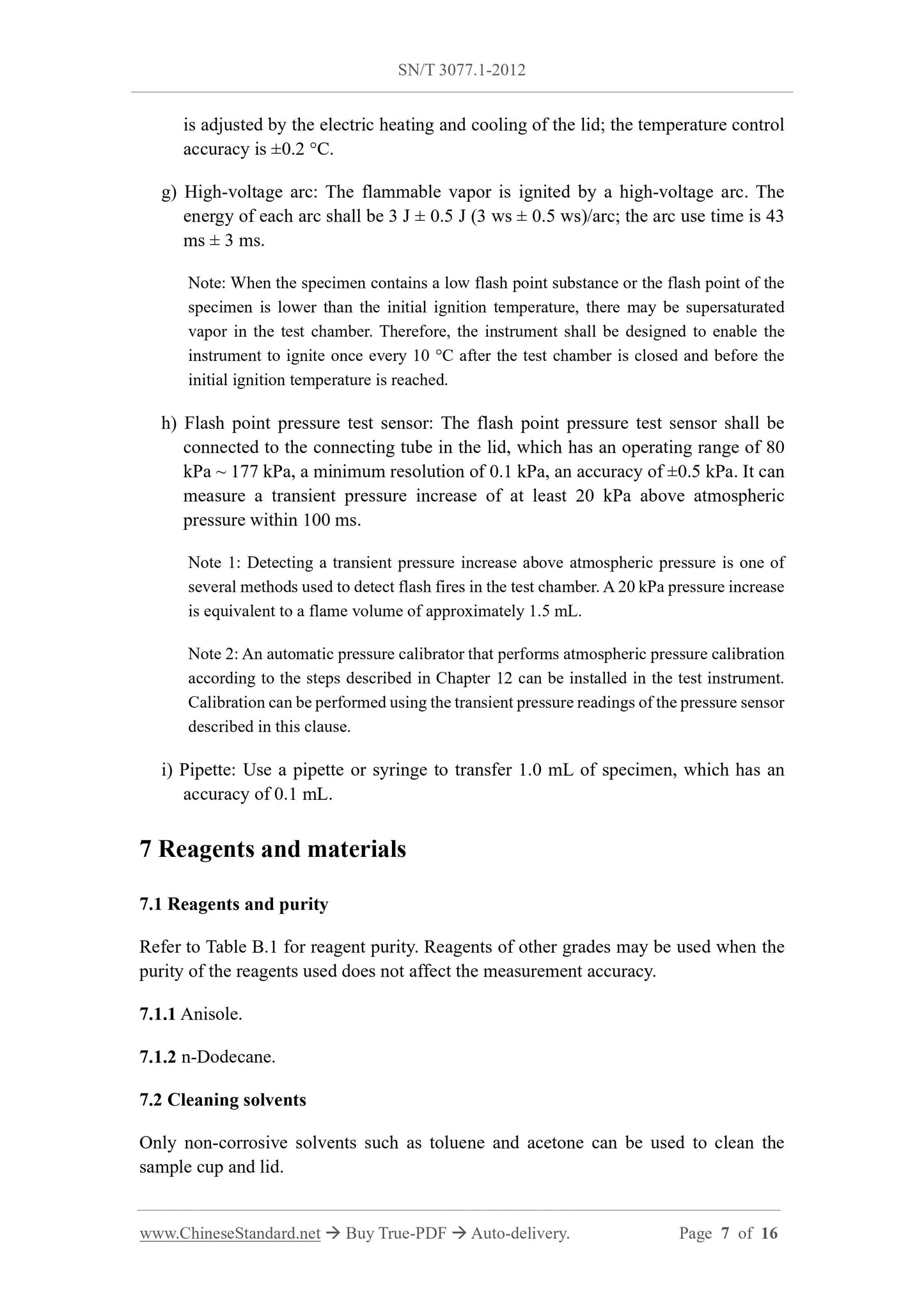
is adjusted by the electric heating and cooling of the lid; the temperature control
accuracy is ±0.2 °C.
g) High-voltage arc: The flammable vapor is ignited by a high-voltage arc. The
energy of each arc shall be 3 J ± 0.5 J (3 ws ± 0.5 ws)/arc; the arc use time is 43
ms ± 3 ms.
Note: When the specimen contains a low flash point substance or the flash point of the
specimen is lower than the initial ignition temperature, there may be supersaturated
vapor in the test chamber. Therefore, the instrument shall be designed to enable the
instrument to ignite once every 10 °C after the test chamber is closed and before the
initial ignition temperature is reached.
h) Flash point pressure test sensor: The flash point pressure test sensor shall be
connected to the connecting tube in the lid, which has an operating range of 80
kPa ~ 177 kPa, a minimum resolution of 0.1 kPa, an accuracy of ±0.5 kPa. It can
measure a transient pressure increase of at least 20 kPa above atmospheric
pressure within 100 ms.
Note 1: Detecting a transient pressure increase above atmospheric pressure is one of
several methods used to detect flash fires in the test chamber. A 20 kPa pressure increase
is equivalent to a flame volume of approximately 1.5 mL.
Note 2: An automatic pressure calibrator that performs atmospheric pressure calibration
according to the steps described in Chapter 12 can be installed in the test instrument.
Calibration can be performed using the transient pressure readings of the pressure sensor
described in this clause.
i) Pipette: Use a pipette or syringe to transfer 1.0 mL of specimen, which has an
accuracy of 0.1 mL.
7 Reagents and materials
7.1 Reagents and purity
Refer to Table B.1 for reagent purity. Reagents of other grades may be used when the
purity of the reagents used does not affect the measurement accuracy.
7.1.1 Anisole.
7.1.2 n-Dodecane.
7.2 Cleaning solvents
Only non-corrosive solvents such as toluene and acetone can be used to clean the
sample cup and lid.
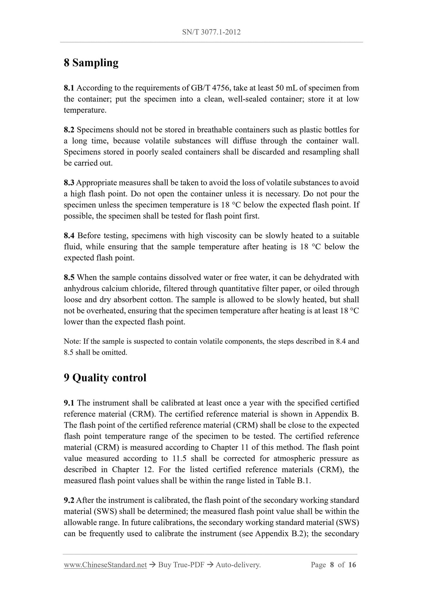
8 Sampling
8.1 According to the requirements of GB/T 4756, take at least 50 mL of specimen from
the container; put the specimen into a clean, well-sealed container; store it at low
temperature.
8.2 Specimens should not be stored in breathable containers such as plastic bottles for
a long time, because volatile substances will diffuse through the container wall.
Specimens stored in poorly sealed containers shall be discarded and resampling shall
be carried out.
8.3 Appropriate measures shall be taken to avoid the loss of volatile substances to avoid
a high flash point. Do not open the container unless it is necessary. Do not pour the
specimen unless the specimen temperature is 18 °C below the expected flash point. If
possible, the specimen shall be tested for flash point first.
8.4 Before testing, specimens with high viscosity can be slowly heated to a suitable
fluid, while ensuring that the sample temperature after heating is 18 °C below the
expected flash point.
8.5 When the sample contains dissolved water or free water, it can be dehydrated with
anhydrous calcium chloride, filtered through quantitative filter paper, or oiled through
loose and dry absorbent cotton. The sample is allowed to be slowly heated, but shall
not be overheated, ensuring that the specimen temperature after heating is at least 18 °C
lower than the expected flash point.
Note: If the sample is suspected to contain volatile components, the steps described in 8.4 and
8.5 shall be omitted.
9 Quality control
9.1 The instrument shall be calibrated at least once a year with the specified certified
reference material (CRM). The certified reference material is shown in Appendix B.
The flash point of the certified reference material (CRM) shall be close to the expected
flash point temperature range of the specimen to be tested. The certified reference
material (CRM) is measured according to Chapter 11 of this method. The flash point
value measured according to 11.5 shall be corrected for atmospheric pressure as
described in Chapter 12. For the listed certified reference materials (CRM), the
measured flash point values shall be within the range listed in Table B.1.
9.2 After the instrument is calibrated, the flash point of the secondary working standard
material (SWS) shall be determined; the measured flash point value shall be within the
allowable range. In future calibrations, the secondary working standard material (SWS)
can be frequently used to calibrate the instrument (see Appendix B.2); the secondary
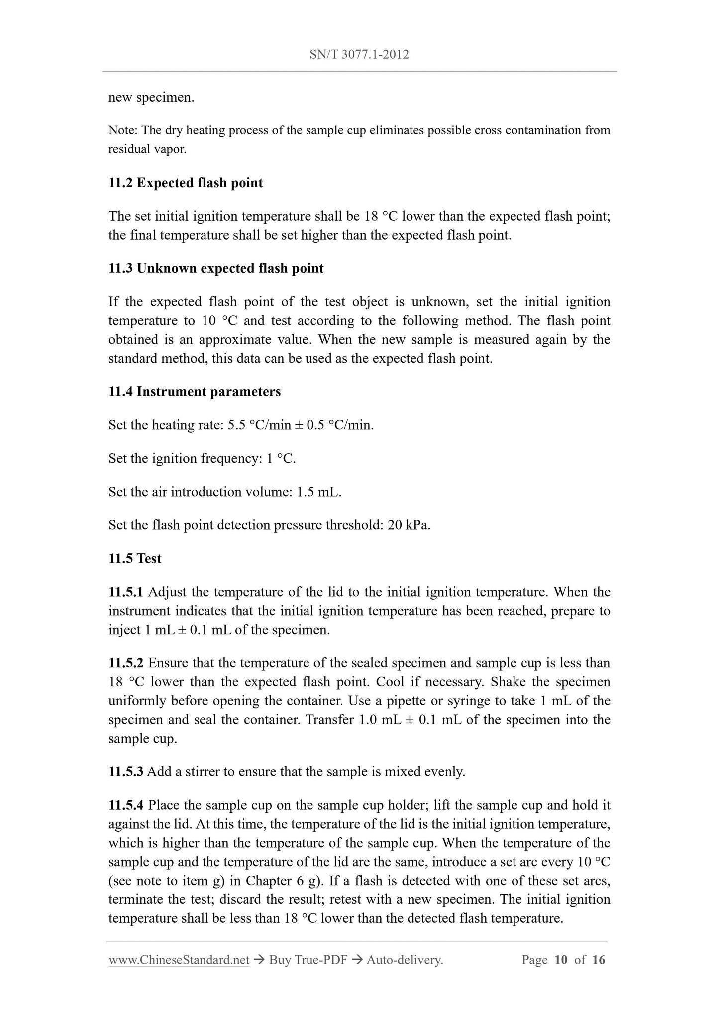
new specimen.
Note: The dry heating process of the sample cup eliminates possible cross contamination from
residual vapor.
11.2 Expected flash point
The set initial ignition temperature shall be 18 °C lower than the expected flash point;
the final temperature shall be set higher than the expected flash point.
11.3 Unknown expected flash point
If the expected flash point of the test object is unknown, set the initial ignition
temperature to 10 °C and test according to the following method. The flash point
obtained is an approximate value. When the new sample is measured again by the
standard method, this data can be used as the expected flash point.
11.4 Instrument parameters
Set the heating rate: 5.5 °C/min ± 0.5 °C/min.
Set the ignition frequency: 1 °C.
Set the air introduction volume: 1.5 mL.
Set the flash point detection pressure threshold: 20 kPa.
11.5 Test
11.5.1 Adjust the temperature of the lid to the initial ignition temperature. When the
instrument indicates that the initial ignition temperature has been reached, prepare to
inject 1 mL ± 0.1 mL of the specimen.
11.5.2 Ensure that the temperature of the sealed specimen and sample cup is less than
18 °C lower than the expected flash point. Cool if necessary. Shake the specimen
uniformly before opening the container. Use a pipette or syringe to take 1 mL of the
specimen and seal the container. Transfer 1.0 mL ± 0.1 mL of the specimen into the
sample cup.
11.5.3 Add a stirrer to ensure that the sample is mixed evenly.
11.5.4 Place the sample cup on the sample cup holder; lift the sample cup and hold it
against the lid. At this time, the temperature of the lid is the initial ignition temperature,
which is higher than the temperature of the sample cup. When the temperature of the
sample cup and the temperature of the lid are the same, introduce a set arc every 10 °C
(see note to item g) in Chapter 6 g). If a flash is detected with one of these set arcs,
terminate the test; discard the result; retest with a new specimen. The initial ignition
temperature shall be less than 18 °C lower than the detected flash temperature.
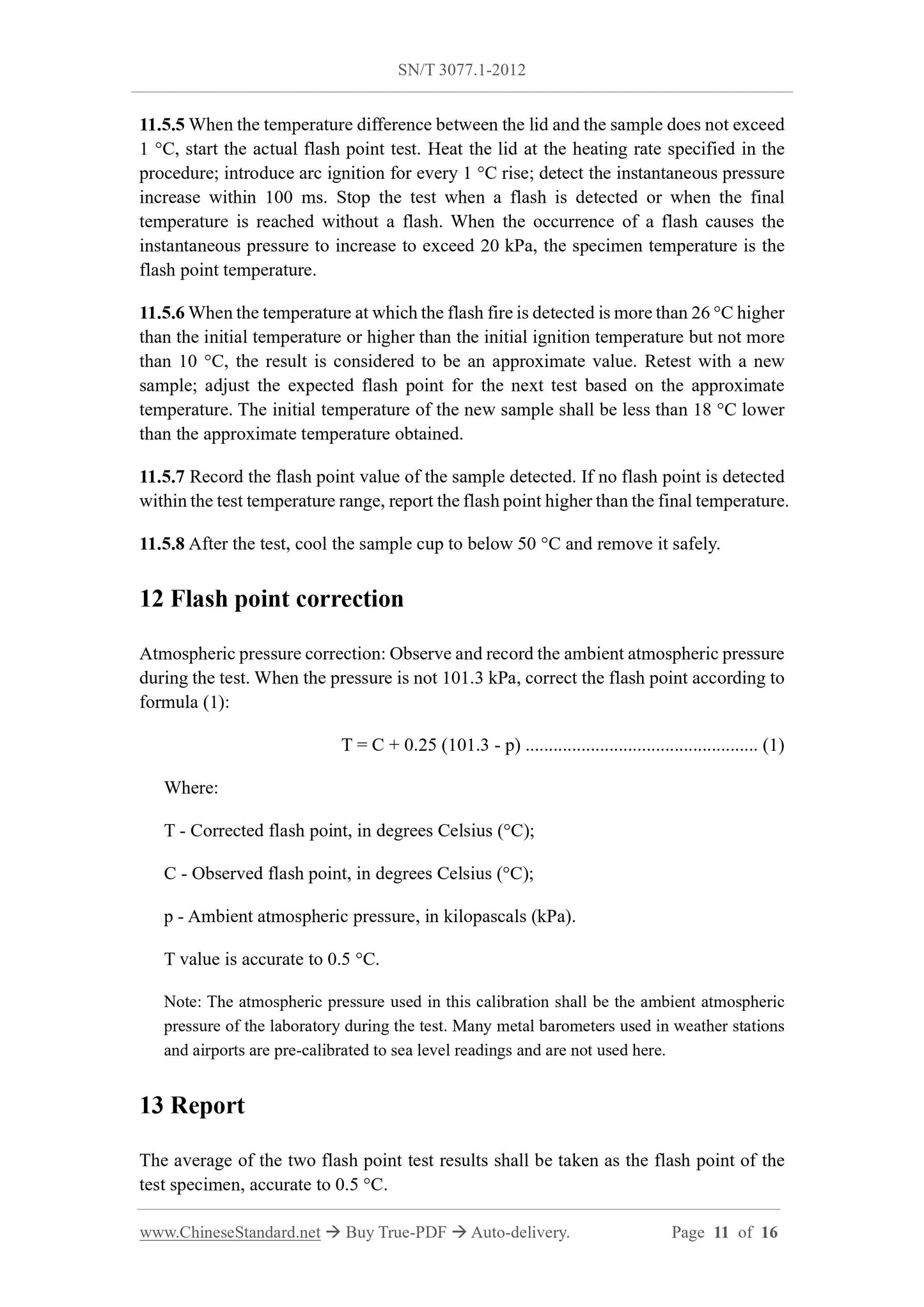
11.5.5 When the temperature difference between the lid and the sample does not exceed
1 °C, start the actual flash point test. Heat the lid at the heating rate specified in the
procedure; introduce arc ignition for every 1 °C rise; detect the instantaneous pressure
increase within 100 ms. Stop the test when a flash is detected or when the final
temperature is reached without a flash. When the occurrence of a flash causes the
instantaneous pressure to increase to exceed 20 kPa, the specimen temperature is the
flash point temperature.
11.5.6 When the temperature at which the flash fire is detected is more than 26 °C higher
than the initial temperature or higher than the initial ignition temperature but not more
than 10 °C, the result is considered to be an approximate value. Retest with a new
sample; adjust the expected flash point for the next test based on the approximate
temperature. The initial temperature of the new sample shall be less than 18 °C lower
than the approximate temperature obtained.
11.5.7 Record the flash point value of the sample detected. If no flash point is detected
within the test temperature range, report the flash point higher than the final temperature.
11.5.8 After the test, cool the sample cup to below 50 °C and remove it safely.
12 Flash point correction
Atmospheric pressure correction: Observe and record the ambient atmospheric pressure
during the test. When the pressure is not 101.3 kPa, correct the flash point according to
formula (1):
T = C + 0.25 (101.3 - p) ... (1)
Where:
T - Corrected flash point, in degrees Celsius (°C);
C - Observed flash point, in degrees Celsius (°C);
p - Ambient atmospheric pressure, in kilopascals (kPa).
T value is accurate to 0.5 °C.
Note: The atmospheric pressure used in this calibration shall be the ambient atmospheric
pressure of the laboratory during the test. Many metal barometers used in weather stations
and airports are pre-calibrated to sea level readings and are not used here.
13 Report
The average of the two flash point test results shall be taken as the flash point of the
test specimen, accurate to 0.5 °C.
Appendix B
(Informative)
Liquids used for instrument calibration
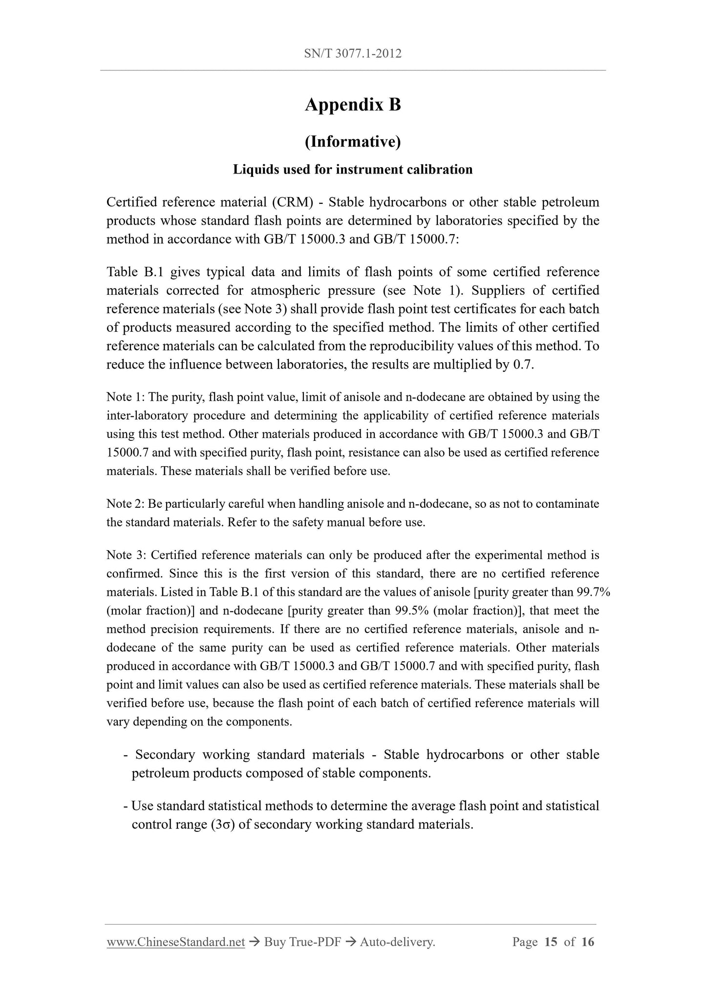
Certified reference material (CRM) - Stable hydrocarbons or other stable petroleum
products whose standard flash points are determined by laboratories specified by the
method in accordance with GB/T 15000.3 and GB/T 15000.7:
Table B.1 gives typi...
Get Quotation: Click SN/T 3077.1-2012 (Self-service in 1-minute)
Historical versions (Master-website): SN/T 3077.1-2012
Preview True-PDF (Reload/Scroll-down if blank)
SN/T 3077.1-2012: Test method for flash point by continuously closed cup tester
SN/T 3077.1-2012
SN
ENTRY-EXIT INSPECTION AND QUARANTINE INDUSTRY
STANDARD OF THE PEOPLE’S REPUBLIC OF CHINA
Test method for flash point by continuously closed cup tester
ISSUED ON: MAY 07, 2012
IMPLEMENTED ON: NOVEMBER 16, 2012
Issued by: General Administration of Quality Supervision, Inspection and
Quarantine of PRC
Table of Contents
Foreword ... 3
1 Scope ... 4
2 Normative references ... 4
3 Terms and definitions ... 4
4 Method summary ... 5
5 Significance and use ... 5
6 Equipment ... 6
7 Reagents and materials ... 7
8 Sampling ... 8
9 Quality control ... 8
10 Preparation of instruments ... 9
11 Test procedure ... 9
12 Flash point correction ... 11
13 Report ... 11
14 Precision and deviation ... 12
Appendix A (Normative) Instrument specifications ... 13
Appendix B (Informative) Liquids used for instrument calibration ... 15
Test method for flash point by continuously closed cup tester
1 Scope
This Part of SN/T 3077 specifies the method for determining the flash point of
continuously closed cup.
This Part is applicable to the determination of the flash point of fuel oil, lubricating oil,
solvent oil and other liquids; its determination range is 10 °C ~ 250 °C.
Note: Flash points below 10 °C or above 250 °C can be measured, but the precision has not
been obtained.
If the user's product requires a specified flash point test method other than this method,
neither this method nor any other method can replace the specified method without
comparative data and the approval of the specification developer.
2 Normative references
The following documents are essential to the application of this document. For the dated
documents, only the versions with the dates indicated are applicable to this document;
for the undated documents, only the latest version (including all the amendments) is
applicable to this standard.
GB/T 4756 Petroleum liquids - Manual sampling (GB/T 4756-1998, eqv ISO
3170:1988)
3 Terms and definitions
The following terms and definitions apply to this document.
3.1
Flash point
The lowest temperature (corrected to 101.3 kPa pressure) at which the vapor of the
specimen ignites under the specified test conditions.
Note 1: For the substance being tested, the flash point is not a constant physical and
chemical property, but a collection of instrumentation, instrument use, test process.
Therefore, the flash point can only be defined according to the method. The results measured
by different methods or different test instruments do not have a universally valid correlation.
Note 2: When the pressure increase caused by the hot flame in the closed test chamber is at
least 20 kPa, it is confirmed that the specimen has flashed.
3.2
Dynamic
The state when the vapor on the specimen and the specimen have not reached
temperature equilibrium when the fire source is introduced.
4 Method summary
Adjust the temperature of the test chamber lid to be less than 18 °C below the expected
flash point. Inject 1 mL ± 0.1 mL of sample into the sample cup. The temperature of the
sample and the sample cup shall be less than 18 °C below the expected flash point; it
can be cooled if necessary. Lift the sample cup and press the lid of the specified size, to
form a continuously closed but unsealed test chamber, which has a total volume of 4.0
mL ± 0.2 mL.
Close the measuring chamber; the temperature difference between the specimen and
the lid shall be within 1 °C; the lid is heated at a specified constant rate. An arc of a
certain energy is discharged in the test chamber at a specified time interval. After each
ignition, 1.5 mL ± 0.5 mL of air is introduced into the test chamber to provide the
required oxygen for the next flash test. Except for the short time when air is introduced
and when the flash point is reached, the pressure in the continuously closed but not
sealed test chamber shall be the ambient atmospheric pressure.
After each arc discharge, the pressure increase in the test chamber is detected to be
higher than the atmospheric pressure. When the pressure increase exceeds the specified
critical value, the temperature is recorded as the uncorrected flash point.
5 Significance and use
Flash point is a measure of the tendency of the specimen to form a flammable mixture
with air under specified test conditions. It is only one of the indicators for evaluating
all combustion hazards of a substance.
This test method is used to measure and describe the sensitivity of a substance to heat
and ignition sources under controlled test conditions; it cannot be used to describe and
evaluate the fire risk of a substance under actual ignition conditions.
Flash point can be used to indicate that highly volatile or flammable substances may
exist in relatively non-volatile or non-flammable substances, such as lubricating oil
containing a small amount of diesel or gasoline.
is adjusted by the electric heating and cooling of the lid; the temperature control
accuracy is ±0.2 °C.
g) High-voltage arc: The flammable vapor is ignited by a high-voltage arc. The
energy of each arc shall be 3 J ± 0.5 J (3 ws ± 0.5 ws)/arc; the arc use time is 43
ms ± 3 ms.
Note: When the specimen contains a low flash point substance or the flash point of the
specimen is lower than the initial ignition temperature, there may be supersaturated
vapor in the test chamber. Therefore, the instrument shall be designed to enable the
instrument to ignite once every 10 °C after the test chamber is closed and before the
initial ignition temperature is reached.
h) Flash point pressure test sensor: The flash point pressure test sensor shall be
connected to the connecting tube in the lid, which has an operating range of 80
kPa ~ 177 kPa, a minimum resolution of 0.1 kPa, an accuracy of ±0.5 kPa. It can
measure a transient pressure increase of at least 20 kPa above atmospheric
pressure within 100 ms.
Note 1: Detecting a transient pressure increase above atmospheric pressure is one of
several methods used to detect flash fires in the test chamber. A 20 kPa pressure increase
is equivalent to a flame volume of approximately 1.5 mL.
Note 2: An automatic pressure calibrator that performs atmospheric pressure calibration
according to the steps described in Chapter 12 can be installed in the test instrument.
Calibration can be performed using the transient pressure readings of the pressure sensor
described in this clause.
i) Pipette: Use a pipette or syringe to transfer 1.0 mL of specimen, which has an
accuracy of 0.1 mL.
7 Reagents and materials
7.1 Reagents and purity
Refer to Table B.1 for reagent purity. Reagents of other grades may be used when the
purity of the reagents used does not affect the measurement accuracy.
7.1.1 Anisole.
7.1.2 n-Dodecane.
7.2 Cleaning solvents
Only non-corrosive solvents such as toluene and acetone can be used to clean the
sample cup and lid.
8 Sampling
8.1 According to the requirements of GB/T 4756, take at least 50 mL of specimen from
the container; put the specimen into a clean, well-sealed container; store it at low
temperature.
8.2 Specimens should not be stored in breathable containers such as plastic bottles for
a long time, because volatile substances will diffuse through the container wall.
Specimens stored in poorly sealed containers shall be discarded and resampling shall
be carried out.
8.3 Appropriate measures shall be taken to avoid the loss of volatile substances to avoid
a high flash point. Do not open the container unless it is necessary. Do not pour the
specimen unless the specimen temperature is 18 °C below the expected flash point. If
possible, the specimen shall be tested for flash point first.
8.4 Before testing, specimens with high viscosity can be slowly heated to a suitable
fluid, while ensuring that the sample temperature after heating is 18 °C below the
expected flash point.
8.5 When the sample contains dissolved water or free water, it can be dehydrated with
anhydrous calcium chloride, filtered through quantitative filter paper, or oiled through
loose and dry absorbent cotton. The sample is allowed to be slowly heated, but shall
not be overheated, ensuring that the specimen temperature after heating is at least 18 °C
lower than the expected flash point.
Note: If the sample is suspected to contain volatile components, the steps described in 8.4 and
8.5 shall be omitted.
9 Quality control
9.1 The instrument shall be calibrated at least once a year with the specified certified
reference material (CRM). The certified reference material is shown in Appendix B.
The flash point of the certified reference material (CRM) shall be close to the expected
flash point temperature range of the specimen to be tested. The certified reference
material (CRM) is measured according to Chapter 11 of this method. The flash point
value measured according to 11.5 shall be corrected for atmospheric pressure as
described in Chapter 12. For the listed certified reference materials (CRM), the
measured flash point values shall be within the range listed in Table B.1.
9.2 After the instrument is calibrated, the flash point of the secondary working standard
material (SWS) shall be determined; the measured flash point value shall be within the
allowable range. In future calibrations, the secondary working standard material (SWS)
can be frequently used to calibrate the instrument (see Appendix B.2); the secondary
new specimen.
Note: The dry heating process of the sample cup eliminates possible cross contamination from
residual vapor.
11.2 Expected flash point
The set initial ignition temperature shall be 18 °C lower than the expected flash point;
the final temperature shall be set higher than the expected flash point.
11.3 Unknown expected flash point
If the expected flash point of the test object is unknown, set the initial ignition
temperature to 10 °C and test according to the following method. The flash point
obtained is an approximate value. When the new sample is measured again by the
standard method, this data can be used as the expected flash point.
11.4 Instrument parameters
Set the heating rate: 5.5 °C/min ± 0.5 °C/min.
Set the ignition frequency: 1 °C.
Set the air introduction volume: 1.5 mL.
Set the flash point detection pressure threshold: 20 kPa.
11.5 Test
11.5.1 Adjust the temperature of the lid to the initial ignition temperature. When the
instrument indicates that the initial ignition temperature has been reached, prepare to
inject 1 mL ± 0.1 mL of the specimen.
11.5.2 Ensure that the temperature of the sealed specimen and sample cup is less than
18 °C lower than the expected flash point. Cool if necessary. Shake the specimen
uniformly before opening the container. Use a pipette or syringe to take 1 mL of the
specimen and seal the container. Transfer 1.0 mL ± 0.1 mL of the specimen into the
sample cup.
11.5.3 Add a stirrer to ensure that the sample is mixed evenly.
11.5.4 Place the sample cup on the sample cup holder; lift the sample cup and hold it
against the lid. At this time, the temperature of the lid is the initial ignition temperature,
which is higher than the temperature of the sample cup. When the temperature of the
sample cup and the temperature of the lid are the same, introduce a set arc every 10 °C
(see note to item g) in Chapter 6 g). If a flash is detected with one of these set arcs,
terminate the test; discard the result; retest with a new specimen. The initial ignition
temperature shall be less than 18 °C lower than the detected flash temperature.
11.5.5 When the temperature difference between the lid and the sample does not exceed
1 °C, start the actual flash point test. Heat the lid at the heating rate specified in the
procedure; introduce arc ignition for every 1 °C rise; detect the instantaneous pressure
increase within 100 ms. Stop the test when a flash is detected or when the final
temperature is reached without a flash. When the occurrence of a flash causes the
instantaneous pressure to increase to exceed 20 kPa, the specimen temperature is the
flash point temperature.
11.5.6 When the temperature at which the flash fire is detected is more than 26 °C higher
than the initial temperature or higher than the initial ignition temperature but not more
than 10 °C, the result is considered to be an approximate value. Retest with a new
sample; adjust the expected flash point for the next test based on the approximate
temperature. The initial temperature of the new sample shall be less than 18 °C lower
than the approximate temperature obtained.
11.5.7 Record the flash point value of the sample detected. If no flash point is detected
within the test temperature range, report the flash point higher than the final temperature.
11.5.8 After the test, cool the sample cup to below 50 °C and remove it safely.
12 Flash point correction
Atmospheric pressure correction: Observe and record the ambient atmospheric pressure
during the test. When the pressure is not 101.3 kPa, correct the flash point according to
formula (1):
T = C + 0.25 (101.3 - p) ... (1)
Where:
T - Corrected flash point, in degrees Celsius (°C);
C - Observed flash point, in degrees Celsius (°C);
p - Ambient atmospheric pressure, in kilopascals (kPa).
T value is accurate to 0.5 °C.
Note: The atmospheric pressure used in this calibration shall be the ambient atmospheric
pressure of the laboratory during the test. Many metal barometers used in weather stations
and airports are pre-calibrated to sea level readings and are not used here.
13 Report
The average of the two flash point test results shall be taken as the flash point of the
test specimen, accurate to 0.5 °C.
Appendix B
(Informative)
Liquids used for instrument calibration
Certified reference material (CRM) - Stable hydrocarbons or other stable petroleum
products whose standard flash points are determined by laboratories specified by the
method in accordance with GB/T 15000.3 and GB/T 15000.7:
Table B.1 gives typi...
Share