1
/
dari
12
PayPal, credit cards. Download editable-PDF & invoice in 1 second!
QC/T 664-2019 English PDF (QCT664-2019)
QC/T 664-2019 English PDF (QCT664-2019)
Harga reguler
$265.00 USD
Harga reguler
Harga obral
$265.00 USD
Harga satuan
/
per
Biaya pengiriman dihitung saat checkout.
Tidak dapat memuat ketersediaan pengambilan
Delivery: 3 seconds. Download true-PDF + Invoice.
Get QUOTATION in 1-minute: Click QC/T 664-2019
Historical versions: QC/T 664-2019
Preview True-PDF (Reload/Scroll if blank)
QC/T 664-2019: Automotive air-conditioning refrigerant hose
QC/T 664-2019
AUTOMOBILE INDUSTRY STANDARD
OF THE PEOPLE’S REPUBLIC OF CHINA
ICS 43.040.60
T 26
Replacing QC/T 664-2000
Automotive air-conditioning refrigerant hose
ISSUED ON: DECEMBER 24, 2019
IMPLEMENTED ON: JULY 01, 2020
Issued by: Ministry of Industry and Information Technology of PRC
Table of Contents
Foreword ... 5
1 Scope ... 7
2 Normative references ... 7
3 Terms and definitions... 7
4 Categories ... 8
5 Technical requirements ... 9
6 Test methods ... 12
7 Signs ... 23
8 Inspection, packaging, transportation, storage ... 23
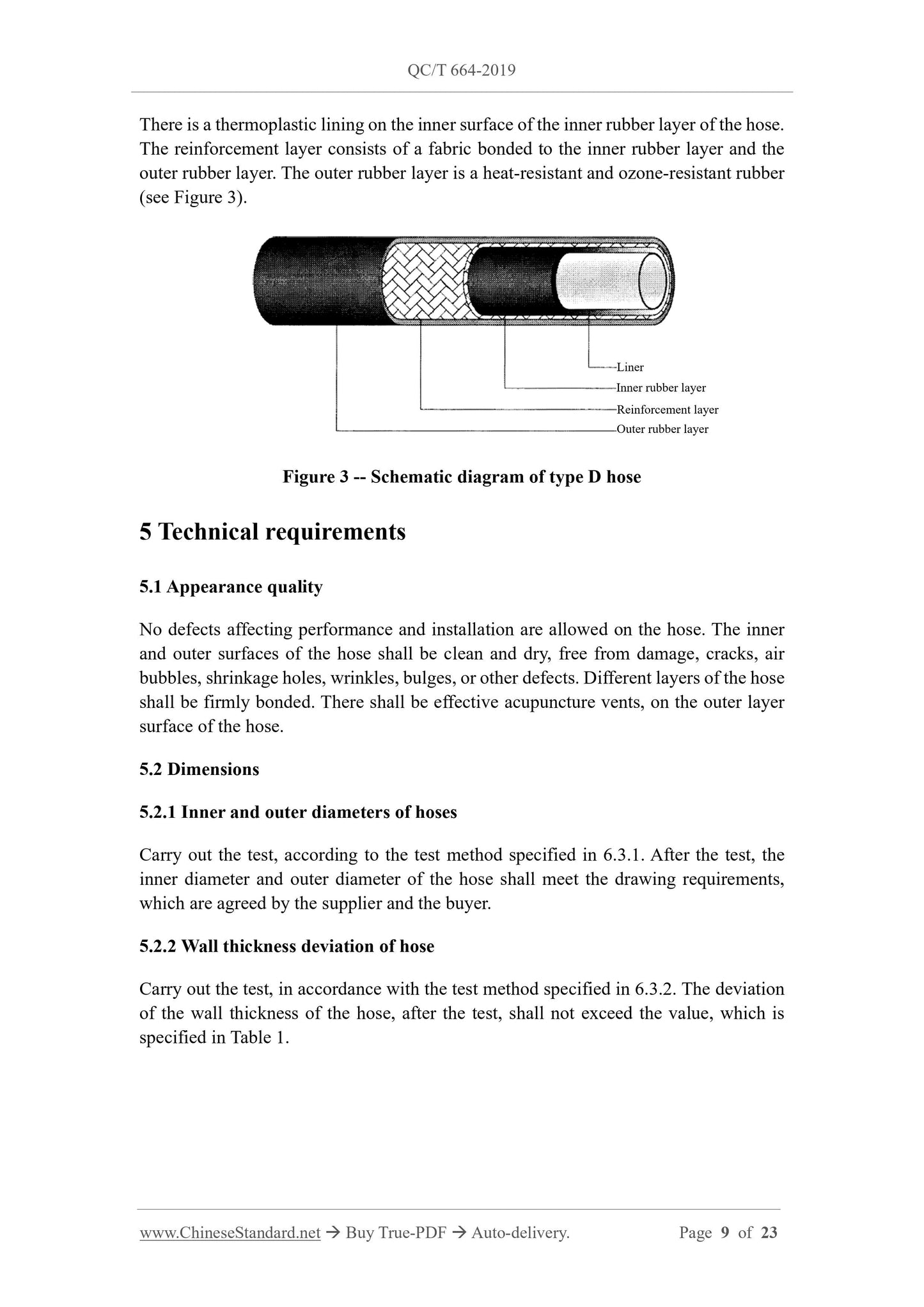
Automotive air-conditioning refrigerant hose
1 Scope
This standard specifies the classification, dimensions, technical requirements, test
methods, marking, inspection and packaging, transportation, storage of hoses for
conveying refrigerants in automotive air-conditioning systems.
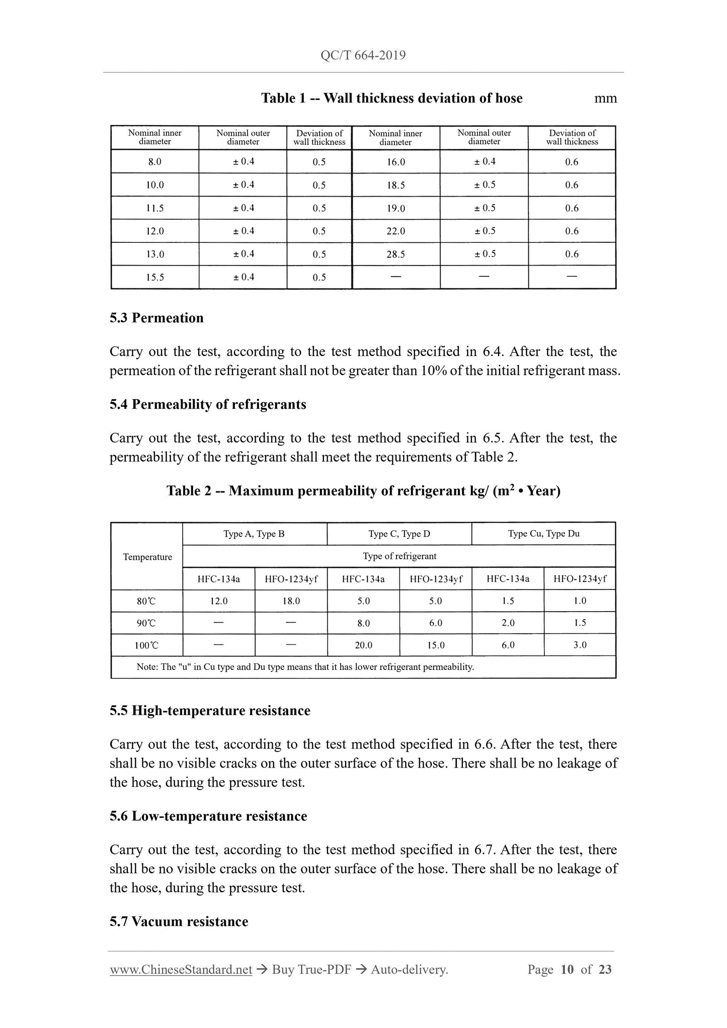
This standard is applicable to rubber or thermoplastic hoses, for conveying liquid or
gaseous HFC-134a/HFO-1234yf refrigerants in automotive air-conditioning systems.
2 Normative references
The following documents are essential for the application of this document. For dated
references, only the dated version applies to this document. For undated references, the
latest edition (including all amendments) applies to this document.
GB/T 1690 Rubber, vulcanized or thermoplastic - Determination of the effect of
liquids
GB/T 2941 Rubber - General procedures for preparing and conditioning test pieces
for physical test methods
GB/T 30512 Requirements for prohibited substances on automobiles
3 Terms and definitions
The following terms and definitions apply to this standard.
3.1
High pressure hose
A hose, which has a working pressure of not less than 3.5 MPa (marked as HP).
3.2
Low pressure hose
A hose, which has a working pressure not higher than 1.5 MPa (marked as LP).
Carry out the test, according to the test method specified in 6.8. The collapse of the
outer diameter of the hose, during the test, shall not be less than 20% of the initial outer
diameter of the hose.
5.8 Length change rate
Carry out the test, according to the test method specified in 6.9. During the test, under
the action of the specified pressure, the length change rate of the hose shall be -4% ~
2%.
5.9 Burst pressure
Carry out the test, according to the test method specified in 6.10. The minimum burst
pressure of the hose, which has a nominal inner diameter not greater than 13.0 mm,
shall be 14.7 MPa. The minimum burst pressure of the hose, which has a nominal inner
diameter greater than 13.0 mm, shall be 12.0 MPa.
5.10 Pressure resistance
Carry out the test, according to the test method specified in 6.11. During the test, the
hose shall be tested, according to the specified pressure and time. The abnormal
phenomena, such as leakage, crack, sudden twisting of the hose, are not allowed.
5.11 Extractables content
Carry out the test, according to the test method specified in 6.12. After the test, the
content of extractables, on the inner surface of the hose, shall not exceed 118 g/m2.
5.12 Volume change rate of inner layer material
Carry out the test, according to the test method specified in 6.13. After the test, the
volume change rate of the rubber material shall be -5% ~ 35%; the volume change rate
of the thermoplastic material shall be -5% ~ 5%.
5.13 Ozone resistance
Carry out the test, according to the test method specified in 6.14. After the test, the outer
rubber layer of the hose shall have no visible cracks, under an eight-fold magnifying
glass.
5.14 Internal surface cleanliness
Carry out the test, according to the test method specified in 6.15. After the test, the
impurity content shall not exceed 270 mg/m2; the size of the gas particles shall not
exceed 0.5 mm x 1.0 mm.
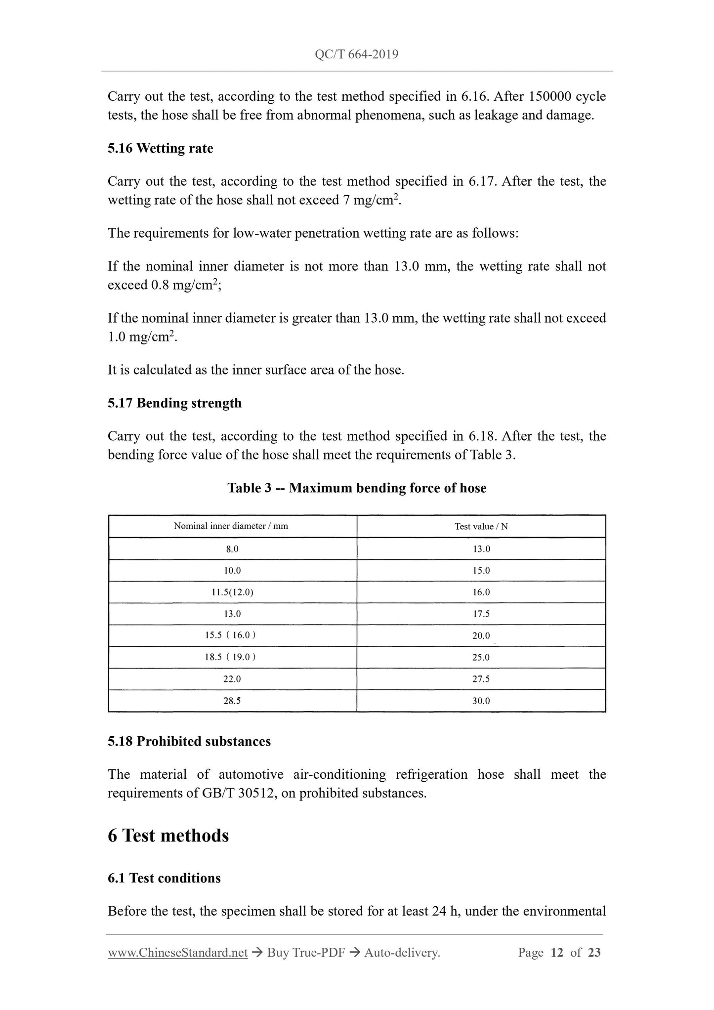
5.15 Pulse fatigue resistance
conditions specified in GB/T 2941.
6.2 Test medium
The test medium used in the test shall be a mixture of HFC-134a, which has a mass
fraction of 90% or HFO-1234yf refrigerant and 10% refrigerating machine oil.
6.3 Dimensional measurement
6.3.1 Inner and outer diameters of hoses
The inner diameter of the hose shall be measured by a special measuring tool, such as
a tapered plug gauge, expanding ball type or retractable meter, etc. The diameter is
measured 3 times; the results are averaged.
6.3.2 Deviation of hose's wall thickness
The deviation of wall thickness of the hose shall be measured by a special meter, such
as a caliper with a probe that can touch the inner wall of the hose. Measure the wall
thickness of the cross section of the hose, at four points; take the difference between the
maximum value and the minimum value measured. Make 3 measurements. Take the
average of the results.
6.4 Permeation
Take 3 hoses. Fill the hoses with the specified test medium, according to the method in
6.5.3.1. Weigh the hoses and accessories. Then place the samples at a temperature of
100 °C ± 2 °C, for 24 hours. After taking out, weigh the mass of the hose and accessories
again. Calculate the mass loss.
6.5 Refrigerant permeability
6.5.1 Test device
6.5.1.1 Accessories and fixtures
Accessories and clamps shall be sealed and leak-free, when subjected to the pressure in
the hose.
6.5.1.2 Leak detector
The sensitivity of the leak detector shall be higher than 2 g/year (under the same volume
and temperature conditions, the refrigerant's equivalent ratio HFC-134a:HFO-1234yf =
1:0.92).
6.5.1.3 Constant temperature chamber
The control accuracy of the constant temperature chamber shall be ±2 °C.
6.5.1.4 Balances
The measurement accuracy of the balance shall be 0.01 g.
6.5.2 Test conditions
For use of hoses at higher working pressures, the test temperature shall be 90 °C ± 2 °C
or 100 °C ± 2 °C (high-pressure hose). For use of hoses at lower working pressures, the
test temperature shall be 80 °C ± 2 °C (low-pressure hose).
6.5.3 Test method
6.5.3.1 Preparation before the test
Take 4 hoses, which have an exposed length of 1m, and accessories. Use seals to seal
them at both ends. Three of them are used to measure the loss of refrigerant; the fourth
one is connected with a joint, which is used as a comparison hose, to detect the change
of the mass torsion of the hose itself. In the standard state, measure the exposed length
of the hose (L1, L2), the accuracy is required to be ±1 mm. Weigh the mass of each hose
and accessories (including joints), which is required to be accurate to ± 0.1 g. The hose
assembly is filled with 0.6 mg of test medium per millimeter volume; the filling volume
is accurate to ±5 g. The number of filled hoses is 3. Use a leak detector, to check that
each hose is leaking.
Filling of refrigerant
Method 1:
Before filling the hoses and accessories, they must be kept in a low temperature
chamber of -30 °C or lower, for 4 hours. Use the density of the test medium, at this
temperature, to calculate the mass of the test medium to be filled. Keep the test medium
and the hose at this temperature Use an electronic balance, to weigh the test medium.
Then fill the test medium into the hose. The filled hose and accessories are sealed at
this temperature.
Method 2:
The hose and accessories are filled with the test medium, under a certain pressure, at
ambient temperature. The device, to keep the test medium flowing, has a storage
compressed air system, a piston pump, a device for controlling and measuring the flow.
6.5.3....
Get QUOTATION in 1-minute: Click QC/T 664-2019
Historical versions: QC/T 664-2019
Preview True-PDF (Reload/Scroll if blank)
QC/T 664-2019: Automotive air-conditioning refrigerant hose
QC/T 664-2019
AUTOMOBILE INDUSTRY STANDARD
OF THE PEOPLE’S REPUBLIC OF CHINA
ICS 43.040.60
T 26
Replacing QC/T 664-2000
Automotive air-conditioning refrigerant hose
ISSUED ON: DECEMBER 24, 2019
IMPLEMENTED ON: JULY 01, 2020
Issued by: Ministry of Industry and Information Technology of PRC
Table of Contents
Foreword ... 5
1 Scope ... 7
2 Normative references ... 7
3 Terms and definitions... 7
4 Categories ... 8
5 Technical requirements ... 9
6 Test methods ... 12
7 Signs ... 23
8 Inspection, packaging, transportation, storage ... 23
Automotive air-conditioning refrigerant hose
1 Scope
This standard specifies the classification, dimensions, technical requirements, test
methods, marking, inspection and packaging, transportation, storage of hoses for
conveying refrigerants in automotive air-conditioning systems.
This standard is applicable to rubber or thermoplastic hoses, for conveying liquid or
gaseous HFC-134a/HFO-1234yf refrigerants in automotive air-conditioning systems.
2 Normative references
The following documents are essential for the application of this document. For dated
references, only the dated version applies to this document. For undated references, the
latest edition (including all amendments) applies to this document.
GB/T 1690 Rubber, vulcanized or thermoplastic - Determination of the effect of
liquids
GB/T 2941 Rubber - General procedures for preparing and conditioning test pieces
for physical test methods
GB/T 30512 Requirements for prohibited substances on automobiles
3 Terms and definitions
The following terms and definitions apply to this standard.
3.1
High pressure hose
A hose, which has a working pressure of not less than 3.5 MPa (marked as HP).
3.2
Low pressure hose
A hose, which has a working pressure not higher than 1.5 MPa (marked as LP).
Carry out the test, according to the test method specified in 6.8. The collapse of the
outer diameter of the hose, during the test, shall not be less than 20% of the initial outer
diameter of the hose.
5.8 Length change rate
Carry out the test, according to the test method specified in 6.9. During the test, under
the action of the specified pressure, the length change rate of the hose shall be -4% ~
2%.
5.9 Burst pressure
Carry out the test, according to the test method specified in 6.10. The minimum burst
pressure of the hose, which has a nominal inner diameter not greater than 13.0 mm,
shall be 14.7 MPa. The minimum burst pressure of the hose, which has a nominal inner
diameter greater than 13.0 mm, shall be 12.0 MPa.
5.10 Pressure resistance
Carry out the test, according to the test method specified in 6.11. During the test, the
hose shall be tested, according to the specified pressure and time. The abnormal
phenomena, such as leakage, crack, sudden twisting of the hose, are not allowed.
5.11 Extractables content
Carry out the test, according to the test method specified in 6.12. After the test, the
content of extractables, on the inner surface of the hose, shall not exceed 118 g/m2.
5.12 Volume change rate of inner layer material
Carry out the test, according to the test method specified in 6.13. After the test, the
volume change rate of the rubber material shall be -5% ~ 35%; the volume change rate
of the thermoplastic material shall be -5% ~ 5%.
5.13 Ozone resistance
Carry out the test, according to the test method specified in 6.14. After the test, the outer
rubber layer of the hose shall have no visible cracks, under an eight-fold magnifying
glass.
5.14 Internal surface cleanliness
Carry out the test, according to the test method specified in 6.15. After the test, the
impurity content shall not exceed 270 mg/m2; the size of the gas particles shall not
exceed 0.5 mm x 1.0 mm.
5.15 Pulse fatigue resistance
conditions specified in GB/T 2941.
6.2 Test medium
The test medium used in the test shall be a mixture of HFC-134a, which has a mass
fraction of 90% or HFO-1234yf refrigerant and 10% refrigerating machine oil.
6.3 Dimensional measurement
6.3.1 Inner and outer diameters of hoses
The inner diameter of the hose shall be measured by a special measuring tool, such as
a tapered plug gauge, expanding ball type or retractable meter, etc. The diameter is
measured 3 times; the results are averaged.
6.3.2 Deviation of hose's wall thickness
The deviation of wall thickness of the hose shall be measured by a special meter, such
as a caliper with a probe that can touch the inner wall of the hose. Measure the wall
thickness of the cross section of the hose, at four points; take the difference between the
maximum value and the minimum value measured. Make 3 measurements. Take the
average of the results.
6.4 Permeation
Take 3 hoses. Fill the hoses with the specified test medium, according to the method in
6.5.3.1. Weigh the hoses and accessories. Then place the samples at a temperature of
100 °C ± 2 °C, for 24 hours. After taking out, weigh the mass of the hose and accessories
again. Calculate the mass loss.
6.5 Refrigerant permeability
6.5.1 Test device
6.5.1.1 Accessories and fixtures
Accessories and clamps shall be sealed and leak-free, when subjected to the pressure in
the hose.
6.5.1.2 Leak detector
The sensitivity of the leak detector shall be higher than 2 g/year (under the same volume
and temperature conditions, the refrigerant's equivalent ratio HFC-134a:HFO-1234yf =
1:0.92).
6.5.1.3 Constant temperature chamber
The control accuracy of the constant temperature chamber shall be ±2 °C.
6.5.1.4 Balances
The measurement accuracy of the balance shall be 0.01 g.
6.5.2 Test conditions
For use of hoses at higher working pressures, the test temperature shall be 90 °C ± 2 °C
or 100 °C ± 2 °C (high-pressure hose). For use of hoses at lower working pressures, the
test temperature shall be 80 °C ± 2 °C (low-pressure hose).
6.5.3 Test method
6.5.3.1 Preparation before the test
Take 4 hoses, which have an exposed length of 1m, and accessories. Use seals to seal
them at both ends. Three of them are used to measure the loss of refrigerant; the fourth
one is connected with a joint, which is used as a comparison hose, to detect the change
of the mass torsion of the hose itself. In the standard state, measure the exposed length
of the hose (L1, L2), the accuracy is required to be ±1 mm. Weigh the mass of each hose
and accessories (including joints), which is required to be accurate to ± 0.1 g. The hose
assembly is filled with 0.6 mg of test medium per millimeter volume; the filling volume
is accurate to ±5 g. The number of filled hoses is 3. Use a leak detector, to check that
each hose is leaking.
Filling of refrigerant
Method 1:
Before filling the hoses and accessories, they must be kept in a low temperature
chamber of -30 °C or lower, for 4 hours. Use the density of the test medium, at this
temperature, to calculate the mass of the test medium to be filled. Keep the test medium
and the hose at this temperature Use an electronic balance, to weigh the test medium.
Then fill the test medium into the hose. The filled hose and accessories are sealed at
this temperature.
Method 2:
The hose and accessories are filled with the test medium, under a certain pressure, at
ambient temperature. The device, to keep the test medium flowing, has a storage
compressed air system, a piston pump, a device for controlling and measuring the flow.
6.5.3....
Share