1
/
of
12
PayPal, credit cards. Download editable-PDF & invoice in 1 second!
QC/T 520-2019 English PDF (QCT520-2019)
QC/T 520-2019 English PDF (QCT520-2019)
Regular price
$325.00 USD
Regular price
Sale price
$325.00 USD
Unit price
/
per
Shipping calculated at checkout.
Couldn't load pickup availability
Delivery: 3 seconds. Download true-PDF + Invoice.
Get QUOTATION in 1-minute: Click QC/T 520-2019
Historical versions: QC/T 520-2019
Preview True-PDF (Reload/Scroll if blank)
QC/T 520-2019: Sample scaling test method for automotive friction material
QC/T 520-2019
QC
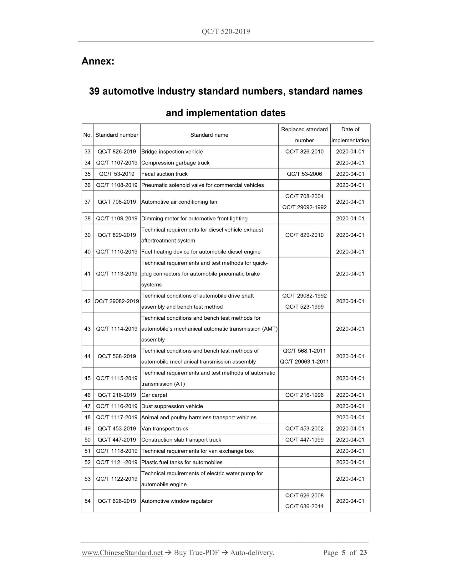
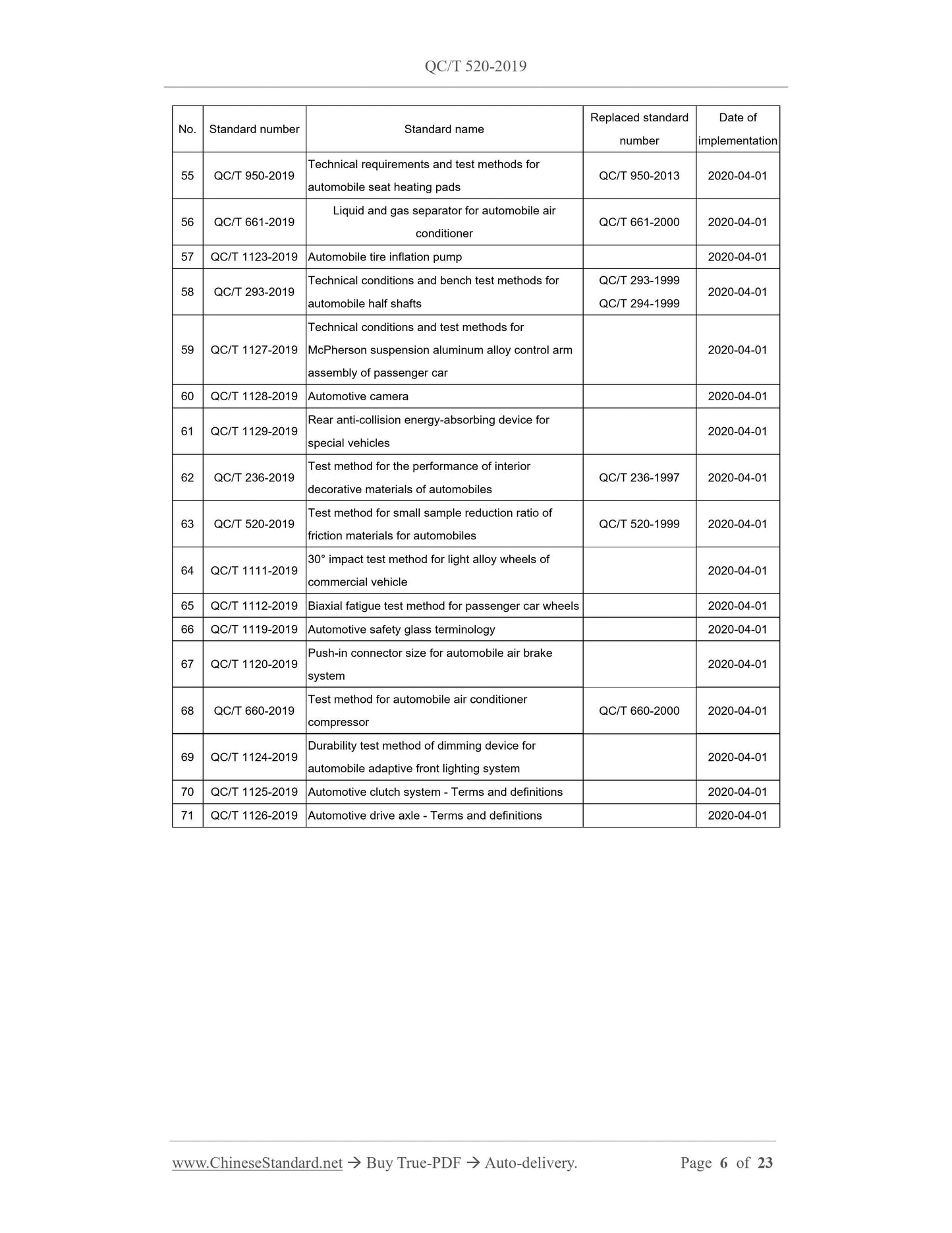
AUTOMOBILE INDUSTRY STANDARD
OF THE PEOPLE’S REPUBLIC OF CHINA
ICS 43.040.40
T 24
Replacing QC/T 520-1999
Sample scaling test method for automotive friction material
ISSUED ON: NOVEMBER 11, 2019
IMPLEMENTED ON: APRIL 01, 2020
Issued by: Ministry of Industry and Information Technology of PRC
Table of Contents
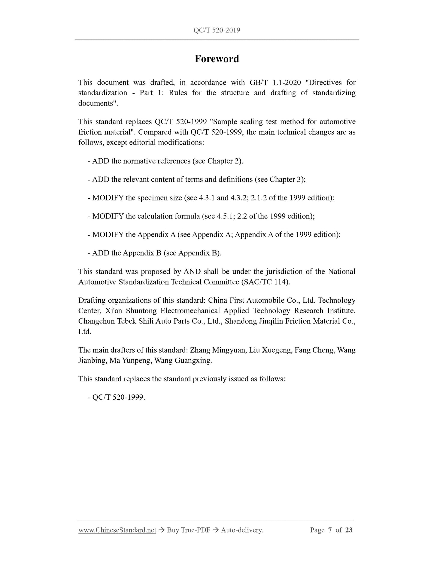
Foreword ... 7
1 Scope ... 8
2 Normative references ... 8
3 Terms and definitions ... 8
4 Test method ... 9
5 Test procedure ... 16
Appendix A (Normative) Test program ... 21
Appendix B (Normative) Test record ... 23
Sample scaling test method for automotive friction material
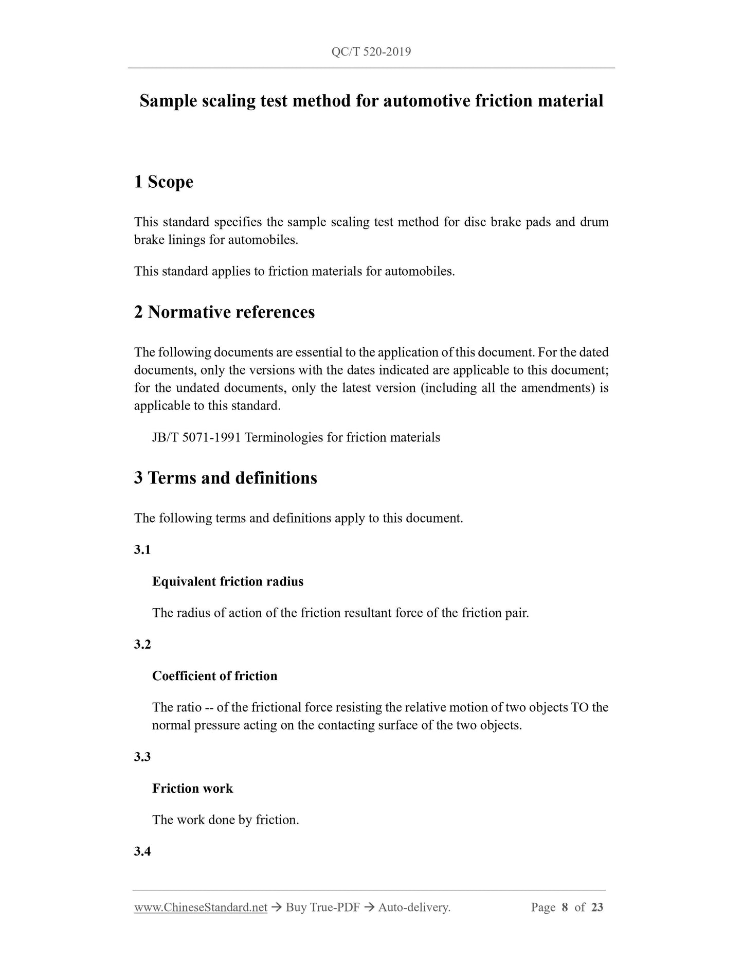
1 Scope
This standard specifies the sample scaling test method for disc brake pads and drum
brake linings for automobiles.
This standard applies to friction materials for automobiles.
2 Normative references
The following documents are essential to the application of this document. For the dated
documents, only the versions with the dates indicated are applicable to this document;
for the undated documents, only the latest version (including all the amendments) is
applicable to this standard.
JB/T 5071-1991 Terminologies for friction materials
3 Terms and definitions
The following terms and definitions apply to this document.
3.1
Equivalent friction radius
The radius of action of the friction resultant force of the friction pair.
3.2
Coefficient of friction
The ratio -- of the frictional force resisting the relative motion of two objects TO the
normal pressure acting on the contacting surface of the two objects.
3.3
Friction work
The work done by friction.
3.4
Mass wear
The ratio -- of mass wear TO total average friction work, under specified conditions.
3.5
Volume wear
The ratio -- of the volumetric wear TO the total average friction work, under
specified conditions.
3.6
Average braking torque
The ratio -- of the area covered by each braking torque versus time curve TO the
effective braking time.
3.7
Friction torque stability coefficient
The ratio -- of the average braking torque to the maximum braking torque for each
braking.
3.8
Area reducing scale ratio
The ratio -- of the total area of a single brake friction material TO the total area of a
sample friction material.
3.9
Radius reducing scale ratio
The ratio -- of the equivalent friction radius of the brake TO the effective radius of
the specimen.
[JB/T 5071-1991, definition 4.24, definition 4.25]
4 Test method
4.1 Test equipment
4.1.1 The performance indicators of the inertia brake testing machine shall meet the
requirements of various tests.
n0 - Initial test speed, r/min;
nt - Braking end speed, r/min;
Kr - Radius reducing scale ratio;
t - Braking time, s.
4.5.2 Adjust the test equipment, to make it in normal working condition.
4.5.3 The specimen shall be installed on the fixed end. The gap with the test pair shall
be adjusted to 0.4 mm ~ 0.6 mm. The test pair shall rotate during the test.
4.5.4 Before each test, the test inertia, brake speed, test specific pressure, brake
temperature shall be adjusted, according to different vehicle models. All test parameters
shall be input accurately.
4.5.5 The temperature of the friction surface is measured by a thermocouple, which is
welded with "Nickle-aluminum-nickel-chromium". The thermocouple must be inserted
along the effective radius of the specimen to a depth of 4 mm ~ 6 mm AND 0.5 mm
away from the friction surface.
5 Test procedure
5.1 First run-in
The first run-in requirements are as follows:
a) Take the driving speed (Va) of the vehicle as 50 km/h; calculate the initial test
speed (n0) according to formula (10);
b) Take the vehicle braking deceleration (a) as 3.0 m/s2; calculate the test specific
pressure (P0) according to formula (12);
c) During the run-in process, the initial temperature of each braking shall not exceed
100 °C;
d) The number of braking shall be such that the contacting area of ring specimen is
ground to reach above 90%, then stop run-in; however, the number of braking
shall be not less than 10.
e) Record the pressure, torque, temperature, rotational speed during braking.
5.2 First measurement
The first measurement requires the following:
a) Use a micrometer, which has a precision 0.01 mm, to measure and record the
thickness of the ring specimen and the marked three points of the test pair, to
calculate the volume wear. If the mass wear needs to be calculated, use a balance,
which has an accuracy of not less than 0.01 g, to measure and record the friction
pair mass;
b) The friction pair shall be measured after cooling to room temperature.
5.3 The first friction torque test
The requirements for the first friction torque test are as follows:
a) For drum brake lining ring specimens, the vehicle speeds (Va) are respectively 50
km/h, 70 km/h, 90 km/h; for disc brake pad ring specimens, the vehicle speeds
(Va) are respectively 80 km/h, 120 km/h, 160 km/h. Calculate the initial test speed
(n0) according to formula (10);
b) Test specific pressure (P0) shall be 0.30 MPa, 0.40 MPa, 0.60 MPa, 0.80 MPa,
1.00 MPa, 1.20 MPa, respectively;
c) The braking cycle is based on the fact that the initial temperature of each braking
does not exceed 100 °C;
d) Brake once at each test speed and each test specific pressure; each brake is from
the initial test speed (n0) of the brake to the brake stop.
e) Record the pressure, torque, temperature, rotational speed during braking.
5.4 First recession and recovery test
5.4.1 Benchmark test
The benchmark test requirements are as follows:
a) Take the vehicle braking deceleration (a) as 4.5 m/s2. Calculate the initial test
speed (n0), according to formula (10). Calculate the test specific pressure (P0),
according to formula (12). For drum brake lining ring specimens, the vehicle
speed (Va) is 50 km/h and 70 km/h; for disc brake pad ring specimens, the vehicle
speed (Va) is 80 km/h and 120 km/h. Braking is performed 3 times at each speed,
as a baseline test in the fading test.
b) Record the pressure, torque, temperature, rotational speed during braking.
5.4.2 The first recession test
The requirements for the first recession test are as follows:
a) Calculate the initial test speed (n0), according to formula (10). For the drum brake
c) Drag and brake for 25 s; then disengage for 35 s, a total of 60 s forms a braking
cycle; a total of 30 braking cycle tests are carried out;
d) The initial temperature of drag brake is 65 °C ± 5 °C.
e) Record the pressure, torque, temperature, rotational speed during braking.
5.7 The second run-in test
It is carried out according to the provisions of 5.1, to apply 50 brakes.
5.8 The third friction torque test
It is carried out according to the provisions of 5.3.
5.9 The second measurement
It is carried out according to the provisions of 5.2.
5.10 Wear rate test
The wear rate test requirements are as follows:
a) Carry out three wear tests in total. Take the vehicle braking deceleration (a) as 3.0
m/s2. Calculate the test specific pressure (P0), according to formula (12).
b) The first wear test: Calculate the initial test speed (n0) according to formula (10).
For the drum brake lining ring specimen, take the vehicle speed (Va) as 50 km/h;
for the disc brake pad ring specimen, take the vehicle speed (Va) as 80 km/h. The
initial temperature of each braking is 80 ...
Get QUOTATION in 1-minute: Click QC/T 520-2019
Historical versions: QC/T 520-2019
Preview True-PDF (Reload/Scroll if blank)
QC/T 520-2019: Sample scaling test method for automotive friction material
QC/T 520-2019
QC
AUTOMOBILE INDUSTRY STANDARD
OF THE PEOPLE’S REPUBLIC OF CHINA
ICS 43.040.40
T 24
Replacing QC/T 520-1999
Sample scaling test method for automotive friction material
ISSUED ON: NOVEMBER 11, 2019
IMPLEMENTED ON: APRIL 01, 2020
Issued by: Ministry of Industry and Information Technology of PRC
Table of Contents
Foreword ... 7
1 Scope ... 8
2 Normative references ... 8
3 Terms and definitions ... 8
4 Test method ... 9
5 Test procedure ... 16
Appendix A (Normative) Test program ... 21
Appendix B (Normative) Test record ... 23
Sample scaling test method for automotive friction material
1 Scope
This standard specifies the sample scaling test method for disc brake pads and drum
brake linings for automobiles.
This standard applies to friction materials for automobiles.
2 Normative references
The following documents are essential to the application of this document. For the dated
documents, only the versions with the dates indicated are applicable to this document;
for the undated documents, only the latest version (including all the amendments) is
applicable to this standard.
JB/T 5071-1991 Terminologies for friction materials
3 Terms and definitions
The following terms and definitions apply to this document.
3.1
Equivalent friction radius
The radius of action of the friction resultant force of the friction pair.
3.2
Coefficient of friction
The ratio -- of the frictional force resisting the relative motion of two objects TO the
normal pressure acting on the contacting surface of the two objects.
3.3
Friction work
The work done by friction.
3.4
Mass wear
The ratio -- of mass wear TO total average friction work, under specified conditions.
3.5
Volume wear
The ratio -- of the volumetric wear TO the total average friction work, under
specified conditions.
3.6
Average braking torque
The ratio -- of the area covered by each braking torque versus time curve TO the
effective braking time.
3.7
Friction torque stability coefficient
The ratio -- of the average braking torque to the maximum braking torque for each
braking.
3.8
Area reducing scale ratio
The ratio -- of the total area of a single brake friction material TO the total area of a
sample friction material.
3.9
Radius reducing scale ratio
The ratio -- of the equivalent friction radius of the brake TO the effective radius of
the specimen.
[JB/T 5071-1991, definition 4.24, definition 4.25]
4 Test method
4.1 Test equipment
4.1.1 The performance indicators of the inertia brake testing machine shall meet the
requirements of various tests.
n0 - Initial test speed, r/min;
nt - Braking end speed, r/min;
Kr - Radius reducing scale ratio;
t - Braking time, s.
4.5.2 Adjust the test equipment, to make it in normal working condition.
4.5.3 The specimen shall be installed on the fixed end. The gap with the test pair shall
be adjusted to 0.4 mm ~ 0.6 mm. The test pair shall rotate during the test.
4.5.4 Before each test, the test inertia, brake speed, test specific pressure, brake
temperature shall be adjusted, according to different vehicle models. All test parameters
shall be input accurately.
4.5.5 The temperature of the friction surface is measured by a thermocouple, which is
welded with "Nickle-aluminum-nickel-chromium". The thermocouple must be inserted
along the effective radius of the specimen to a depth of 4 mm ~ 6 mm AND 0.5 mm
away from the friction surface.
5 Test procedure
5.1 First run-in
The first run-in requirements are as follows:
a) Take the driving speed (Va) of the vehicle as 50 km/h; calculate the initial test
speed (n0) according to formula (10);
b) Take the vehicle braking deceleration (a) as 3.0 m/s2; calculate the test specific
pressure (P0) according to formula (12);
c) During the run-in process, the initial temperature of each braking shall not exceed
100 °C;
d) The number of braking shall be such that the contacting area of ring specimen is
ground to reach above 90%, then stop run-in; however, the number of braking
shall be not less than 10.
e) Record the pressure, torque, temperature, rotational speed during braking.
5.2 First measurement
The first measurement requires the following:
a) Use a micrometer, which has a precision 0.01 mm, to measure and record the
thickness of the ring specimen and the marked three points of the test pair, to
calculate the volume wear. If the mass wear needs to be calculated, use a balance,
which has an accuracy of not less than 0.01 g, to measure and record the friction
pair mass;
b) The friction pair shall be measured after cooling to room temperature.
5.3 The first friction torque test
The requirements for the first friction torque test are as follows:
a) For drum brake lining ring specimens, the vehicle speeds (Va) are respectively 50
km/h, 70 km/h, 90 km/h; for disc brake pad ring specimens, the vehicle speeds
(Va) are respectively 80 km/h, 120 km/h, 160 km/h. Calculate the initial test speed
(n0) according to formula (10);
b) Test specific pressure (P0) shall be 0.30 MPa, 0.40 MPa, 0.60 MPa, 0.80 MPa,
1.00 MPa, 1.20 MPa, respectively;
c) The braking cycle is based on the fact that the initial temperature of each braking
does not exceed 100 °C;
d) Brake once at each test speed and each test specific pressure; each brake is from
the initial test speed (n0) of the brake to the brake stop.
e) Record the pressure, torque, temperature, rotational speed during braking.
5.4 First recession and recovery test
5.4.1 Benchmark test
The benchmark test requirements are as follows:
a) Take the vehicle braking deceleration (a) as 4.5 m/s2. Calculate the initial test
speed (n0), according to formula (10). Calculate the test specific pressure (P0),
according to formula (12). For drum brake lining ring specimens, the vehicle
speed (Va) is 50 km/h and 70 km/h; for disc brake pad ring specimens, the vehicle
speed (Va) is 80 km/h and 120 km/h. Braking is performed 3 times at each speed,
as a baseline test in the fading test.
b) Record the pressure, torque, temperature, rotational speed during braking.
5.4.2 The first recession test
The requirements for the first recession test are as follows:
a) Calculate the initial test speed (n0), according to formula (10). For the drum brake
c) Drag and brake for 25 s; then disengage for 35 s, a total of 60 s forms a braking
cycle; a total of 30 braking cycle tests are carried out;
d) The initial temperature of drag brake is 65 °C ± 5 °C.
e) Record the pressure, torque, temperature, rotational speed during braking.
5.7 The second run-in test
It is carried out according to the provisions of 5.1, to apply 50 brakes.
5.8 The third friction torque test
It is carried out according to the provisions of 5.3.
5.9 The second measurement
It is carried out according to the provisions of 5.2.
5.10 Wear rate test
The wear rate test requirements are as follows:
a) Carry out three wear tests in total. Take the vehicle braking deceleration (a) as 3.0
m/s2. Calculate the test specific pressure (P0), according to formula (12).
b) The first wear test: Calculate the initial test speed (n0) according to formula (10).
For the drum brake lining ring specimen, take the vehicle speed (Va) as 50 km/h;
for the disc brake pad ring specimen, take the vehicle speed (Va) as 80 km/h. The
initial temperature of each braking is 80 ...
Share