1
/
of
12
PayPal, credit cards. Download editable-PDF & invoice in 1 second!
QC/T 533-2020 English PDF (QCT533-2020)
QC/T 533-2020 English PDF (QCT533-2020)
Regular price
$290.00 USD
Regular price
Sale price
$290.00 USD
Unit price
/
per
Shipping calculated at checkout.
Couldn't load pickup availability
Delivery: 3 seconds. Download true-PDF + Invoice.
Get QUOTATION in 1-minute: Click QC/T 533-2020
Historical versions: QC/T 533-2020
Preview True-PDF (Reload/Scroll if blank)
QC/T 533-2020: Commercial Vehicle Drive Axles Assembly
QC/T 533-2020
QC
NATIONAL STANDARD OF THE
PEOPLE’S REPUBLIC OF CHINA
ICS 43.040.50
T 21
Replacing QC/T 533-1999, QC/T 534-1999
Commercial Vehicle Drive Axles Assembly
ISSUED ON: DECEMBER 09, 2020
IMPLEMENTED ON: APRIL 01, 2021
Issued by: Ministry of Industry and Information Technology of PRC
Table of Contents
Foreword ... 6
1 Scope ... 9
2 Normative References ... 9
3 Terms and Definitions ... 9
4 Technical Requirements ... 11
5 Test Methods ... 12
Commercial Vehicle Drive Axles Assembly
1 Scope
This document specifies the technical requirements and bench test methods for
commercial vehicle drive axle assembly.
This document is applicable to commercial vehicle drive axle assembly, and passenger
vehicle drive axle assembly and electric drive axle assembly can be implemented with
reference to this document.
2 Normative References
The following documents are essential to the application of this document. For the
dated documents, only the versions with the dates indicated are applicable to this
document; for the undated documents, only the latest version (including all the
amendments) is applicable to this document.
QC/T 1126 Automotive Drive Axle Terminology and Definition
3 Terms and Definitions
For the purpose of this document, the following terms and definitions given in QC/T
1126 Automotive Drive Axle Terminology and Definition apply.
3.1 Axle housing vertical bending static strength safety factor
The ratio of the vertical bending failure load to the fully loaded axle load of the axle
housing.
Where:
Kn – vertical bending static strength safety factor;
Pn – vertical bending failure load, in N;
P – fully loaded axle load, in N.
3.7 Saturated temperature difference
The difference between the saturated temperature and the ambient temperature
measured at the corresponding moment.
3.8 Drive axle assembly static torsional strength safety factor
The ratio of the static torsional strength failure torque of the drive axle assembly to the
maximum test torque, Min, of the drive axle assembly.
Where:
Kk – drive axle assembly static torsional strength safety factor;
Mk – drive axle assembly static torsional failure torque, in N • m;
Min – drive axle assembly maximum test torque, in N • m.
4 Technical Requirements
4.1 Axle housing vertical bending rigidity
When fully loaded with axle load, the maximum deformation per meter of wheelbase
shall be no greater than 1.4mm.
4.2 Axle housing vertical bending static strength
Axle housing vertical bending static strength safety factor Kn: tractors shall be greater
than 5, trucks and passenger cars shall be greater than 6.
4.3 Axle housing fatigue
The minimum vertical bending fatigue life: The tractor shall be no less than 8×10⁵ times;
and the truck and passenger car shall be no less than 6×10⁵ times.
The minimum brake fatigue life shall be no less than 8.8×10⁴ cycles.
The minimum lateral bending fatigue life shall be no less than 2×10⁵ times.
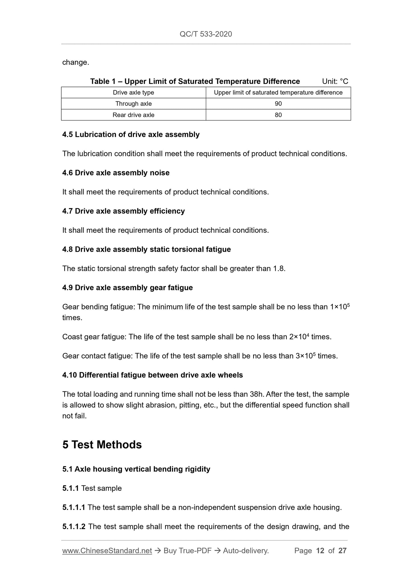
4.4 Drive axle assembly temperature-rise
The upper limit of the saturation temperature difference is shown in Table 1; and the
lubricating oil temperature-time relationship curve shall be smooth without sudden
quantity shall be no less than 1 piece.
5.1.1.3 During the test, the drive axle housing of the full-floating half-shaft structure
shall be equipped with a matching reducer housing, and the rear cover and
accessories (welding accessories of the axle housing, oil drain plug, etc.) shall also be
retained or installed on the axle housing. During the test, the drive axle housing of the
semi-floating half-shaft structure, in addition to installing and retaining the above-
mentioned related parts and accessories, the half-shaft and other components shall
also be installed on the axle housing in accordance with the actual working conditions.
5.1.2 Test equipment and devices
Hydraulic servo test system or other devices capable of applying loads, as well as
deformation measuring devices, force sensors, etc. The error of deformation
measurement shall be within ±0.01mm; the relative error of force measurement shall
be within ±1%.
5.1.3 Test method
5.1.3.1 Install the sample according to the actual load state, the loading position is the
centre of the stress point where the axle housing bears the weight of the vehicle, and
the fulcrum is the corresponding position of the axle housing wheel track.
5.1.3.2 After installation, it shall be ensured that the direction of the applied load is
perpendicular to the centreline of the axle tube of the axle housing; and the degree of
freedom of the fulcrum along the centreline of the axle tube of the axle housing is not
limited; so as to adapt to the test loading deformation without movement interference.
5.1.3.3 After the sample is installed, it is preloaded to the fully loaded axle load for 2~3
times; and then the formal measurement is carried out after unloading.
5.1.3.4 After unloading to zero, adjust the deformation measuring device to the zero
position; and the measuring point position shall be no less than 9 points. The locations
of the measuring points are shown in Figures 1 and 2.
measured at each measuring point, thereof, the maximum value is selected as the final
deformation value of the measuring point.
5.1.4.2 Calculate the ratio of the maximum amount of deformation of the axle housing
(mm) to the wheel track (m) under fully loaded axle load.
5.1.4.3 Draw the deformation amount of each measuring point under the fully loaded
axle load and the specified load (all need to subtract the error value caused by the
fulcrum), and connect them into a line.
5.2 Axle housing vertical bending static strength
5.2.1 Test sample
The same as 5.1.1.
5.2.2 Test equipment and devices
Hydraulic servo test system or other devices capable of applying loads, force sensors,
etc. The relative error of force measurement shall be within ±1%.
5.2.3 Test methods
5.2.3.1 Perform in accordance with 5.1.3.1~5.1.3.3.
5.2.3.2 Continuously and slowly load until the sample is broken, without repeating it in
between. Record the failure (fracture or severe plastic deformation) load.
5.2.4 Data processing
Calculate the axle housing vertical bending static strength safety factor according to
formula (1).
5.3 Axle housing fatigue test
5.3.1 Test sample
The number of fatigue samples for each axle housing shall be no less than 3, and the
other requirements are the same as 5.1.1.
5.3.2 Test equipment and devices
Hydraulic servo test system or other devices capable of applying loads, force sensors,
etc. The relative error of force measurement shall be in the range of ±1%; and the
relative error of force control shall be in the range of ±1%.
5.3.3 Test methods
5.4.2 Test equipment and devices
Oil flow temperature-rise test bench or similar test device, temperature sensor, etc.
The error of speed measurement shall be within the range of ±2r/min; and the error of
temperature measurement shall be within the range of ±0.5°C.
5.4.3 Test methods
5.4.3.1 Add lubricating oil according to the technical requirements of the product.
5.4.3.2 The installation inclination angle of the drive axle is consistent with the no-load
state of the actual vehicle.
5.4.3.3 Install the temperature sensor on the oil drain plug. For wheel-side reduction
drive axles, temperature sensors shall be installed in the left and right wheel-side
reducers at the same time.
5....
Get QUOTATION in 1-minute: Click QC/T 533-2020
Historical versions: QC/T 533-2020
Preview True-PDF (Reload/Scroll if blank)
QC/T 533-2020: Commercial Vehicle Drive Axles Assembly
QC/T 533-2020
QC
NATIONAL STANDARD OF THE
PEOPLE’S REPUBLIC OF CHINA
ICS 43.040.50
T 21
Replacing QC/T 533-1999, QC/T 534-1999
Commercial Vehicle Drive Axles Assembly
ISSUED ON: DECEMBER 09, 2020
IMPLEMENTED ON: APRIL 01, 2021
Issued by: Ministry of Industry and Information Technology of PRC
Table of Contents
Foreword ... 6
1 Scope ... 9
2 Normative References ... 9
3 Terms and Definitions ... 9
4 Technical Requirements ... 11
5 Test Methods ... 12
Commercial Vehicle Drive Axles Assembly
1 Scope
This document specifies the technical requirements and bench test methods for
commercial vehicle drive axle assembly.
This document is applicable to commercial vehicle drive axle assembly, and passenger
vehicle drive axle assembly and electric drive axle assembly can be implemented with
reference to this document.
2 Normative References
The following documents are essential to the application of this document. For the
dated documents, only the versions with the dates indicated are applicable to this
document; for the undated documents, only the latest version (including all the
amendments) is applicable to this document.
QC/T 1126 Automotive Drive Axle Terminology and Definition
3 Terms and Definitions
For the purpose of this document, the following terms and definitions given in QC/T
1126 Automotive Drive Axle Terminology and Definition apply.
3.1 Axle housing vertical bending static strength safety factor
The ratio of the vertical bending failure load to the fully loaded axle load of the axle
housing.
Where:
Kn – vertical bending static strength safety factor;
Pn – vertical bending failure load, in N;
P – fully loaded axle load, in N.
3.7 Saturated temperature difference
The difference between the saturated temperature and the ambient temperature
measured at the corresponding moment.
3.8 Drive axle assembly static torsional strength safety factor
The ratio of the static torsional strength failure torque of the drive axle assembly to the
maximum test torque, Min, of the drive axle assembly.
Where:
Kk – drive axle assembly static torsional strength safety factor;
Mk – drive axle assembly static torsional failure torque, in N • m;
Min – drive axle assembly maximum test torque, in N • m.
4 Technical Requirements
4.1 Axle housing vertical bending rigidity
When fully loaded with axle load, the maximum deformation per meter of wheelbase
shall be no greater than 1.4mm.
4.2 Axle housing vertical bending static strength
Axle housing vertical bending static strength safety factor Kn: tractors shall be greater
than 5, trucks and passenger cars shall be greater than 6.
4.3 Axle housing fatigue
The minimum vertical bending fatigue life: The tractor shall be no less than 8×10⁵ times;
and the truck and passenger car shall be no less than 6×10⁵ times.
The minimum brake fatigue life shall be no less than 8.8×10⁴ cycles.
The minimum lateral bending fatigue life shall be no less than 2×10⁵ times.
4.4 Drive axle assembly temperature-rise
The upper limit of the saturation temperature difference is shown in Table 1; and the
lubricating oil temperature-time relationship curve shall be smooth without sudden
quantity shall be no less than 1 piece.
5.1.1.3 During the test, the drive axle housing of the full-floating half-shaft structure
shall be equipped with a matching reducer housing, and the rear cover and
accessories (welding accessories of the axle housing, oil drain plug, etc.) shall also be
retained or installed on the axle housing. During the test, the drive axle housing of the
semi-floating half-shaft structure, in addition to installing and retaining the above-
mentioned related parts and accessories, the half-shaft and other components shall
also be installed on the axle housing in accordance with the actual working conditions.
5.1.2 Test equipment and devices
Hydraulic servo test system or other devices capable of applying loads, as well as
deformation measuring devices, force sensors, etc. The error of deformation
measurement shall be within ±0.01mm; the relative error of force measurement shall
be within ±1%.
5.1.3 Test method
5.1.3.1 Install the sample according to the actual load state, the loading position is the
centre of the stress point where the axle housing bears the weight of the vehicle, and
the fulcrum is the corresponding position of the axle housing wheel track.
5.1.3.2 After installation, it shall be ensured that the direction of the applied load is
perpendicular to the centreline of the axle tube of the axle housing; and the degree of
freedom of the fulcrum along the centreline of the axle tube of the axle housing is not
limited; so as to adapt to the test loading deformation without movement interference.
5.1.3.3 After the sample is installed, it is preloaded to the fully loaded axle load for 2~3
times; and then the formal measurement is carried out after unloading.
5.1.3.4 After unloading to zero, adjust the deformation measuring device to the zero
position; and the measuring point position shall be no less than 9 points. The locations
of the measuring points are shown in Figures 1 and 2.
measured at each measuring point, thereof, the maximum value is selected as the final
deformation value of the measuring point.
5.1.4.2 Calculate the ratio of the maximum amount of deformation of the axle housing
(mm) to the wheel track (m) under fully loaded axle load.
5.1.4.3 Draw the deformation amount of each measuring point under the fully loaded
axle load and the specified load (all need to subtract the error value caused by the
fulcrum), and connect them into a line.
5.2 Axle housing vertical bending static strength
5.2.1 Test sample
The same as 5.1.1.
5.2.2 Test equipment and devices
Hydraulic servo test system or other devices capable of applying loads, force sensors,
etc. The relative error of force measurement shall be within ±1%.
5.2.3 Test methods
5.2.3.1 Perform in accordance with 5.1.3.1~5.1.3.3.
5.2.3.2 Continuously and slowly load until the sample is broken, without repeating it in
between. Record the failure (fracture or severe plastic deformation) load.
5.2.4 Data processing
Calculate the axle housing vertical bending static strength safety factor according to
formula (1).
5.3 Axle housing fatigue test
5.3.1 Test sample
The number of fatigue samples for each axle housing shall be no less than 3, and the
other requirements are the same as 5.1.1.
5.3.2 Test equipment and devices
Hydraulic servo test system or other devices capable of applying loads, force sensors,
etc. The relative error of force measurement shall be in the range of ±1%; and the
relative error of force control shall be in the range of ±1%.
5.3.3 Test methods
5.4.2 Test equipment and devices
Oil flow temperature-rise test bench or similar test device, temperature sensor, etc.
The error of speed measurement shall be within the range of ±2r/min; and the error of
temperature measurement shall be within the range of ±0.5°C.
5.4.3 Test methods
5.4.3.1 Add lubricating oil according to the technical requirements of the product.
5.4.3.2 The installation inclination angle of the drive axle is consistent with the no-load
state of the actual vehicle.
5.4.3.3 Install the temperature sensor on the oil drain plug. For wheel-side reduction
drive axles, temperature sensors shall be installed in the left and right wheel-side
reducers at the same time.
5....
Share