1
/
of
12
PayPal, credit cards. Download editable-PDF and invoice in 1 second!
GB 44016-2024 English PDF
GB 44016-2024 English PDF
Regular price
$515.00 USD
Regular price
Sale price
$515.00 USD
Unit price
/
per
Shipping calculated at checkout.
Couldn't load pickup availability
Delivery: 3 seconds. Download true-PDF + Invoice.
Get QUOTATION in 1-minute: Click GB 44016-2024
Historical versions: GB 44016-2024
Preview True-PDF (Reload/Scroll if blank)
GB 44016-2024: Electro-magnetic emergency shut-off valve for gas
GB 44016-2024
GB
NATIONAL STANDARD OF THE
PEOPLE’S REPUBLIC OF CHINA
ICS 91.140
CCS P 47
Electro-magnetic Emergency Shut-off Valve for Gas
ISSUED ON. APRIL 29, 2024
IMPLEMENTED ON. AUGUST 1, 2024
Issued by. State Administration for Market Regulation;
Standardization Administration of the People’s Republic of China.
Table of Contents
Foreword... 4
1 Scope... 5
2 Normative References... 5
3 Terms and Definitions... 7
4 Classification and Models... 7
4.1 Classification... 7
4.2 Model... 7
5 Material and Structure... 8
5.1 Material... 8
5.2 Structure... 10
6 Requirements... 13
6.1 General Requirements... 13
6.2 Appearance... 14
6.3 Case... 14
6.4 Strength of Pressure-bearing Parts... 14
6.5 Air Tightness... 14
6.6 Rated Flow... 15
6.7 Emergency Shut-off Performance... 15
6.8 Torque Resistance... 16
6.9 Bending Resistance... 16
6.10 Impact Resistance... 16
6.11 Durability... 17
6.12 Temperature Resistance and Damp Heat Resistance... 17
6.13 Valve Position Status Indication... 17
6.14 Electrical Safety... 17
6.15 Explosion-proof Performance (Ex)... 18
6.16 Protection Performance (IP)... 18
6.17 Properties of Non-metallic Materials... 18
6.18 Corrosion Resistance... 18
6.19 Temperature Rise of Electromagnetic Coil... 18
6.20 Electromagnetic Compatibility Safety... 18
7 Test Methods... 19
7.1 Test Conditions... 19
7.2 Appearance Inspection... 20
7.3 Case Inspection... 20
7.4 Strength Test of Pressure-bearing Parts... 20
7.5 Air Tightness Test... 20
7.6 Rated Flow Test... 21
7.7 Emergency Shut-off Performance Test... 23
7.8 Torque Resistance Test... 24
7.9 Bending Resistance Test... 25
7.10 Impact Resistance Test... 26
7.11 Durability Test... 26
7.12 Temperature Resistance and Damp Heat Resistance Test... 27
7.13 Valve Position Status Indication Test... 27
7.14 Electrical Safety Test... 27
7.15 Explosion-proof Performance Test... 28
7.16 Protection Performance Test... 28
7.17 Non-metallic Material Properties Test... 28
7.18 Corrosion Resistance Test... 28
7.19 Temperature Rise Test of Electromagnetic Coil... 28
7.20 Electromagnetic Compatibility Safety Test... 28
8 Inspection Rules... 29
8.1 Inspection Items... 29
8.2 Exit-factory Inspection... 29
8.3 Type Inspection... 29
9 Marking and Instructions for Use... 30
9.1 Marking... 30
9.2 Instructions for Use... 31
10 Packaging, Transportation and Storage... 31
10.1 Packaging... 31
10.2 Transportation... 32
10.3 Storage... 32
Electro-magnetic Emergency Shut-off Valve for Gas
1 Scope
This document defines the terms and definitions of electro-magnetic emergency shut-off valve
for gas; specifies the classification and model, material and structure, and requirements;
describes corresponding test methods; clarifies the inspection rules, and the requirements for
marking and instructions for use, packaging, transportation, and storage, etc.
This document is applicable to electro-magnetic emergency shut-off valves for gas installed on
gas user pipelines where the maximum working pressure is not greater than 0.4 MPa and the
nominal dimension is not greater than DN300, and the transmission media are natural gas,
liquefied petroleum gas (including liquefied petroleum gas mixed with air) and artificial gas
(hereinafter referred to as the “shut-off valves”).
2 Normative References
The contents of the following documents constitute indispensable clauses of this document
through the normative references in the text. In terms of references with a specified date, only
versions with a specified date are applicable to this document. In terms of references without a
specified date, the latest version (including all the modifications) is applicable to this document.
GB/T 229 Metallic Materials - Charpy Pendulum Impact Test Method
GB/T 699 Quality Carbon Structure Steels
GB/T 700 Carbon Structural Steels
GB/T 1173 Casting Aluminum Alloy
GB/T 1220 Stainless Steel Bars
GB/T 1239.2 Cold Coiled Helical Springs Technical Specifications - Part 2.Compressions
Spring
GB/T 1348 Spheroidal Graphite Iron Castings
GB/T 1591 High-strength Low-alloy Structural Steel
GB/T 1690-2010 Rubber, Vulcanized or Thermoplastic - Determination of the Effect of Liquids
GB/T 3191 Extrusion Rods and Bars of Aluminum and Aluminum Alloys
GB(/T) 3836 (all parts) Explosive Atmospheres
GB/T 4208 Degrees of Protection Provided by Enclosure (IP code)
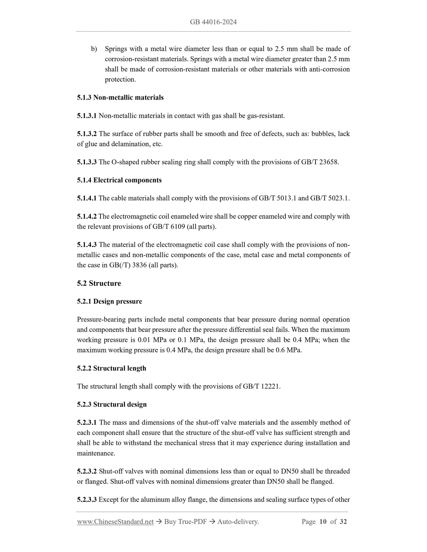
b) Springs with a metal wire diameter less than or equal to 2.5 mm shall be made of
corrosion-resistant materials. Springs with a metal wire diameter greater than 2.5 mm
shall be made of corrosion-resistant materials or other materials with anti-corrosion
protection.
5.1.3 Non-metallic materials
5.1.3.1 Non-metallic materials in contact with gas shall be gas-resistant.
5.1.3.2 The surface of rubber parts shall be smooth and free of defects, such as. bubbles, lack
of glue and delamination, etc.
5.1.3.3 The O-shaped rubber sealing ring shall comply with the provisions of GB/T 23658.
5.1.4 Electrical components
5.1.4.1 The cable materials shall comply with the provisions of GB/T 5013.1 and GB/T 5023.1.
5.1.4.2 The electromagnetic coil enameled wire shall be copper enameled wire and comply with
the relevant provisions of GB/T 6109 (all parts).
5.1.4.3 The material of the electromagnetic coil case shall comply with the provisions of non-
metallic cases and non-metallic components of the case, metal case and metal components of
the case in GB(/T) 3836 (all parts).
5.2 Structure
5.2.1 Design pressure
Pressure-bearing parts include metal components that bear pressure during normal operation
and components that bear pressure after the pressure differential seal fails. When the maximum
working pressure is 0.01 MPa or 0.1 MPa, the design pressure shall be 0.4 MPa; when the
maximum working pressure is 0.4 MPa, the design pressure shall be 0.6 MPa.
5.2.2 Structural length
The structural length shall comply with the provisions of GB/T 12221.
5.2.3 Structural design
5.2.3.1 The mass and dimensions of the shut-off valve materials and the assembly method of
each component shall ensure that the structure of the shut-off valve has sufficient strength and
shall be able to withstand the mechanical stress that it may experience during installation and
maintenance.
5.2.3.2 Shut-off valves with nominal dimensions less than or equal to DN50 shall be threaded
or flanged. Shut-off valves with nominal dimensions greater than DN50 shall be flanged.
5.2.3.3 Except for the aluminum alloy flange, the dimensions and sealing surface types of other
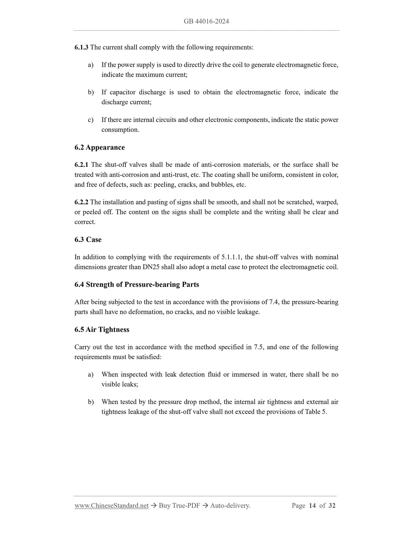
6.1.3 The current shall comply with the following requirements.
a) If the power supply is used to directly drive the coil to generate electromagnetic force,
indicate the maximum current;
b) If capacitor discharge is used to obtain the electromagnetic force, indicate the
discharge current;
c) If there are internal circuits and other electronic components, indicate the static power
consumption.
6.2 Appearance
6.2.1 The shut-off valves shall be made of anti-corrosion materials, or the surface shall be
treated with anti-corrosion and anti-trust, etc. The coating shall be uniform, consistent in color,
and free of defects, such as. peeling, cracks, and bubbles...
Get QUOTATION in 1-minute: Click GB 44016-2024
Historical versions: GB 44016-2024
Preview True-PDF (Reload/Scroll if blank)
GB 44016-2024: Electro-magnetic emergency shut-off valve for gas
GB 44016-2024
GB
NATIONAL STANDARD OF THE
PEOPLE’S REPUBLIC OF CHINA
ICS 91.140
CCS P 47
Electro-magnetic Emergency Shut-off Valve for Gas
ISSUED ON. APRIL 29, 2024
IMPLEMENTED ON. AUGUST 1, 2024
Issued by. State Administration for Market Regulation;
Standardization Administration of the People’s Republic of China.
Table of Contents
Foreword... 4
1 Scope... 5
2 Normative References... 5
3 Terms and Definitions... 7
4 Classification and Models... 7
4.1 Classification... 7
4.2 Model... 7
5 Material and Structure... 8
5.1 Material... 8
5.2 Structure... 10
6 Requirements... 13
6.1 General Requirements... 13
6.2 Appearance... 14
6.3 Case... 14
6.4 Strength of Pressure-bearing Parts... 14
6.5 Air Tightness... 14
6.6 Rated Flow... 15
6.7 Emergency Shut-off Performance... 15
6.8 Torque Resistance... 16
6.9 Bending Resistance... 16
6.10 Impact Resistance... 16
6.11 Durability... 17
6.12 Temperature Resistance and Damp Heat Resistance... 17
6.13 Valve Position Status Indication... 17
6.14 Electrical Safety... 17
6.15 Explosion-proof Performance (Ex)... 18
6.16 Protection Performance (IP)... 18
6.17 Properties of Non-metallic Materials... 18
6.18 Corrosion Resistance... 18
6.19 Temperature Rise of Electromagnetic Coil... 18
6.20 Electromagnetic Compatibility Safety... 18
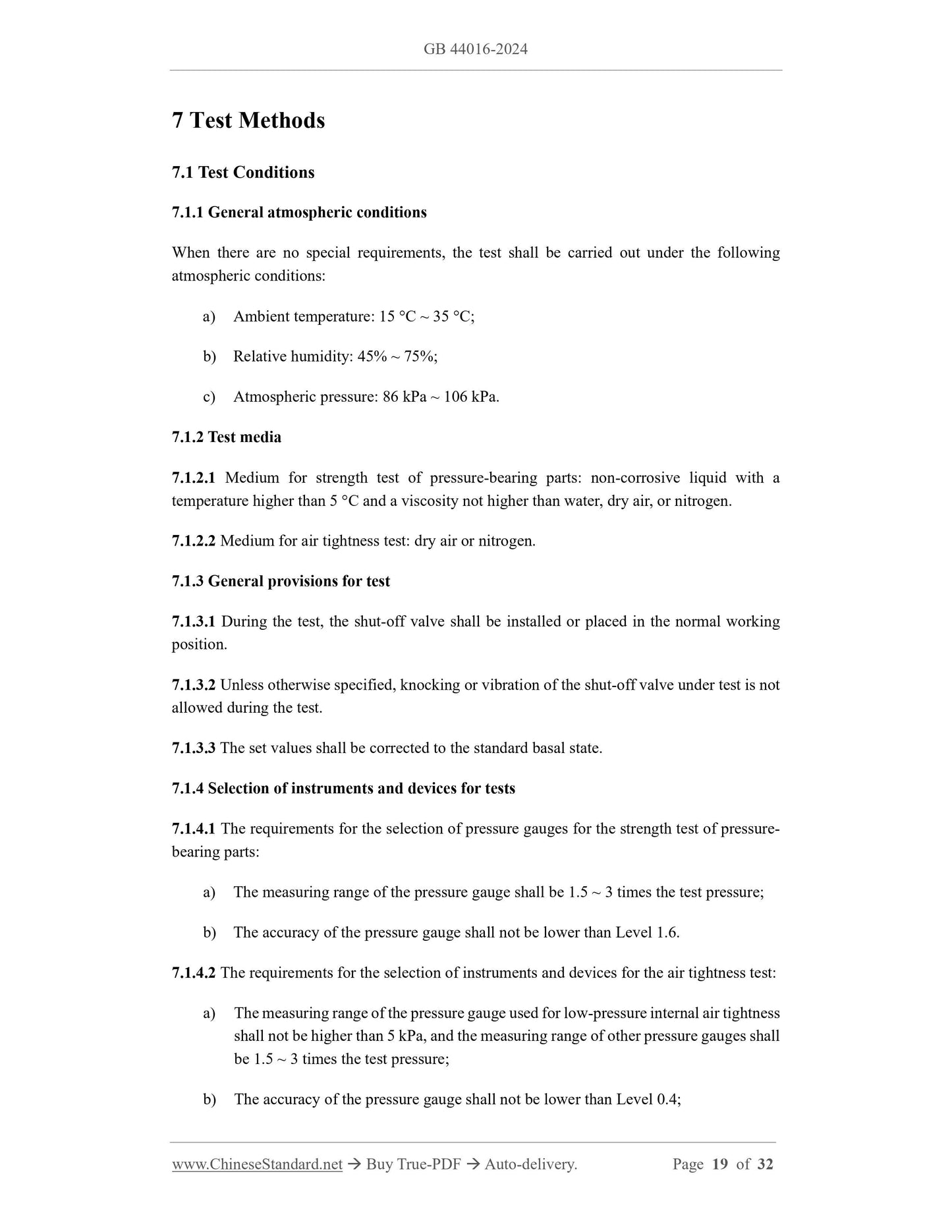
7 Test Methods... 19
7.1 Test Conditions... 19
7.2 Appearance Inspection... 20
7.3 Case Inspection... 20
7.4 Strength Test of Pressure-bearing Parts... 20
7.5 Air Tightness Test... 20
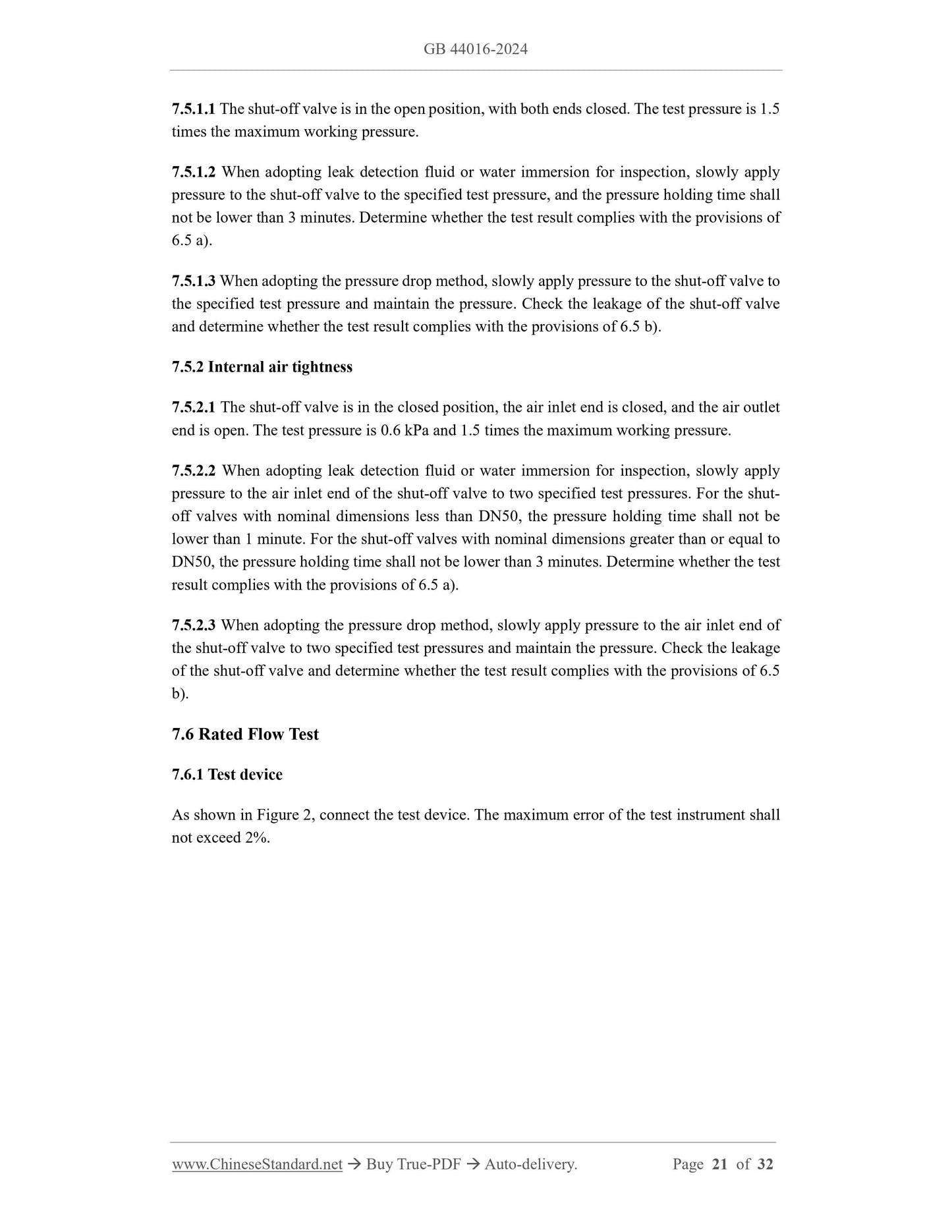
7.6 Rated Flow Test... 21
7.7 Emergency Shut-off Performance Test... 23
7.8 Torque Resistance Test... 24
7.9 Bending Resistance Test... 25
7.10 Impact Resistance Test... 26
7.11 Durability Test... 26
7.12 Temperature Resistance and Damp Heat Resistance Test... 27
7.13 Valve Position Status Indication Test... 27
7.14 Electrical Safety Test... 27
7.15 Explosion-proof Performance Test... 28
7.16 Protection Performance Test... 28
7.17 Non-metallic Material Properties Test... 28
7.18 Corrosion Resistance Test... 28
7.19 Temperature Rise Test of Electromagnetic Coil... 28
7.20 Electromagnetic Compatibility Safety Test... 28
8 Inspection Rules... 29
8.1 Inspection Items... 29
8.2 Exit-factory Inspection... 29
8.3 Type Inspection... 29
9 Marking and Instructions for Use... 30
9.1 Marking... 30
9.2 Instructions for Use... 31
10 Packaging, Transportation and Storage... 31
10.1 Packaging... 31
10.2 Transportation... 32
10.3 Storage... 32
Electro-magnetic Emergency Shut-off Valve for Gas
1 Scope
This document defines the terms and definitions of electro-magnetic emergency shut-off valve
for gas; specifies the classification and model, material and structure, and requirements;
describes corresponding test methods; clarifies the inspection rules, and the requirements for
marking and instructions for use, packaging, transportation, and storage, etc.
This document is applicable to electro-magnetic emergency shut-off valves for gas installed on
gas user pipelines where the maximum working pressure is not greater than 0.4 MPa and the
nominal dimension is not greater than DN300, and the transmission media are natural gas,
liquefied petroleum gas (including liquefied petroleum gas mixed with air) and artificial gas
(hereinafter referred to as the “shut-off valves”).
2 Normative References
The contents of the following documents constitute indispensable clauses of this document
through the normative references in the text. In terms of references with a specified date, only
versions with a specified date are applicable to this document. In terms of references without a
specified date, the latest version (including all the modifications) is applicable to this document.
GB/T 229 Metallic Materials - Charpy Pendulum Impact Test Method
GB/T 699 Quality Carbon Structure Steels
GB/T 700 Carbon Structural Steels
GB/T 1173 Casting Aluminum Alloy
GB/T 1220 Stainless Steel Bars
GB/T 1239.2 Cold Coiled Helical Springs Technical Specifications - Part 2.Compressions
Spring
GB/T 1348 Spheroidal Graphite Iron Castings
GB/T 1591 High-strength Low-alloy Structural Steel
GB/T 1690-2010 Rubber, Vulcanized or Thermoplastic - Determination of the Effect of Liquids
GB/T 3191 Extrusion Rods and Bars of Aluminum and Aluminum Alloys
GB(/T) 3836 (all parts) Explosive Atmospheres
GB/T 4208 Degrees of Protection Provided by Enclosure (IP code)
b) Springs with a metal wire diameter less than or equal to 2.5 mm shall be made of
corrosion-resistant materials. Springs with a metal wire diameter greater than 2.5 mm
shall be made of corrosion-resistant materials or other materials with anti-corrosion
protection.
5.1.3 Non-metallic materials
5.1.3.1 Non-metallic materials in contact with gas shall be gas-resistant.
5.1.3.2 The surface of rubber parts shall be smooth and free of defects, such as. bubbles, lack
of glue and delamination, etc.
5.1.3.3 The O-shaped rubber sealing ring shall comply with the provisions of GB/T 23658.
5.1.4 Electrical components
5.1.4.1 The cable materials shall comply with the provisions of GB/T 5013.1 and GB/T 5023.1.
5.1.4.2 The electromagnetic coil enameled wire shall be copper enameled wire and comply with
the relevant provisions of GB/T 6109 (all parts).
5.1.4.3 The material of the electromagnetic coil case shall comply with the provisions of non-
metallic cases and non-metallic components of the case, metal case and metal components of
the case in GB(/T) 3836 (all parts).
5.2 Structure
5.2.1 Design pressure
Pressure-bearing parts include metal components that bear pressure during normal operation
and components that bear pressure after the pressure differential seal fails. When the maximum
working pressure is 0.01 MPa or 0.1 MPa, the design pressure shall be 0.4 MPa; when the
maximum working pressure is 0.4 MPa, the design pressure shall be 0.6 MPa.
5.2.2 Structural length
The structural length shall comply with the provisions of GB/T 12221.
5.2.3 Structural design
5.2.3.1 The mass and dimensions of the shut-off valve materials and the assembly method of
each component shall ensure that the structure of the shut-off valve has sufficient strength and
shall be able to withstand the mechanical stress that it may experience during installation and
maintenance.
5.2.3.2 Shut-off valves with nominal dimensions less than or equal to DN50 shall be threaded
or flanged. Shut-off valves with nominal dimensions greater than DN50 shall be flanged.
5.2.3.3 Except for the aluminum alloy flange, the dimensions and sealing surface types of other
6.1.3 The current shall comply with the following requirements.
a) If the power supply is used to directly drive the coil to generate electromagnetic force,
indicate the maximum current;
b) If capacitor discharge is used to obtain the electromagnetic force, indicate the
discharge current;
c) If there are internal circuits and other electronic components, indicate the static power
consumption.
6.2 Appearance
6.2.1 The shut-off valves shall be made of anti-corrosion materials, or the surface shall be
treated with anti-corrosion and anti-trust, etc. The coating shall be uniform, consistent in color,
and free of defects, such as. peeling, cracks, and bubbles...
Share