1
/
of
12
www.ChineseStandard.us -- Field Test Asia Pte. Ltd.
GB 50017-2017 English PDF
GB 50017-2017 English PDF
Regular price
$495.00
Regular price
Sale price
$495.00
Unit price
/
per
Shipping calculated at checkout.
Couldn't load pickup availability
GB 50017-2017: Standard for design of steel structures
Delivery: 9 seconds. Download (& Email) true-PDF + Invoice.
Get Quotation: Click GB 50017-2017 (Self-service in 1-minute)
Historical versions (Master-website): GB 50017-2017
Preview True-PDF (Reload/Scroll-down if blank)
GB 50017-2017
GB
NATIONAL STANDARD OF THE
PEOPLE’S REPUBLIC OF CHINA
UDC
P GB 50017-2017
Standard for design of steel structures
ISSUED ON. DECEMBER 12, 2017
IMPLEMENTED ON. JULY 01, 2018
Issued by. Ministry of Housing and Urban-Rural Development of PRC;
General Administration of Quality Supervision Inspection and
Quarantine of PRC.
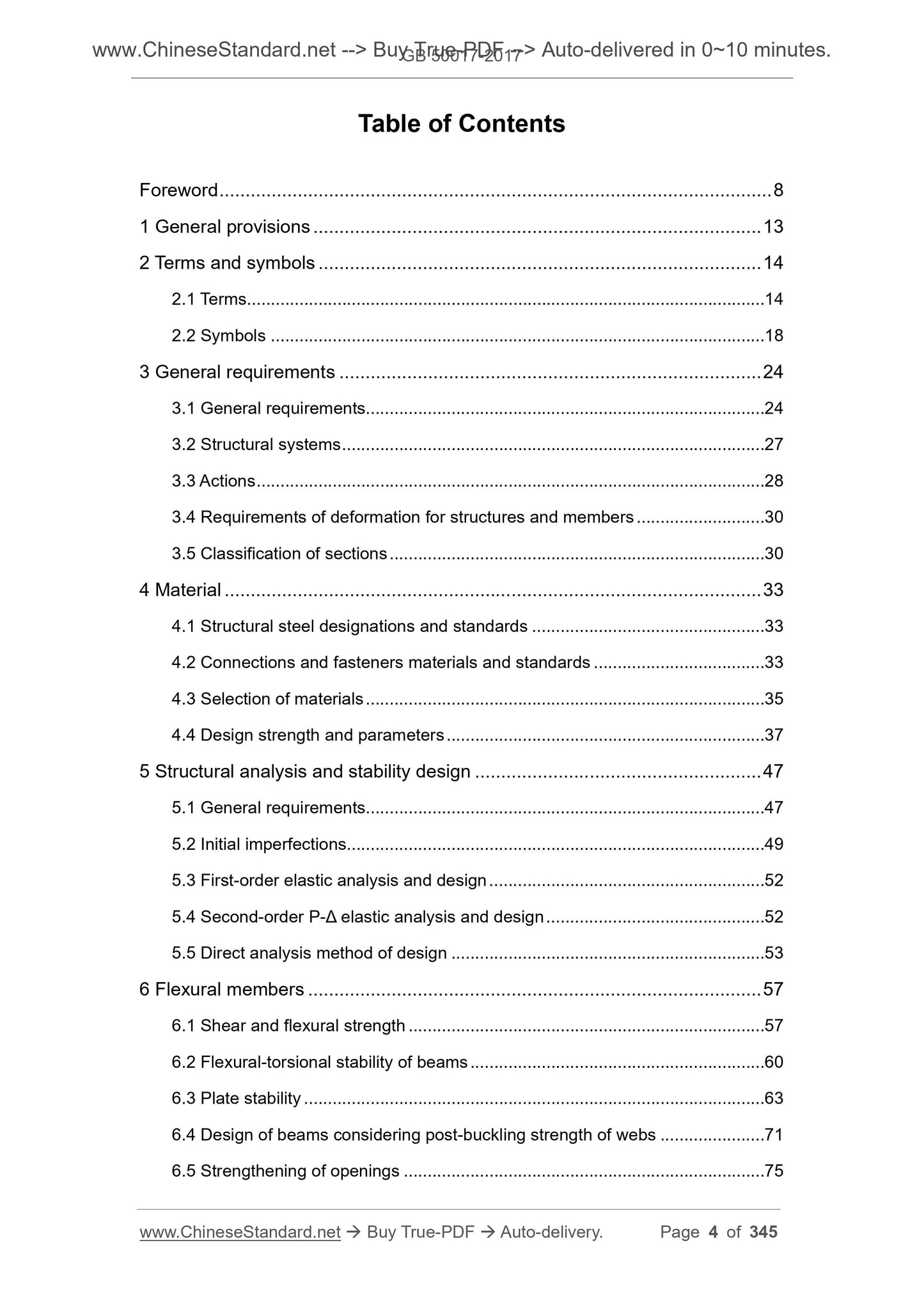
Table of Contents
Foreword ... 8
1 General provisions ... 13
2 Terms and symbols ... 14
2.1 Terms ... 14
2.2 Symbols ... 18
3 General requirements ... 24
3.1 General requirements... 24
3.2 Structural systems ... 27
3.3 Actions ... 28
3.4 Requirements of deformation for structures and members ... 30
3.5 Classification of sections ... 30
4 Material ... 33
4.1 Structural steel designations and standards ... 33
4.2 Connections and fasteners materials and standards ... 33
4.3 Selection of materials ... 35
4.4 Design strength and parameters ... 37
5 Structural analysis and stability design ... 47
5.1 General requirements... 47
5.2 Initial imperfections... 49
5.3 First-order elastic analysis and design ... 52
5.4 Second-order P-Δ elastic analysis and design ... 52
5.5 Direct analysis method of design ... 53
6 Flexural members ... 57
6.1 Shear and flexural strength ... 57
6.2 Flexural-torsional stability of beams ... 60
6.3 Plate stability ... 63
6.4 Design of beams considering post-buckling strength of webs ... 71
6.5 Strengthening of openings ... 75
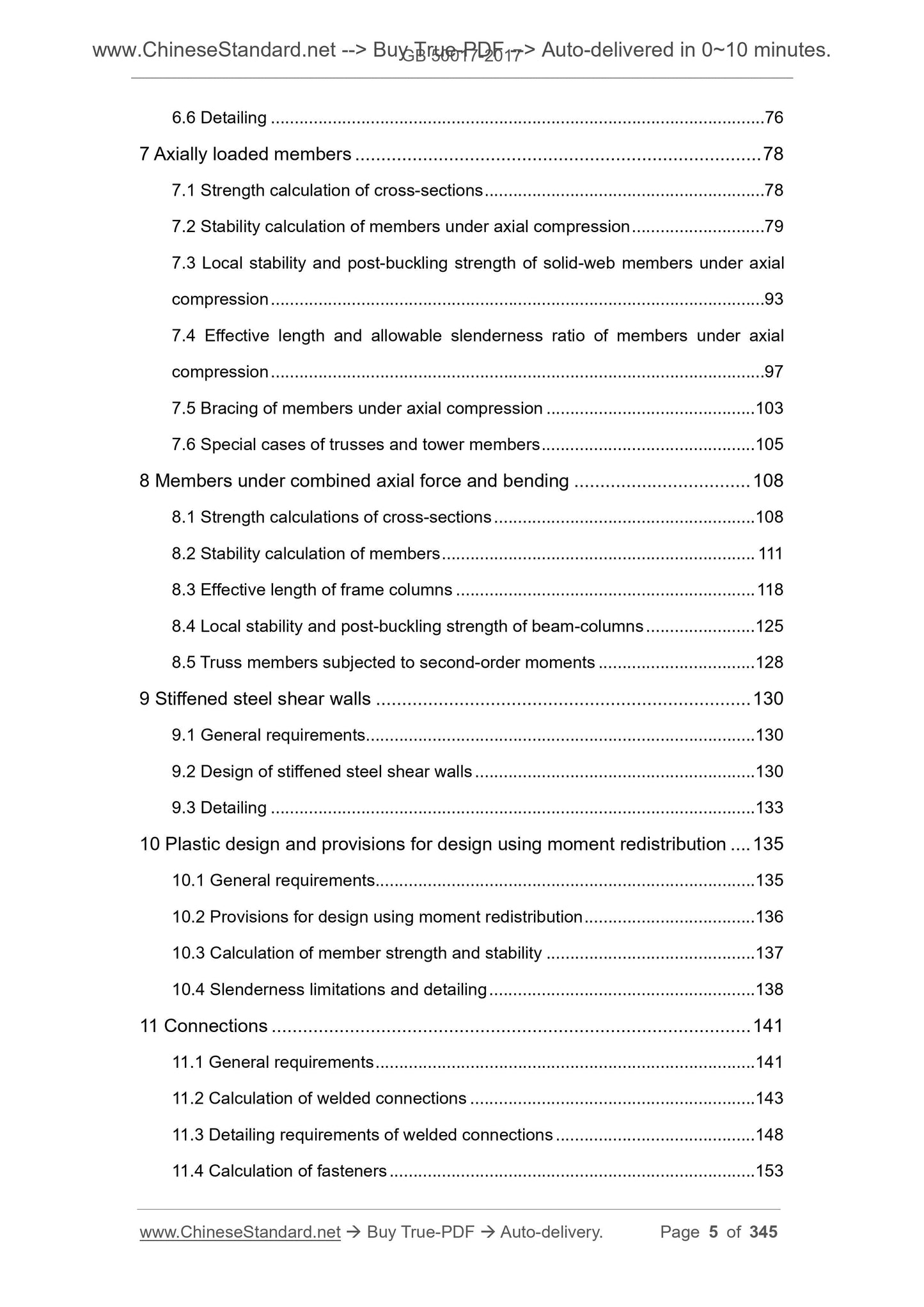
6.6 Detailing ... 76
7 Axially loaded members ... 78
7.1 Strength calculation of cross-sections ... 78
7.2 Stability calculation of members under axial compression ... 79
7.3 Local stability and post-buckling strength of solid-web members under axial
compression ... 93
7.4 Effective length and allowable slenderness ratio of members under axial
compression ... 97
7.5 Bracing of members under axial compression ... 103
7.6 Special cases of trusses and tower members ... 105
8 Members under combined axial force and bending ... 108
8.1 Strength calculations of cross-sections ... 108
8.2 Stability calculation of members ... 111
8.3 Effective length of frame columns ... 118
8.4 Local stability and post-buckling strength of beam-columns ... 125
8.5 Truss members subjected to second-order moments ... 128
9 Stiffened steel shear walls ... 130
9.1 General requirements... 130
9.2 Design of stiffened steel shear walls ... 130
9.3 Detailing ... 133
10 Plastic design and provisions for design using moment redistribution ... 135
10.1 General requirements... 135
10.2 Provisions for design using moment redistribution ... 136
10.3 Calculation of member strength and stability ... 137
10.4 Slenderness limitations and detailing ... 138
11 Connections ... 141
11.1 General requirements ... 141
11.2 Calculation of welded connections ... 143
11.3 Detailing requirements of welded connections ... 148
11.4 Calculation of fasteners ... 153
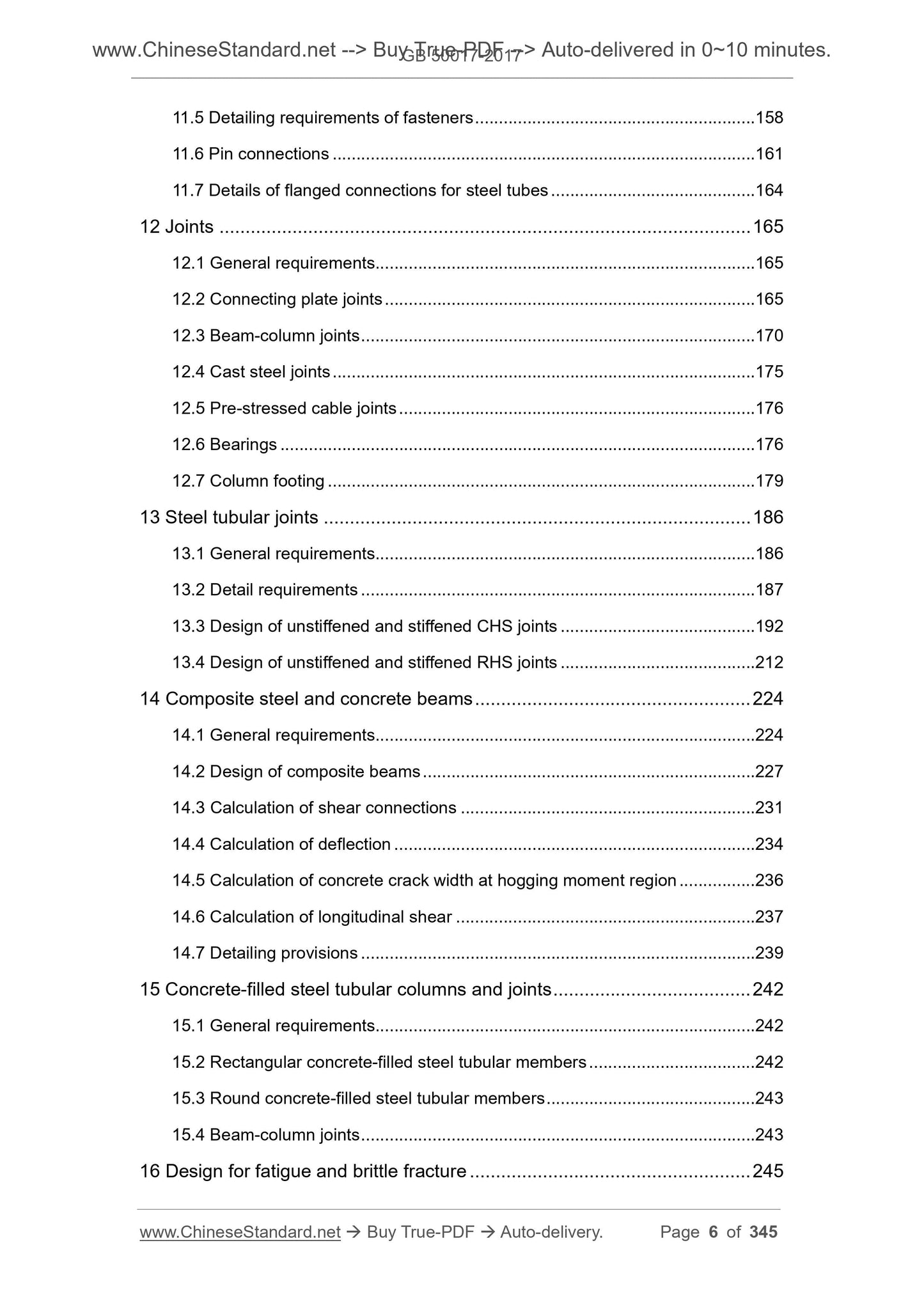
11.5 Detailing requirements of fasteners ... 158
11.6 Pin connections ... 161
11.7 Details of flanged connections for steel tubes ... 164
12 Joints ... 165
12.1 General requirements... 165
12.2 Connecting plate joints ... 165
12.3 Beam-column joints ... 170
12.4 Cast steel joints ... 175
12.5 Pre-stressed cable joints ... 176
12.6 Bearings ... 176
12.7 Column footing ... 179
13 Steel tubular joints ... 186
13.1 General requirements... 186
13.2 Detail requirements ... 187
13.3 Design of unstiffened and stiffened CHS joints ... 192
13.4 Design of unstiffened and stiffened RHS joints ... 212
14 Composite steel and concrete beams ... 224
14.1 General requirements... 224
14.2 Design of composite beams ... 227
14.3 Calculation of shear connections ... 231
14.4 Calculation of deflection ... 234
14.5 Calculation of concrete crack width at hogging moment region ... 236
14.6 Calculation of longitudinal shear ... 237
14.7 Detailing provisions ... 239
15 Concrete-filled steel tubular columns and joints ... 242
15.1 General requirements... 242
15.2 Rectangular concrete-filled steel tubular members ... 242
15.3 Round concrete-filled steel tubular members ... 243
15.4 Beam-column joints ... 243
16 Design for fatigue and brittle fracture ... 245
16.1 General requirements... 245
16.2 Design for fatigue ... 245
16.3 Detailing requirements ... 252
16.4 Prevention of brittle fracture ... 256
17 Seismic design of steel structural members ... 258
17.1 General requirements... 258
17.2 Design requirements ... 262
17.3 Connections and details ... 277
18 Protection of steel structures ... 286
18.1 Fire-resistance design ... 286
18.2 Corrosion prevention design ... 286
18.3 Temperature insulation ... 289
Appendix A Common structural systems ... 290
Appendix B Limits of deflection for structures and flexural members ... 293
Appendix C Overall stability of beams ... 298
Appendix D Stability coefficients of members under axial compression ... 304
Appendix E Effective length factors of columns ... 309
Appendix F Elastic buckling stresses for stiffened steel shear walls ... 318
Appendix G Buckling calculation of truss connecting plate under diagonal
compression... 327
Appendix H Classifications of unstiffened tubular joints in terms of rigidity 329
Appendix J Fatigue design of composite steel and concrete beams ... 332
Appendix K Design values for compressive and shear strength of composite
round concrete-filled steel tubes ... 334
Explanation of wording in this standard ... 343
List of quoted standards ... 344
Standard for design of steel structures
1 General provisions
1.0.1 To implement the national technical and economic policies in the design
of steel structures, to achieve advanced technology, safety and application,
economic rationality, and quality assurance, this standard is hereby formulated.
1.0.2 This standard applies to the design of steel structures for industrial and civil
buildings as well as general structures.
1.0.3 In addition to complying with this standard, the design of steel structure
shall also comply with the provisions of relevant national standards.
2 Terms and symbols
2.1 Terms
2.1.1 Brittle fracture
The sudden fracture of structure or member which does not exhibit a plastic
deformation of alarming nature under the tensile stress.
2.1.2 First-order elastic analysis
The establishment of balancing conditions in accordance with the undeformed
structure as well as the analysis of structure’s internal force and displacement
by elastic phases, which does not consider the impacts of the geometric
nonlinearity on the structure’s internal force and deformation.
2.1.3 Second-order P-Δ elastic analysis
The establishment of balancing conditions in accordance with the displaced
structure as well as the analysis of structure’s internal force and displacement
by elastic phases, which only considers the impacts of the initial overall defect
of the structure and the geometric nonlinearity on the structure’s internal force
and deformation.
2.1.4 direct analysis method of design
The design method of using the overall structural system as an object to
perform the second-order nonlinear analysis, which directly considers the
factors of initial geometric defects, residual stress, material nonlinearity, joint
stiffness and so on that have significant influence on structural stability and
strength performance.
2.1.5 Buckling
Another state of significant deformation of the structure, member or steel plate
along the direction of weaker stiffness which reaches the critical state of bearing.
2.1.6 Post-buckling strength of steel plate
The capability of steel plate to continuously withstand larger load after it is
buckled.
2.1.7 Normalized slenderness ratio
A parameter, of which the value is equal to the square root of the quotient of the
bending, shearing or compressive yield strength of the steel AND the
corresponding flexural, shear or compressive elastic buckling stress of the
member or steel plate.
2.1.8 Overall stability
The capability of a member or structure to remain stable as a whole under load.
2.1.9 Effective width
When calculating the post-buckling ultimate strength of the steel plate, the
resulting reduced width which is obtained by using the uniformly distributed
yield strength to equivalent the width of the steel plate which is subject to the
non-uniformly distributed ultimate stress.
2.1.10 Effective width factor
The ratio of the effective width to the actual width of the steel plate.
2.1.11 Effective length ratio
Coefficients associated with the buckling mode of the member and the
rotational constraints at both ends.
2.1.12 Effective length
The length used to calculate stability, the value of which is equal to the product
of the geometric length of the member between its effective constraint points
and the effective length ratio.
2.1.13 Slenderness ratio
The ratio of the effective length of the member to the turning radius of the
member section.
2.1.14 Equivalent slenderness ratio
In the overall stability calculation of the axially loaded members, in accordance
with the principles of equal critical force, the slenderness ratio corresponding to
the calculation which converts the lattice members to solid-web members, or
the calculation which converts the bending torsional and torsional instability into
bending instability calculations.
2.1.15 Nodal bracing force
The lateral force which is used for bracing along the buckling direction of the
braced members (or the compressed flange of the member), at the lateral
support which is provided to reduce the free length of the compressed member
(or the compressed flange of the member).
2.1.16 Unbraced frame
The structure which uses the bending resistance of the joint and the member to
resist the load.
2.1.17 Bracing structure
In the plane in which the beam-column members are located, the structure
which has the obliquely-arranged bracing member to support the axial stiffness
and to resist the lateral load.
2.1.18 Frame-bracing structure
The structure of the anti-lateral force system which is composed of a frame and
a bracing.
2.1.19 Frame braced with strong bracing system
In the frame-bracing structure, if the bracing structure (bracing truss, shear wall,
cylinder, etc.) has a large lateral stiffness resistance, the frame can be regarded
as a frame without lateral displacement.
2.1.20 Leaning column
The column which is designed only to by axially loaded but does not consider
the lateral stiffness.
2.1.21 Panel zone
The region of the rigid joints of the frame beam-column and the column webs
which are provided with stiffeners or partitions on the upper and lower sides of
the beam height range.
2.1.22 Spherical steel bearing
The hinged bearing or movable bearing the steel spherical surface of which can
be rotated in any direction at the bearing.
2.1.23 Steel-plate shear wall
A steel plate which is placed between the frame beam-column to withstand the
horizontal shear in the frame.
2.1.24 Chord member
In a steel tubular structure member, a tube member which is continuously cut
through at the joint, such as a chord in a truss.
2.1.25 Branch member
In a steel tubular structure, a tube member that is disconnected at a joint and
connected to a chord member, such as a web member in a truss to connect to
a chord member.
2.1.26 Gap joint
A tube joint the two branch members of which depart for a certain distance.
2.1.27 Overlap joint
At the steel-tube joint, the joint where the two branch members overlap each
other.
2.1.28 Uniplanar joint
A joint in which the branch member and the chord member are connected to
each other in the same plane.
2.1.29 Multiplanar joint
A tube joint formed by connecting a plurality of branch members in different
planes to a chord member.
2.1.30 Welded section
A section made of a steel plate (or profile steel) through welding.
2.1.31 Composite steel and concrete beam
A beam which is formed by the concrete flange and steel beam through the
shear connections and can be integrally loaded.
2.1.32 Bracing system
An anti-lateral force system which consists of beams (including foundation
beams) and columns that support and transmit their internal forces.
2.1.33 Link
In an eccentric bracing frame structure, a beam section which is located
between the two oblique bracing ends or a beam section which is located
between an oblique bracing end and the column.
2.1.34 Concentrically braced frame
A frame whose oblique bracing intersects with the frame beam-column at one
point.
2.1.35 Eccentrically braced frame
4 Material
4.1 Structural steel designations and standards
4.1.1 Steels should be Q235, Q345, Q390, Q420, Q460 and Q345GJ steels.
The quality shall comply with the provisions of the current national standards
“Carbon structural steels” GB/T 700, “High strength low alloy structural steels”
GB/T 1591, and “Steel plates for building structure” GB/T 19879. The
specifications, shape, weight and allowable deviation of steel plates, hot-rolled
I-beams, channel steels, angle-steels, H-shape profile steels, steel-tubes, and
other profiles for structural use shall comply with the provisions of relevant
national standards.
4.1.2 When the welded load-bearing structure uses the Z-direction steel to
prevent laminar tearing of steel, the quality shall comply with the current
national standard “Steel plates with through-thickness characteristics” GB/T
5313.
4.1.3 For load-bearing structures that are exposed in open-air and have special
requirements for corrosion resistance or are in an aggressive medium
environment, it may use the weather-proof structural steel of designation
Q235NH, Q355NH and Q415NH, the quality of which shall comply with the
current n...
Delivery: 9 seconds. Download (& Email) true-PDF + Invoice.
Get Quotation: Click GB 50017-2017 (Self-service in 1-minute)
Historical versions (Master-website): GB 50017-2017
Preview True-PDF (Reload/Scroll-down if blank)
GB 50017-2017
GB
NATIONAL STANDARD OF THE
PEOPLE’S REPUBLIC OF CHINA
UDC
P GB 50017-2017
Standard for design of steel structures
ISSUED ON. DECEMBER 12, 2017
IMPLEMENTED ON. JULY 01, 2018
Issued by. Ministry of Housing and Urban-Rural Development of PRC;
General Administration of Quality Supervision Inspection and
Quarantine of PRC.
Table of Contents
Foreword ... 8
1 General provisions ... 13
2 Terms and symbols ... 14
2.1 Terms ... 14
2.2 Symbols ... 18
3 General requirements ... 24
3.1 General requirements... 24
3.2 Structural systems ... 27
3.3 Actions ... 28
3.4 Requirements of deformation for structures and members ... 30
3.5 Classification of sections ... 30
4 Material ... 33
4.1 Structural steel designations and standards ... 33
4.2 Connections and fasteners materials and standards ... 33
4.3 Selection of materials ... 35
4.4 Design strength and parameters ... 37
5 Structural analysis and stability design ... 47
5.1 General requirements... 47
5.2 Initial imperfections... 49
5.3 First-order elastic analysis and design ... 52
5.4 Second-order P-Δ elastic analysis and design ... 52
5.5 Direct analysis method of design ... 53
6 Flexural members ... 57
6.1 Shear and flexural strength ... 57
6.2 Flexural-torsional stability of beams ... 60
6.3 Plate stability ... 63
6.4 Design of beams considering post-buckling strength of webs ... 71
6.5 Strengthening of openings ... 75
6.6 Detailing ... 76
7 Axially loaded members ... 78
7.1 Strength calculation of cross-sections ... 78
7.2 Stability calculation of members under axial compression ... 79
7.3 Local stability and post-buckling strength of solid-web members under axial
compression ... 93
7.4 Effective length and allowable slenderness ratio of members under axial
compression ... 97
7.5 Bracing of members under axial compression ... 103
7.6 Special cases of trusses and tower members ... 105
8 Members under combined axial force and bending ... 108
8.1 Strength calculations of cross-sections ... 108
8.2 Stability calculation of members ... 111
8.3 Effective length of frame columns ... 118
8.4 Local stability and post-buckling strength of beam-columns ... 125
8.5 Truss members subjected to second-order moments ... 128
9 Stiffened steel shear walls ... 130
9.1 General requirements... 130
9.2 Design of stiffened steel shear walls ... 130
9.3 Detailing ... 133
10 Plastic design and provisions for design using moment redistribution ... 135
10.1 General requirements... 135
10.2 Provisions for design using moment redistribution ... 136
10.3 Calculation of member strength and stability ... 137
10.4 Slenderness limitations and detailing ... 138
11 Connections ... 141
11.1 General requirements ... 141
11.2 Calculation of welded connections ... 143
11.3 Detailing requirements of welded connections ... 148
11.4 Calculation of fasteners ... 153
11.5 Detailing requirements of fasteners ... 158
11.6 Pin connections ... 161
11.7 Details of flanged connections for steel tubes ... 164
12 Joints ... 165
12.1 General requirements... 165
12.2 Connecting plate joints ... 165
12.3 Beam-column joints ... 170
12.4 Cast steel joints ... 175
12.5 Pre-stressed cable joints ... 176
12.6 Bearings ... 176
12.7 Column footing ... 179
13 Steel tubular joints ... 186
13.1 General requirements... 186
13.2 Detail requirements ... 187
13.3 Design of unstiffened and stiffened CHS joints ... 192
13.4 Design of unstiffened and stiffened RHS joints ... 212
14 Composite steel and concrete beams ... 224
14.1 General requirements... 224
14.2 Design of composite beams ... 227
14.3 Calculation of shear connections ... 231
14.4 Calculation of deflection ... 234
14.5 Calculation of concrete crack width at hogging moment region ... 236
14.6 Calculation of longitudinal shear ... 237
14.7 Detailing provisions ... 239
15 Concrete-filled steel tubular columns and joints ... 242
15.1 General requirements... 242
15.2 Rectangular concrete-filled steel tubular members ... 242
15.3 Round concrete-filled steel tubular members ... 243
15.4 Beam-column joints ... 243
16 Design for fatigue and brittle fracture ... 245
16.1 General requirements... 245
16.2 Design for fatigue ... 245
16.3 Detailing requirements ... 252
16.4 Prevention of brittle fracture ... 256
17 Seismic design of steel structural members ... 258
17.1 General requirements... 258
17.2 Design requirements ... 262
17.3 Connections and details ... 277
18 Protection of steel structures ... 286
18.1 Fire-resistance design ... 286
18.2 Corrosion prevention design ... 286
18.3 Temperature insulation ... 289
Appendix A Common structural systems ... 290
Appendix B Limits of deflection for structures and flexural members ... 293
Appendix C Overall stability of beams ... 298
Appendix D Stability coefficients of members under axial compression ... 304
Appendix E Effective length factors of columns ... 309
Appendix F Elastic buckling stresses for stiffened steel shear walls ... 318
Appendix G Buckling calculation of truss connecting plate under diagonal
compression... 327
Appendix H Classifications of unstiffened tubular joints in terms of rigidity 329
Appendix J Fatigue design of composite steel and concrete beams ... 332
Appendix K Design values for compressive and shear strength of composite
round concrete-filled steel tubes ... 334
Explanation of wording in this standard ... 343
List of quoted standards ... 344
Standard for design of steel structures
1 General provisions
1.0.1 To implement the national technical and economic policies in the design
of steel structures, to achieve advanced technology, safety and application,
economic rationality, and quality assurance, this standard is hereby formulated.
1.0.2 This standard applies to the design of steel structures for industrial and civil
buildings as well as general structures.
1.0.3 In addition to complying with this standard, the design of steel structure
shall also comply with the provisions of relevant national standards.
2 Terms and symbols
2.1 Terms
2.1.1 Brittle fracture
The sudden fracture of structure or member which does not exhibit a plastic
deformation of alarming nature under the tensile stress.
2.1.2 First-order elastic analysis
The establishment of balancing conditions in accordance with the undeformed
structure as well as the analysis of structure’s internal force and displacement
by elastic phases, which does not consider the impacts of the geometric
nonlinearity on the structure’s internal force and deformation.
2.1.3 Second-order P-Δ elastic analysis
The establishment of balancing conditions in accordance with the displaced
structure as well as the analysis of structure’s internal force and displacement
by elastic phases, which only considers the impacts of the initial overall defect
of the structure and the geometric nonlinearity on the structure’s internal force
and deformation.
2.1.4 direct analysis method of design
The design method of using the overall structural system as an object to
perform the second-order nonlinear analysis, which directly considers the
factors of initial geometric defects, residual stress, material nonlinearity, joint
stiffness and so on that have significant influence on structural stability and
strength performance.
2.1.5 Buckling
Another state of significant deformation of the structure, member or steel plate
along the direction of weaker stiffness which reaches the critical state of bearing.
2.1.6 Post-buckling strength of steel plate
The capability of steel plate to continuously withstand larger load after it is
buckled.
2.1.7 Normalized slenderness ratio
A parameter, of which the value is equal to the square root of the quotient of the
bending, shearing or compressive yield strength of the steel AND the
corresponding flexural, shear or compressive elastic buckling stress of the
member or steel plate.
2.1.8 Overall stability
The capability of a member or structure to remain stable as a whole under load.
2.1.9 Effective width
When calculating the post-buckling ultimate strength of the steel plate, the
resulting reduced width which is obtained by using the uniformly distributed
yield strength to equivalent the width of the steel plate which is subject to the
non-uniformly distributed ultimate stress.
2.1.10 Effective width factor
The ratio of the effective width to the actual width of the steel plate.
2.1.11 Effective length ratio
Coefficients associated with the buckling mode of the member and the
rotational constraints at both ends.
2.1.12 Effective length
The length used to calculate stability, the value of which is equal to the product
of the geometric length of the member between its effective constraint points
and the effective length ratio.
2.1.13 Slenderness ratio
The ratio of the effective length of the member to the turning radius of the
member section.
2.1.14 Equivalent slenderness ratio
In the overall stability calculation of the axially loaded members, in accordance
with the principles of equal critical force, the slenderness ratio corresponding to
the calculation which converts the lattice members to solid-web members, or
the calculation which converts the bending torsional and torsional instability into
bending instability calculations.
2.1.15 Nodal bracing force
The lateral force which is used for bracing along the buckling direction of the
braced members (or the compressed flange of the member), at the lateral
support which is provided to reduce the free length of the compressed member
(or the compressed flange of the member).
2.1.16 Unbraced frame
The structure which uses the bending resistance of the joint and the member to
resist the load.
2.1.17 Bracing structure
In the plane in which the beam-column members are located, the structure
which has the obliquely-arranged bracing member to support the axial stiffness
and to resist the lateral load.
2.1.18 Frame-bracing structure
The structure of the anti-lateral force system which is composed of a frame and
a bracing.
2.1.19 Frame braced with strong bracing system
In the frame-bracing structure, if the bracing structure (bracing truss, shear wall,
cylinder, etc.) has a large lateral stiffness resistance, the frame can be regarded
as a frame without lateral displacement.
2.1.20 Leaning column
The column which is designed only to by axially loaded but does not consider
the lateral stiffness.
2.1.21 Panel zone
The region of the rigid joints of the frame beam-column and the column webs
which are provided with stiffeners or partitions on the upper and lower sides of
the beam height range.
2.1.22 Spherical steel bearing
The hinged bearing or movable bearing the steel spherical surface of which can
be rotated in any direction at the bearing.
2.1.23 Steel-plate shear wall
A steel plate which is placed between the frame beam-column to withstand the
horizontal shear in the frame.
2.1.24 Chord member
In a steel tubular structure member, a tube member which is continuously cut
through at the joint, such as a chord in a truss.
2.1.25 Branch member
In a steel tubular structure, a tube member that is disconnected at a joint and
connected to a chord member, such as a web member in a truss to connect to
a chord member.
2.1.26 Gap joint
A tube joint the two branch members of which depart for a certain distance.
2.1.27 Overlap joint
At the steel-tube joint, the joint where the two branch members overlap each
other.
2.1.28 Uniplanar joint
A joint in which the branch member and the chord member are connected to
each other in the same plane.
2.1.29 Multiplanar joint
A tube joint formed by connecting a plurality of branch members in different
planes to a chord member.
2.1.30 Welded section
A section made of a steel plate (or profile steel) through welding.
2.1.31 Composite steel and concrete beam
A beam which is formed by the concrete flange and steel beam through the
shear connections and can be integrally loaded.
2.1.32 Bracing system
An anti-lateral force system which consists of beams (including foundation
beams) and columns that support and transmit their internal forces.
2.1.33 Link
In an eccentric bracing frame structure, a beam section which is located
between the two oblique bracing ends or a beam section which is located
between an oblique bracing end and the column.
2.1.34 Concentrically braced frame
A frame whose oblique bracing intersects with the frame beam-column at one
point.
2.1.35 Eccentrically braced frame
4 Material
4.1 Structural steel designations and standards
4.1.1 Steels should be Q235, Q345, Q390, Q420, Q460 and Q345GJ steels.
The quality shall comply with the provisions of the current national standards
“Carbon structural steels” GB/T 700, “High strength low alloy structural steels”
GB/T 1591, and “Steel plates for building structure” GB/T 19879. The
specifications, shape, weight and allowable deviation of steel plates, hot-rolled
I-beams, channel steels, angle-steels, H-shape profile steels, steel-tubes, and
other profiles for structural use shall comply with the provisions of relevant
national standards.
4.1.2 When the welded load-bearing structure uses the Z-direction steel to
prevent laminar tearing of steel, the quality shall comply with the current
national standard “Steel plates with through-thickness characteristics” GB/T
5313.
4.1.3 For load-bearing structures that are exposed in open-air and have special
requirements for corrosion resistance or are in an aggressive medium
environment, it may use the weather-proof structural steel of designation
Q235NH, Q355NH and Q415NH, the quality of which shall comply with the
current n...
Share