1
/
of
12
PayPal, credit cards. Download editable-PDF & invoice In 1 second!
GB 7956.3-2014 English PDF (GB7956.3-2014)
GB 7956.3-2014 English PDF (GB7956.3-2014)
Regular price
$145.00 USD
Regular price
Sale price
$145.00 USD
Unit price
/
per
Shipping calculated at checkout.
Couldn't load pickup availability
Delivery: 3 seconds. Download true-PDF + Invoice.
Get QUOTATION in 1-minute: Click GB 7956.3-2014
Historical versions: GB 7956.3-2014
Preview True-PDF (Reload/Scroll if blank)
GB 7956.3-2014: Fire fighting vehicles -- Part 3: Foam fire fighting vehicle
GB 7956.3-2014
NATIONAL STANDARD OF THE
PEOPLE’S REPUBLIC OF CHINA
ICS 13.220.10
C 84
Fire fighting vehicles -
Part 3: Foam fire-fighting vehicle
ISSUED ON: SEPTEMBER 03, 2014
IMPLEMENTED ON: JULY 01, 2015
Issued by: General Administration of Quality Supervision, Inspection and
Quarantine of the People's Republic of China;
Standardization Administration of the People's Republic of
China.
Table of Contents
Foreword ... 3
1 Scope ... 4
2 Normative references ... 4
3 Terms and definitions ... 4
4 Technical requirements ... 5
5 Test methods ... 18
6 Inspection rules ... 31
7 Marking, packaging, transportation and storage ... 35
Fire fighting vehicles -
Part 3: Foam fire-fighting vehicle
1 Scope
This Part of GB 7956 specifies terms and definitions, technical requirements,
test methods, inspection rules and marking, packaging, transportation and
storage of foam fire-fighting vehicles.
This Part is applicable to foam fire-fighting vehicles.
This Part is not applicable to compressed air foam system fire-fighting vehicles
and high-expansion foam fire-fighting vehicles.
2 Normative references
The following referenced documents are indispensable for the application of
this document. For dated references, only the edition cited applies. For undated
references, the latest edition of the referenced document (including any
amendments) applies.
GB/T 3181 Color standard for paint film
GB 4351.1-2005 Portable fire extinguishers - Part 1: Performance and
construction
GB 6245-2006 Fire pumps
GB 7956.1-2014 Fire-fighting vehicles - Part 1: General technical
specifications
GB 19156 General specifications for fire monitors
3 Terms and definitions
For the purposes of this document, the terms and definitions given in GB 6245
and GB 7956.1 and the following apply. For the convenience of application,
some terms and definitions given in GB 7956.1-2014 are listed below.
3.1
4.2.1.4 Each automatic control mechanism of foam vehicle shall be provided
with manual emergency measures.
4.2.1.5 The junction of fire pump outlet and inlet pressure gauges on operation
panel shall be provided with connecting pipe for testing, and external thread
with interface specification of M10 × 1.5 mm and with length not less than 15
mm. The interface position shall be convenient for external connection with
pressure gauge and be marked.
4.2.2 Operating instructions and identifications
4.2.2.1 Operating instructions and identifications shall cover the following items:
- fire pump rated flow, outlet pressure and operating instructions;
- type (if applicable) and mixture ratio of the adopted foam;
- fire pump outlet pressure display (with precision not less than Grade 2.5);
- fire pump inlet pressure display (with precision not less than Grade 2.5);
- fire pump rotational speed display and accumulated operating time display;
- liquid level display of water tank and concentrated tank;
- engine water temperature display;
- engine oil temperature display;
- panel light and switch;
- emergency stop button;
- washing mark and switch position;
- application instruction plate for instrument and switch on panel.
4.2.2.2 The control and adjustment device of foam proportioning system shall
be installed on operation panel so as to be convenient for personnel operation.
4.2.2.3 Operation panel shall be provided with water and foam pipeline system
sketch and basic operating instructions.
4.2.2.4 Water tank inlet shall be equipped with "Water Tank Inlet" sign which
shall be permanently fixed.
4.2.2.5 Concentrated tank inlet or its adjacent position shall be equipped with
"Concentrated Tank Inlet" sign. The type of applicable foam concentrate shall
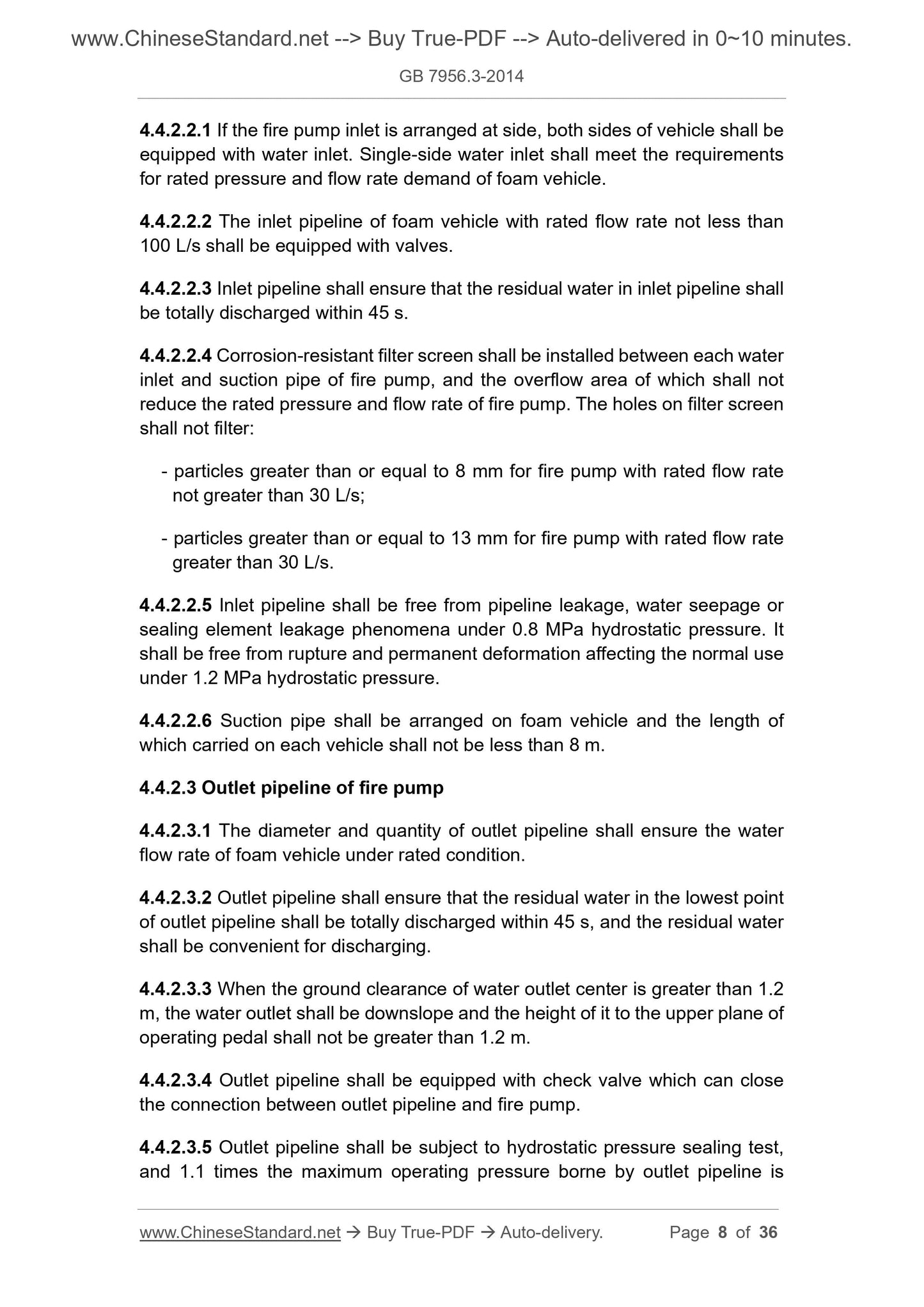
4.4.2.2.1 If the fire pump inlet is arranged at side, both sides of vehicle shall be
equipped with water inlet. Single-side water inlet shall meet the requirements
for rated pressure and flow rate demand of foam vehicle.
4.4.2.2.2 The inlet pipeline of foam vehicle with rated flow rate not less than
100 L/s shall be equipped with valves.
4.4.2.2.3 Inlet pipeline shall ensure that the residual water in inlet pipeline shall
be totally discharged within 45 s.
4.4.2.2.4 Corrosion-resistant filter screen shall be installed between each water
inlet and suction pipe of fire pump, and the overflow area of which shall not
reduce the rated pressure and flow rate of fire pump. The holes on filter screen
shall not filter:
- particles greater than or equal to 8 mm for fire pump with rated flow rate
not greater than 30 L/s;
- particles greater than or equal to 13 mm for fire pump with rated flow rate
greater than 30 L/s.
4.4.2.2.5 Inlet pipeline shall be free from pipeline leakage, water seepage or
sealing element leakage phenomena under 0.8 MPa hydrostatic pressure. It
shall be free from rupture and permanent deformation affecting the normal use
under 1.2 MPa hydrostatic pressure.
4.4.2.2.6 Suction pipe shall be arranged on foam vehicle and the length of
which carried on each vehicle shall not be less than 8 m.
4.4.2.3 Outlet pipeline of fire pump
4.4.2.3.1 The diameter and quantity of outlet pipeline shall ensure the water
flow rate of foam vehicle under rated condition.
4.4.2.3.2 Outlet pipeline shall ensure that the residual water in the lowest point
of outlet pipeline shall be totally discharged within 45 s, and the residual water
shall be convenient for discharging.
4.4.2.3.3 When the ground clearance of water outlet center is greater than 1.2
m, the water outlet shall be downslope and the height of it to the upper plane of
operating pedal shall not be greater than 1.2 m.
4.4.2.3.4 Outlet pipeline shall be equipped with check valve which can close
the connection between outlet pipeline and fire pump.
4.4.2.3.5 Outlet pipeline shall be subject to hydrostatic pressure sealing test,
and 1.1 times the maximum operating pressure borne by outlet pipeline is
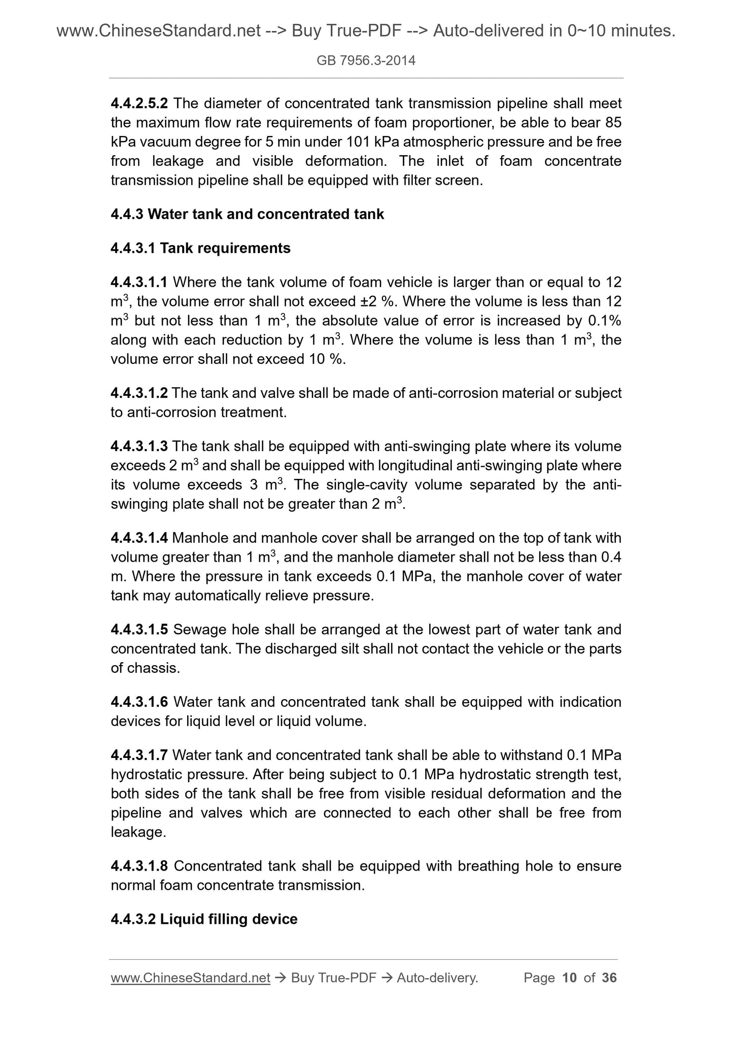
4.4.2.5.2 The diameter of concentrated tank transmission pipeline shall meet
the maximum flow rate requirements of foam proportioner, be able to bear 85
kPa vacuum degree for 5 min under 101 kPa atmospheric pressure and be free
from leakage and visible deformation. The inlet of foam concentrate
transmission pipeline shall be equipped with filter screen.
4.4.3 Water tank and concentrated tank
4.4.3.1 Tank requirements
4.4.3.1.1 Where the tank volume of foam vehicle is larger than or equal to 12
m3, the volume error shall not exceed ±2 %. Where the volume is less than 12
m3 but not less than 1 m3, the absolute value of error is increased by 0.1%
along with each reduction by 1 m3. Where the volume is less than 1 m3, the
volume error shall not exceed 10 %.
4.4.3.1.2 The tank and valve shall be made of anti-corrosion material or subject
to anti-corrosion treatment.
4.4.3.1.3 The tank shall be equipped with anti-swinging plate where its volume
exceeds 2 m3 and shall be equipped with longitudinal anti-swinging plate where
its volume exceeds 3 m3. The single-cavity volume separated by the anti-
swinging plate shall not be greater than 2 m3.
4.4.3.1.4 Manhole and manhole cover shall be arranged on the top of tank with
volume greater than 1 m3, and the manhole diameter shall not be less than 0.4
m. Where the pressure in tank exceeds 0.1 MPa, the manhole cover of water
tank may automatically relieve pressure.
4.4.3.1.5 Sewage hole shall be arranged at the lowest part of water tank and
co...
Share
