1
/
of
12
www.ChineseStandard.us -- Field Test Asia Pte. Ltd.
GB/T 10357.5-2023 English PDF (GB/T10357.5-2023)
GB/T 10357.5-2023 English PDF (GB/T10357.5-2023)
Regular price
$805.00
Regular price
Sale price
$805.00
Unit price
/
per
Shipping calculated at checkout.
Couldn't load pickup availability
GB/T 10357.5-2023: Test of mechanical properties of furniture - Part 5: Strength and durability of storage units
Delivery: 9 seconds. Download (& Email) true-PDF + Invoice.
Get Quotation: Click GB/T 10357.5-2023 (Self-service in 1-minute)
Historical versions (Master-website): GB/T 10357.5-2023
Preview True-PDF (Reload/Scroll-down if blank)
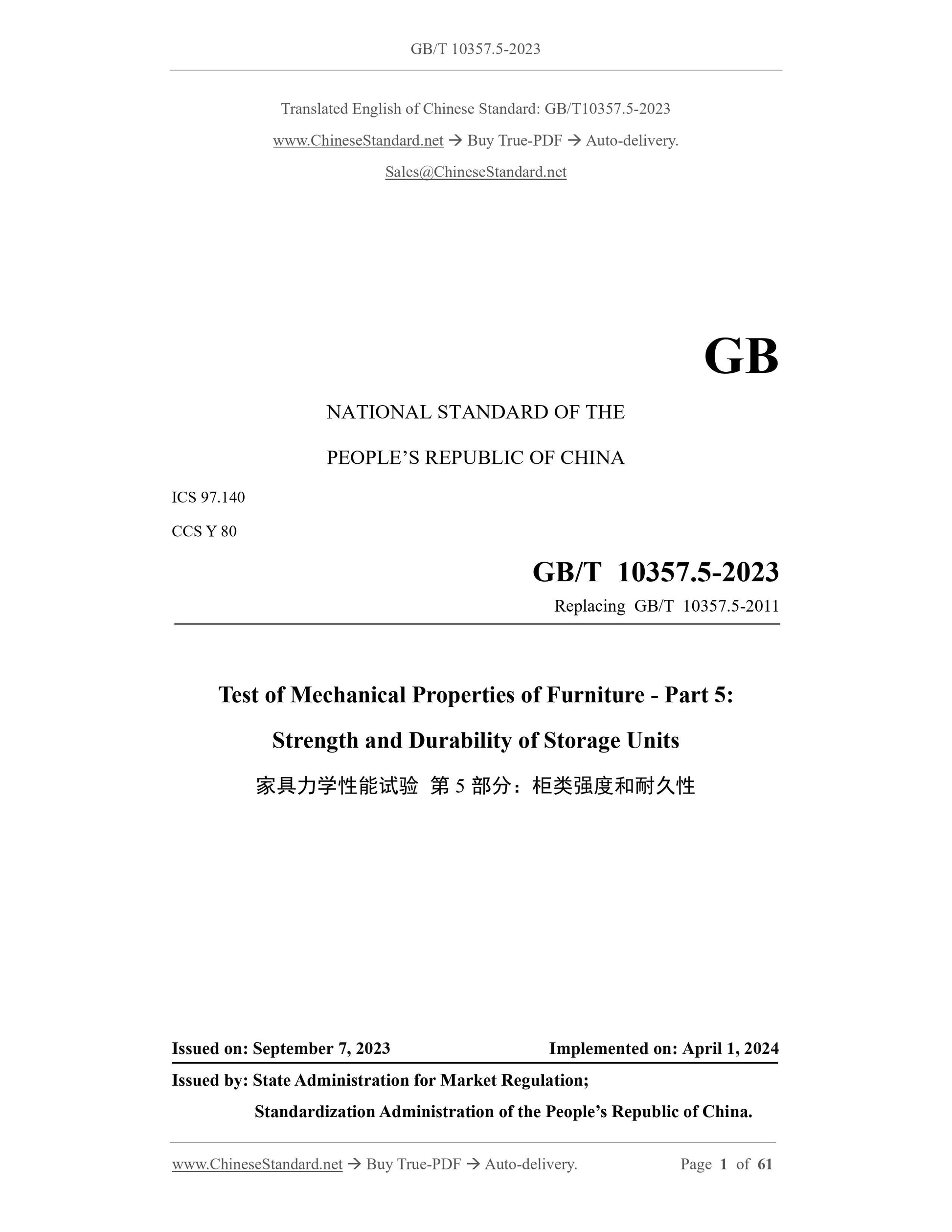
GB/T 10357.5-2023
GB
NATIONAL STANDARD OF THE
PEOPLE’S REPUBLIC OF CHINA
ICS 97.140
CCS Y 80
Replacing GB/T 10357.5-2011
Test of Mechanical Properties of Furniture - Part 5:
Strength and Durability of Storage Units
ISSUED ON: SEPTEMBER 7, 2023
IMPLEMENTED ON: APRIL 1, 2024
Issued by: State Administration for Market Regulation;
Standardization Administration of the People’s Republic of China.
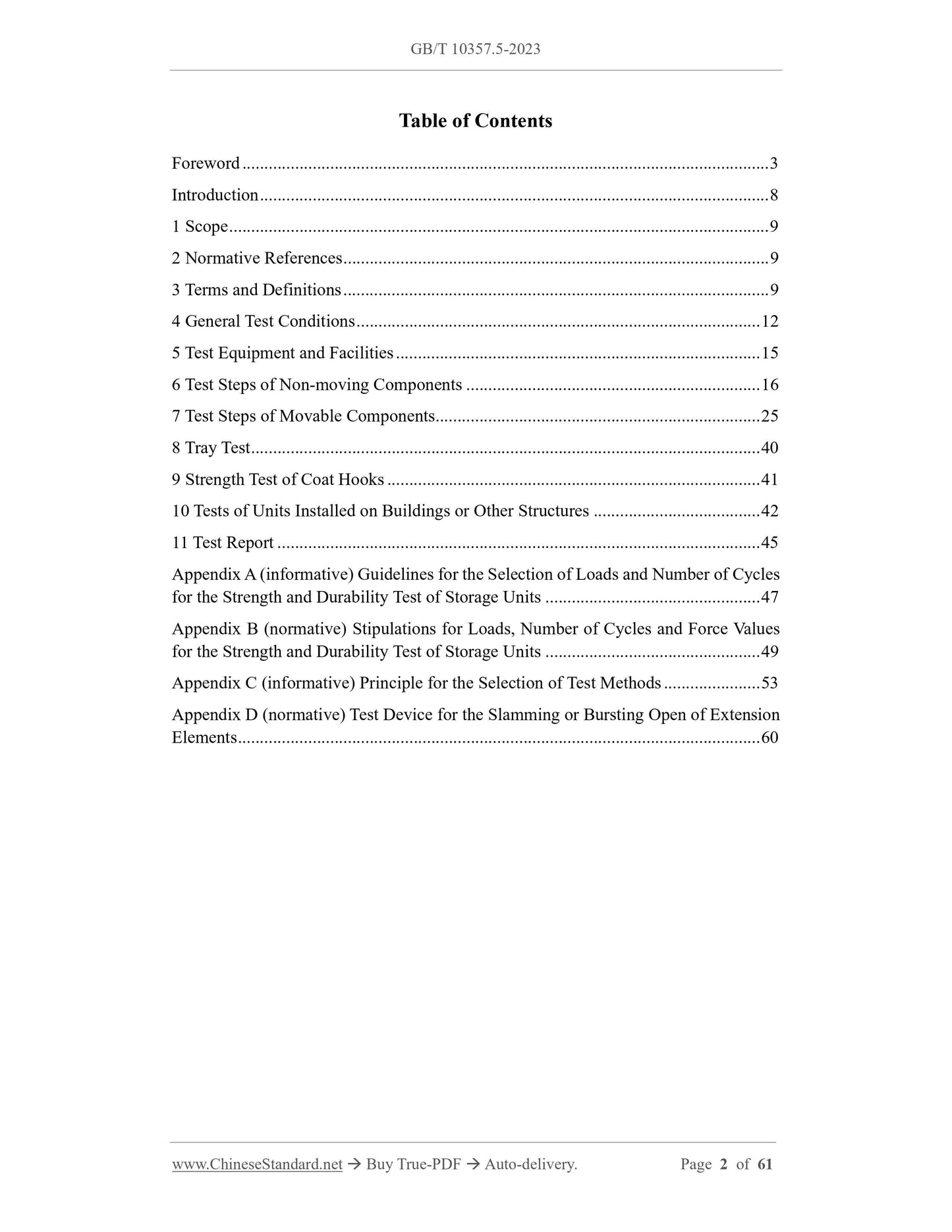
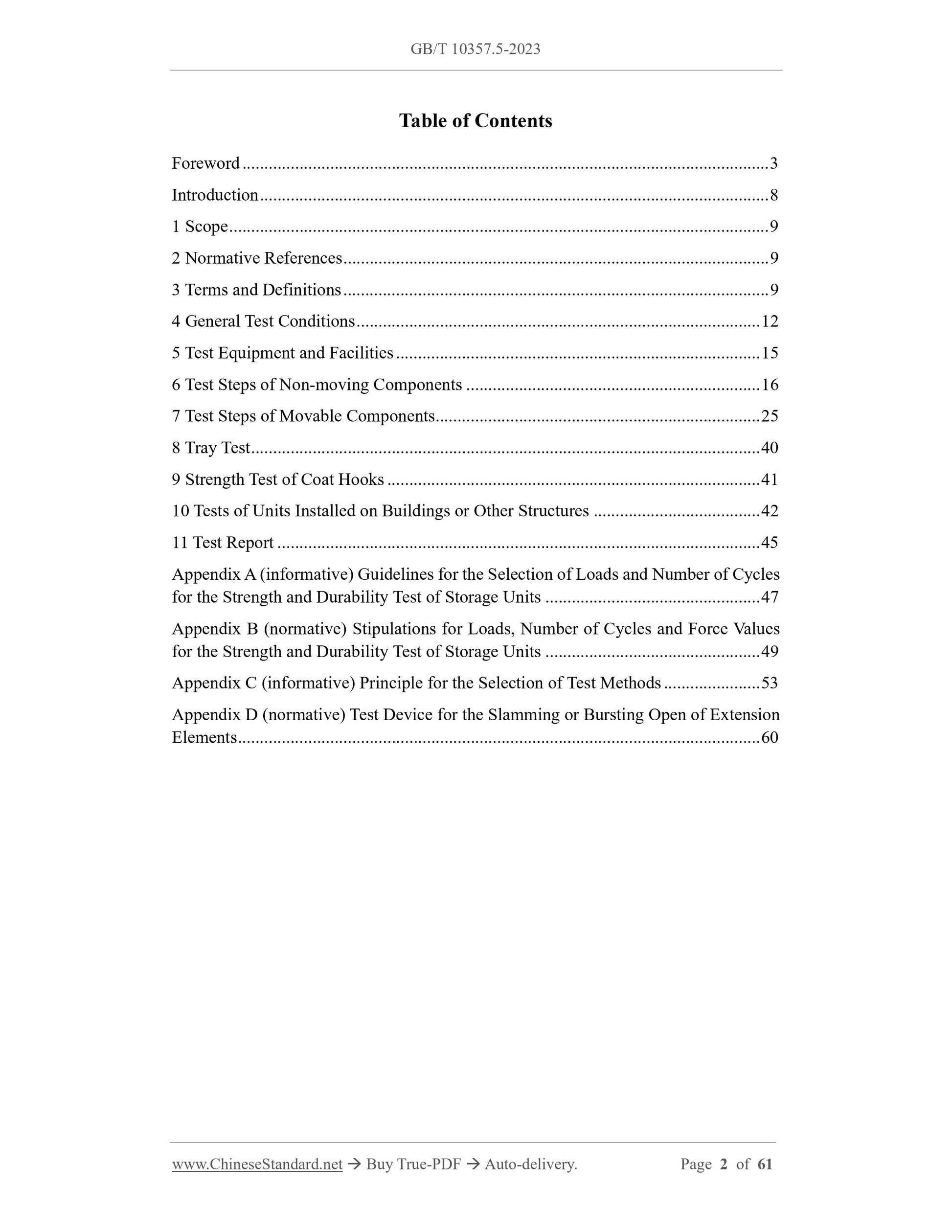
Table of Contents
Foreword ... 3
Introduction ... 8
1 Scope ... 9
2 Normative References ... 9
3 Terms and Definitions ... 9
4 General Test Conditions ... 12
5 Test Equipment and Facilities ... 15
6 Test Steps of Non-moving Components ... 16
7 Test Steps of Movable Components ... 25
8 Tray Test ... 40
9 Strength Test of Coat Hooks ... 41
10 Tests of Units Installed on Buildings or Other Structures ... 42
11 Test Report ... 45
Appendix A (informative) Guidelines for the Selection of Loads and Number of Cycles
for the Strength and Durability Test of Storage Units ... 47
Appendix B (normative) Stipulations for Loads, Number of Cycles and Force Values
for the Strength and Durability Test of Storage Units ... 49
Appendix C (informative) Principle for the Selection of Test Methods ... 53
Appendix D (normative) Test Device for the Slamming or Bursting Open of Extension
Elements ... 60
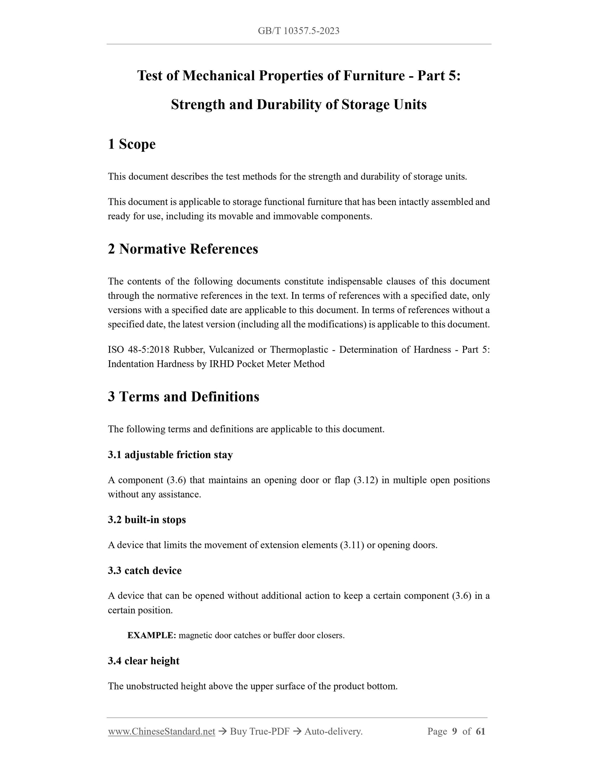
Test of Mechanical Properties of Furniture - Part 5:
Strength and Durability of Storage Units
1 Scope
This document describes the test methods for the strength and durability of storage units.
This document is applicable to storage functional furniture that has been intactly assembled and
ready for use, including its movable and immovable components.
2 Normative References
The contents of the following documents constitute indispensable clauses of this document
through the normative references in the text. In terms of references with a specified date, only
versions with a specified date are applicable to this document. In terms of references without a
specified date, the latest version (including all the modifications) is applicable to this document.
ISO 48-5:2018 Rubber, Vulcanized or Thermoplastic - Determination of Hardness - Part 5:
Indentation Hardness by IRHD Pocket Meter Method
3 Terms and Definitions
The following terms and definitions are applicable to this document.
3.1 adjustable friction stay
A component (3.6) that maintains an opening door or flap (3.12) in multiple open positions
without any assistance.
3.2 built-in stops
A device that limits the movement of extension elements (3.11) or opening doors.
3.3 catch device
A device that can be opened without additional action to keep a certain component (3.6) in a
certain position.
EXAMPLE: magnetic door catches or buffer door closers.
3.4 clear height
The unobstructed height above the upper surface of the product bottom.
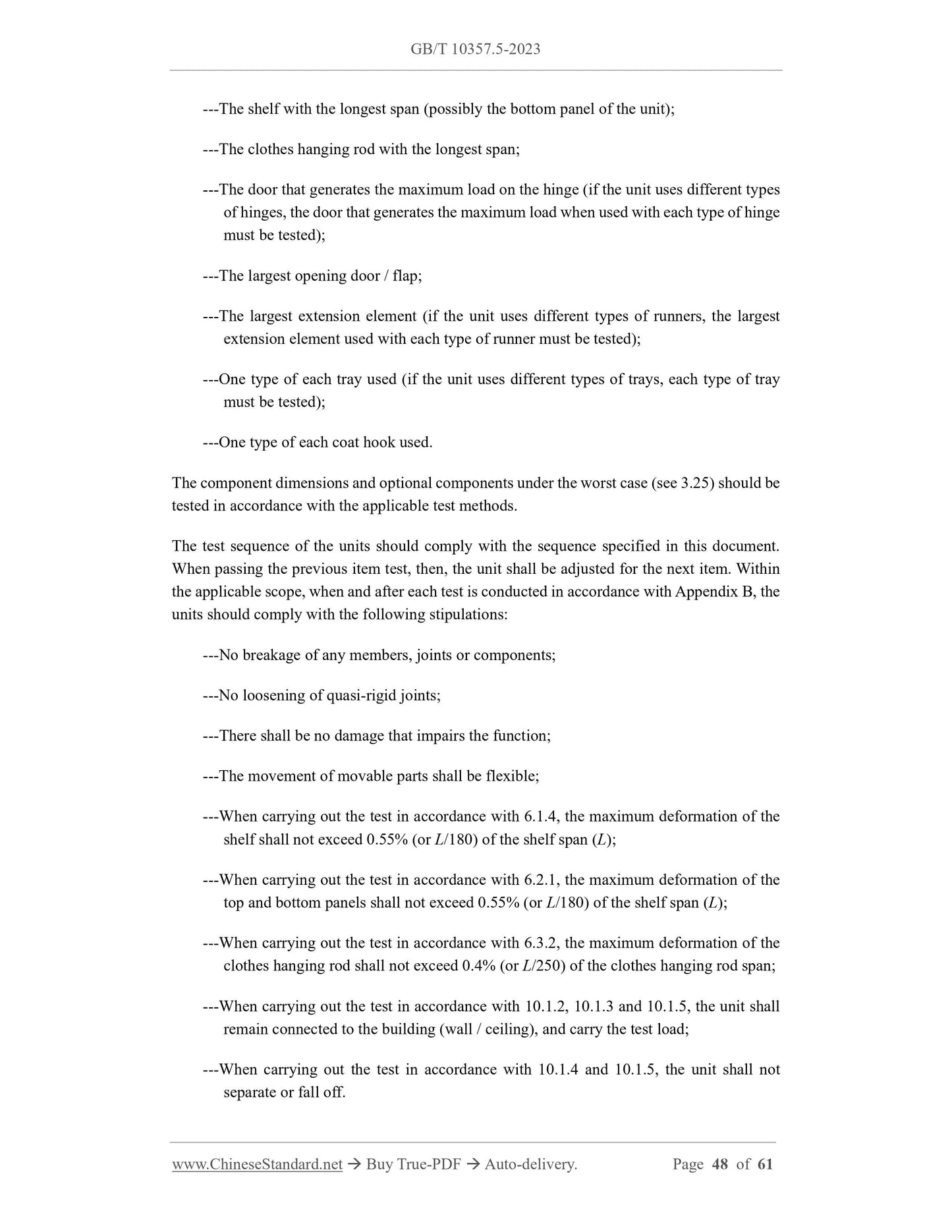
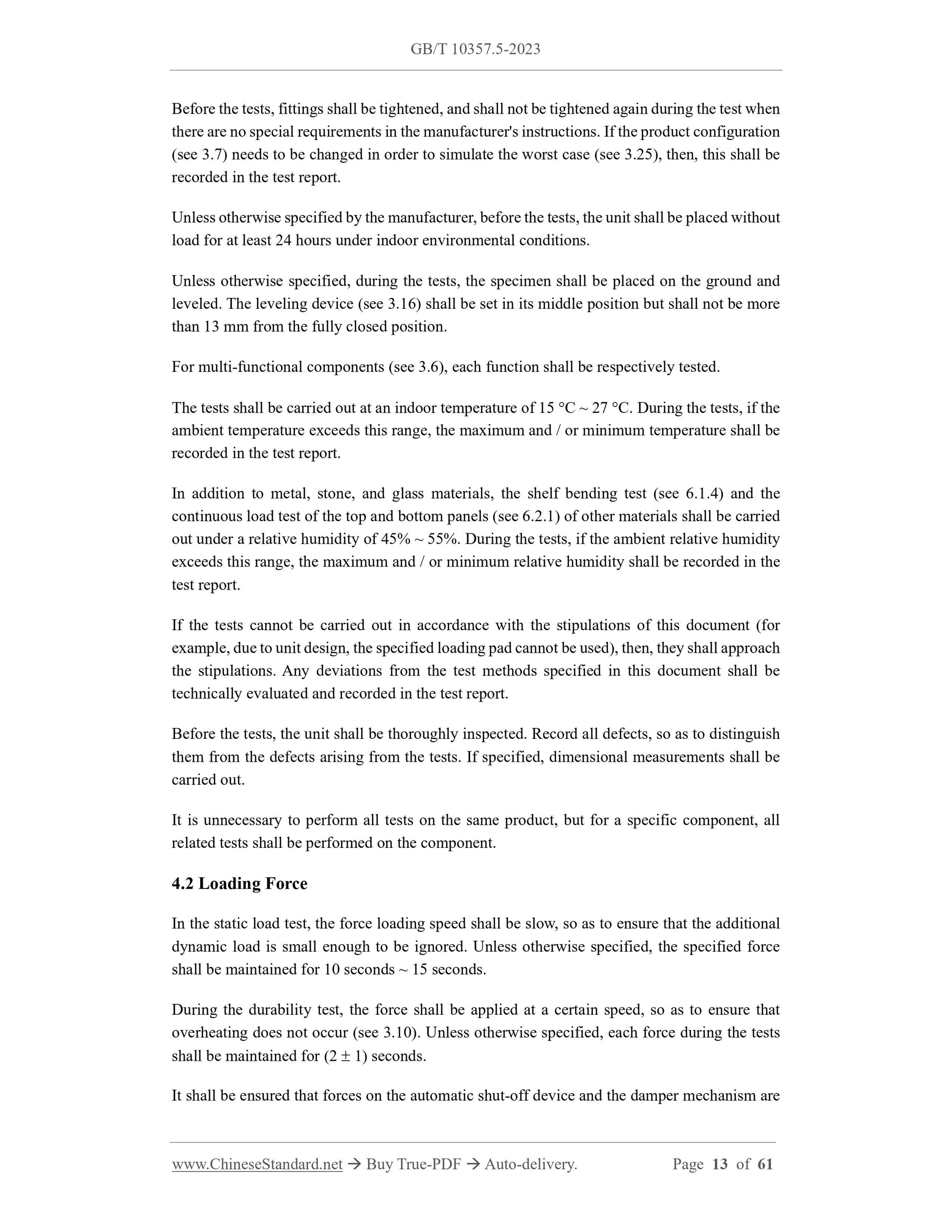
Before the tests, fittings shall be tightened, and shall not be tightened again during the test when
there are no special requirements in the manufacturer's instructions. If the product configuration
(see 3.7) needs to be changed in order to simulate the worst case (see 3.25), then, this shall be
recorded in the test report.
Unless otherwise specified by the manufacturer, before the tests, the unit shall be placed without
load for at least 24 hours under indoor environmental conditions.
Unless otherwise specified, during the tests, the specimen shall be placed on the ground and
leveled. The leveling device (see 3.16) shall be set in its middle position but shall not be more
than 13 mm from the fully closed position.
For multi-functional components (see 3.6), each function shall be respectively tested.
The tests shall be carried out at an indoor temperature of 15 C ~ 27 C. During the tests, if the
ambient temperature exceeds this range, the maximum and / or minimum temperature shall be
recorded in the test report.
In addition to metal, stone, and glass materials, the shelf bending test (see 6.1.4) and the
continuous load test of the top and bottom panels (see 6.2.1) of other materials shall be carried
out under a relative humidity of 45% ~ 55%. During the tests, if the ambient relative humidity
exceeds this range, the maximum and / or minimum relative humidity shall be recorded in the
test report.
If the tests cannot be carried out in accordance with the stipulations of this document (for
example, due to unit design, the specified loading pad cannot be used), then, they shall approach
the stipulations. Any deviations from the test methods specified in this document shall be
technically evaluated and recorded in the test report.
Before the tests, the unit shall be thoroughly inspected. Record all defects, so as to distinguish
them from the defects arising from the tests. If specified, dimensional measurements shall be
carried out.
It is unnecessary to perform all tests on the same product, but for a specific component, all
related tests shall be performed on the component.
4.2 Loading Force
In the static load test, the force loading speed shall be slow, so as to ensure that the additional
dynamic load is small enough to be ignored. Unless otherwise specified, the specified force
shall be maintained for 10 seconds ~ 15 seconds.
During the durability test, the force shall be applied at a certain speed, so as to ensure that
overheating does not occur (see 3.10). Unless otherwise specified, each force during the tests
shall be maintained for (2 1) seconds.
It shall be ensured that forces on the automatic shut-off device and the damper mechanism are
applied under normal operating conditions. The force applied can be replaced by mass. The
conversion relation is 10 N = 1 kg.
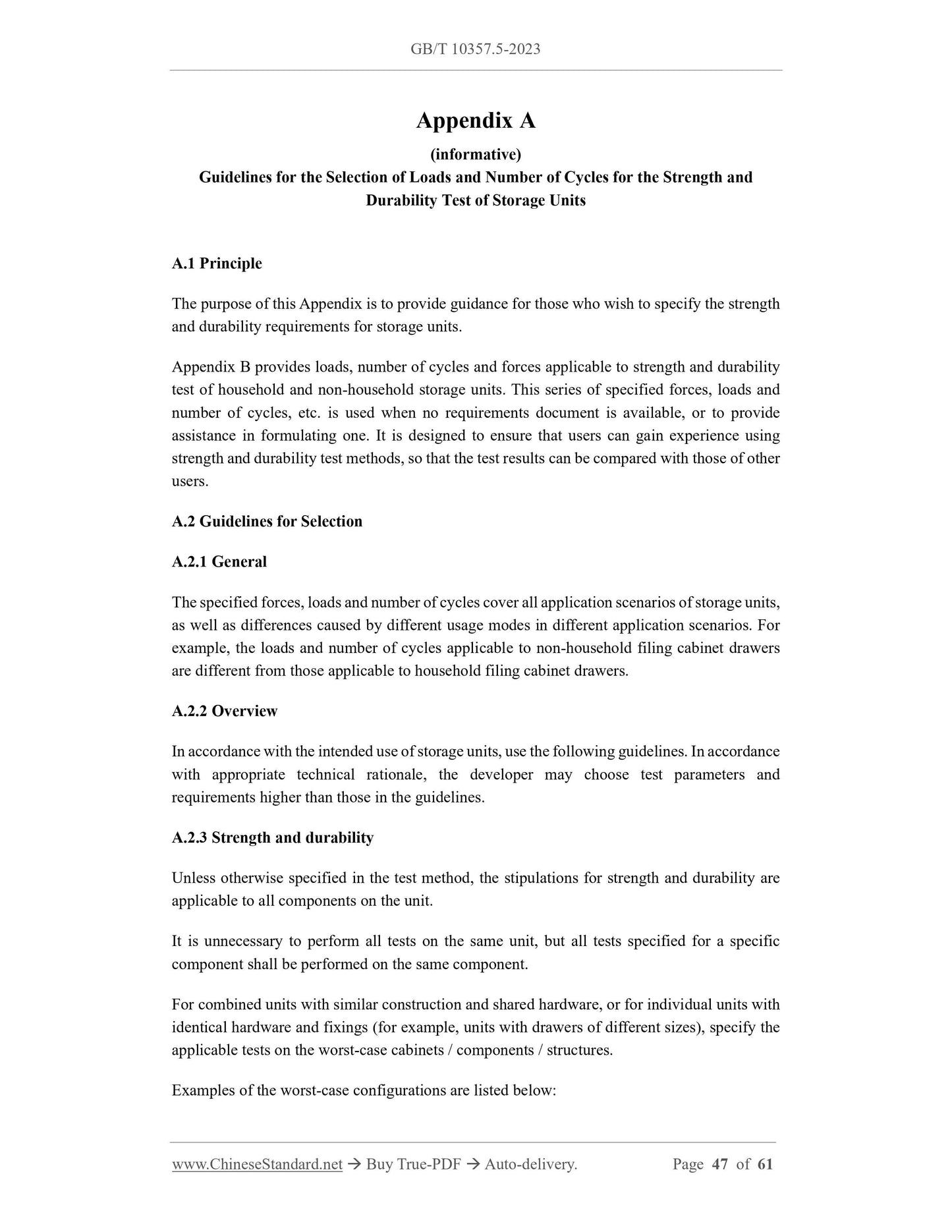
Appendix A elaborates the guidelines for the selection of loads and cycle numbers for the
strength and durability test of storage units.
Appendix B specifies loads, cycle numbers and force values.
Appendix C explains the principle for the selection of the test methods included in this
document.
4.3 Tolerances
Unless otherwise specified, the following tolerances are applicable to this document:
---forces: 5% of nominal force;
---velocities: 10% of nominal velocity;
---masses: 1% of nominal mass;
---dimensions: for all dimensions < 200 mm, the deviation shall be 1 mm from the
nominal dimensions; for other dimensions, the deviation shall be 0.5%; the deviation
of the spherical curvature of a radius of 300 mm on the loading pad (see 5.5) shall be
5 mm;
---angles: 2 of nominal angle.
The position deviation of the loading pad is 5 mm.
The test forces, velocities, masses, dimensions and angles used for the tests shall comply with
the specified nominal values and shall be within the tolerance ranges specified above.
NOTE: for the purpose of uncertainty assessment, when the above tolerances are satisfied, it shall
be deemed that the test results are not adversely affected.
4.4 Control of Unit Movement during Tests
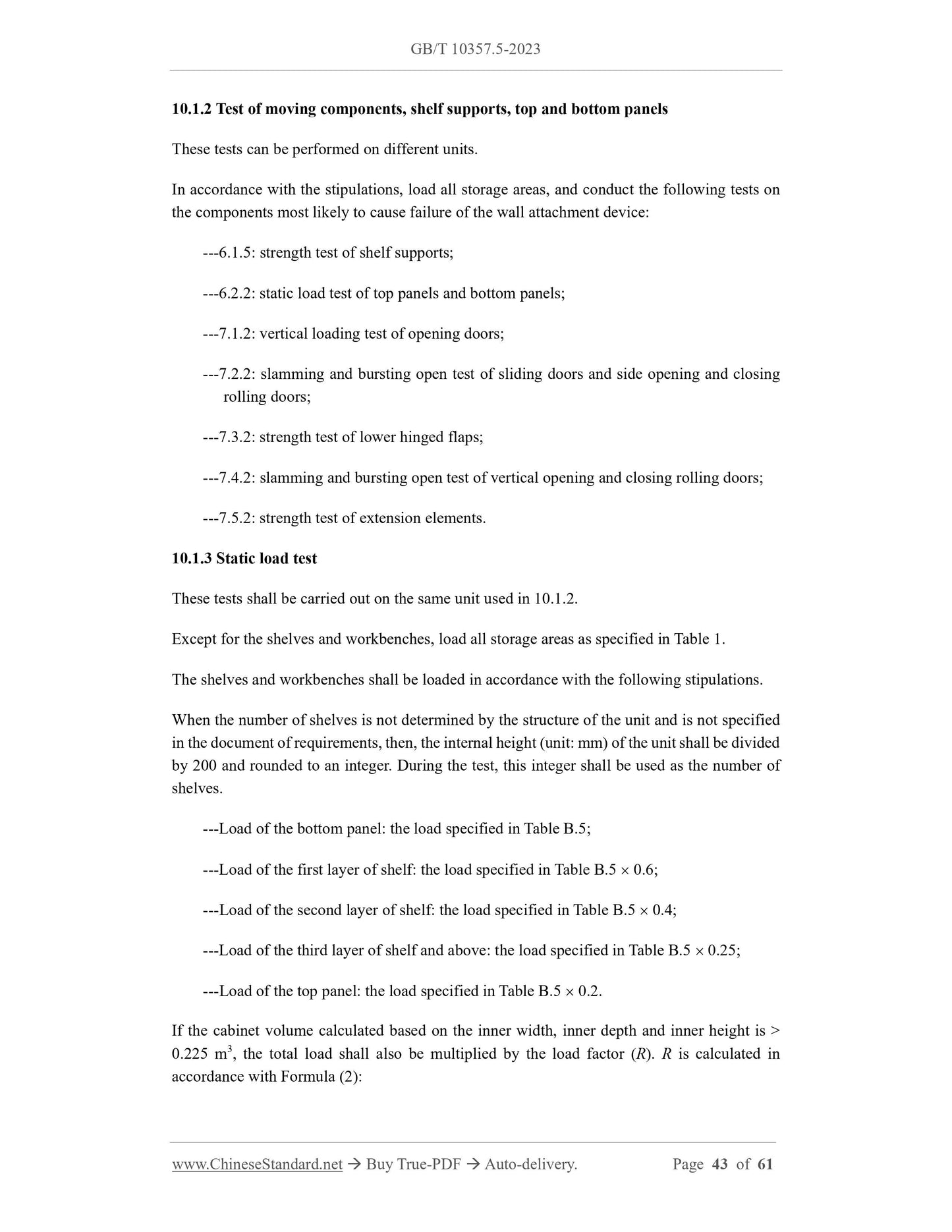
Unless otherwise specified, when carrying out the tests in accordance with the stipulations of
Chapter 6 and Chapter 7, the free standing units (see 3.13) that have a tendency to lose balance
shall be loaded, until they are balanced.
When carrying out the tests in accordance with Chapter 6 (except 6.4.2 and 6.4.3) and Chapter
7, free standing units with a tendency to move shall be restricted by stops (see 5.4).
4.5 Loading
Unless otherwise specified, during the strength and durability tests, non-test storage
components shall be evenly loaded in accordance with the stipulations of Table 1.
Each end of the unit shall be tested once. For the height-adjustable units, the units shall be
adjusted to the lowest position for the test.
NOTE: the front and back sides of the units are not considered as ends.
6.4.3 Caster reciprocation test
Use the load specified in Table 1 to load all components.
At least one caster shall roll over the obstacle (see 5.11) at an average speed of (0.2 0.04) m/s
and travel 1,000 mm. After traveling to the end of 1,000 mm, travel in reverse direction to the
starting point. Repeat this, until the number of cycles specified in Table B.1 is completed, and
a reciprocation is considered a cycle.
7 Test Steps of Movable Components
7.1 Tests of Opening Doors
7.1.1 Overview
The tests are applicable to all doors equipped with vertical hinges, including folding doors.
Use stops to surround the legs or the base of the unit, so as to prevent the unit from moving on
the ground during the tests.
Use the load specified in Table 1 to load all components used for storage, including storage
components on the top panels and doors.
7.1.2 Vertical loading test of opening doors
Use the weights specified in Table B.2 to load the door and hang the weights 100 mm from the
side edge farthest from the door hinge (see Figure 9).
Open and close the door for a total of 10 times. For each opening and closing, from 45 from
the fully closed position to 10 from the fully open position, a reciprocation is considered a
cycle. When the position 10 from the fully open position is > 135, then, open to the 135
position.
Open and close the opening door within the specified angle range, and the opening and closing
times are 3 seconds ~ 5 seconds each.
Doors
7.4.3 Durability test of vertical opening and closing rolling doors
In accordance with the number of times specified in Table B.2, through the force applied on the
vertical centerline, at an average speed not exceeding 0.25 m/s, slowly make full open / full
close reciprocating movement. However, if the rolling door is equipped with a damper
mechanism (see 3.8) and / or a catch device (see 3.3) (including a buffer door closer), then, the
damper mechanism and / or catch device may operate once per cycle.
When moving components, excessive acceleration / deceleration and shock shall be prevented.
The reciprocating speed shall not be greater than 12 cycles/min. When a suspension is required,
the door shall be in the closed position.
7.5 Tests of Extension Elements
7.5.1 Overview
Place stops (see 5.4) around the legs or the base of the units, so as to prevent the units from
moving on the floor during the test.
The test method in 7.5 is not applicable to extension elements with an internal volume < 6.25
dm3.
7.5.2 Strength test of extension elements
Use the load specified in Table 1 to load all components used for storage, including the top
panels.
Use the load specified in Table B.2 to load the extension elements to be tested. When equipped
with suspended filing pockets, use paper or similar substitutes (see 5.9) for loading (see Figure
20).
Pull out the extension element to the limit state. If there is no built-in stop, then, pull out two-
thirds of the inner length (depth) of the extension member, leave one third, or leave at least 100
mm of the extension element inside the unit (see Figure 19).
At a distance of 10 mm from one side in the direction of the centerline of the upper thickness
of the front panel of the extension element, apply the vertical downward static force specified
in Table B.2.
Repeat the test for 10 times.
completely pulled out.
For extension elements without built-in stops, while ensuring that 100 mm is left inside the unit,
they can be pulled out by 300 mm at the maximum.
Use the device specified in Appendix D to slam the extension element for 10 times.
The slamming force shall be applied to a position 10 mm away from the fully closed position
of the extension element. The slamming force shall be applied on the handle of the extension
element. When there are two handles, the force shall be applied on the middle of the two handles.
When the extension element does not have a handle, the force shall be applied on the middle
part of the extension element panel, which is at the same height as the runner (see 3.18). After
each cycle, the bag containing the spherical objects shall be re-adjusted to its original position.
7.5.5 Slamming test of extension elements
The slamming test is only applicable to extension elements equipped with stops in the open
position.
Mount the extension element to be tested on the runner, when using the spherical objects (see
5.8) to load in accordance with the stipulations of Table B.2, or evenly distributing the load of
the suspended filing pockets, use paper or similar substitutes (see 5.9) for loading (see Figure
20).
Open the extension element to 300 mm away from the fully pulled-out position. If the pull-out
length of the extension element is less than 300 mm, then, the extension element shall be fully
closed.
Use the device specified in Appendix D to slam the extension element for 10 times.
The slamming force shall be applied to a position 10 mm away from the fully open position of
the extension element. The slamming force shall be applied on the handle of the extension
element. When there are two handles, the force shall be applied on the middle of the two handles.
When the extension element does not have a handle, the force shall be applied on the middle
part of the extension element panel, which is at the same height as the runner (see 3.18). After
each cycle, the bag containing the spherical objects shall be re-adjusted to its original position.
7.5.6 Strength test of bottom panel of extension elements
Mount the extension element to be tested on the runner or use a similar method to hang the
extension element. In accordance with the stipulations of Table B.2, load it.
At a position about 25 mm high from the middle of the inside of the front panel and the back
panel of the extension element, through the loading pad (see 5.5), apply the static force specified
in Table B.2 (see Figure 22).
Carry out the test for 10 times.
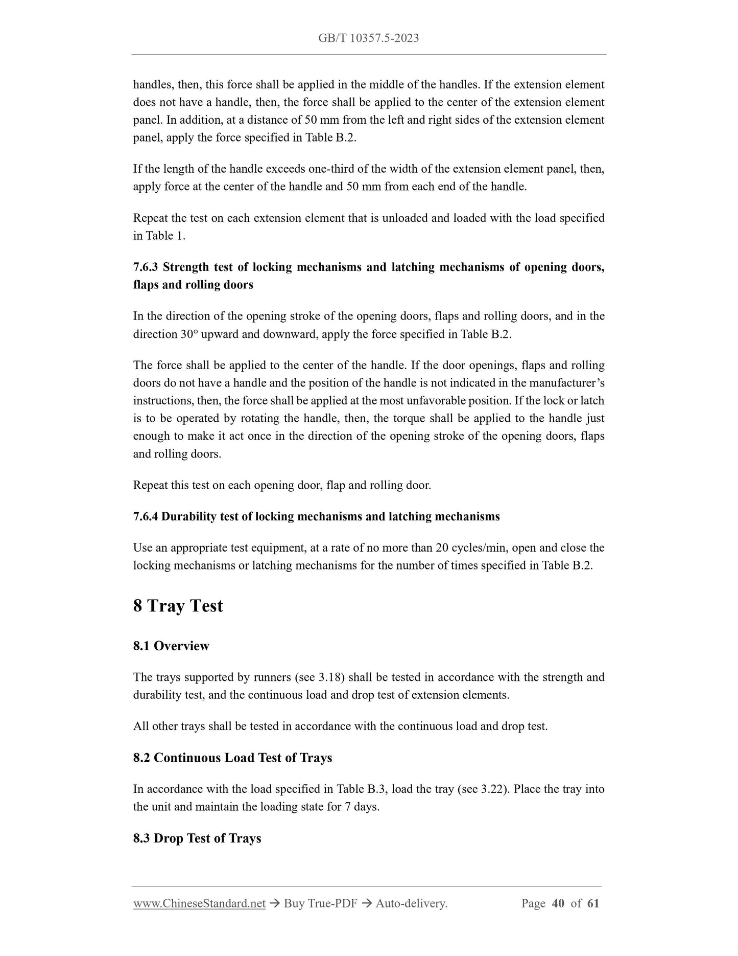
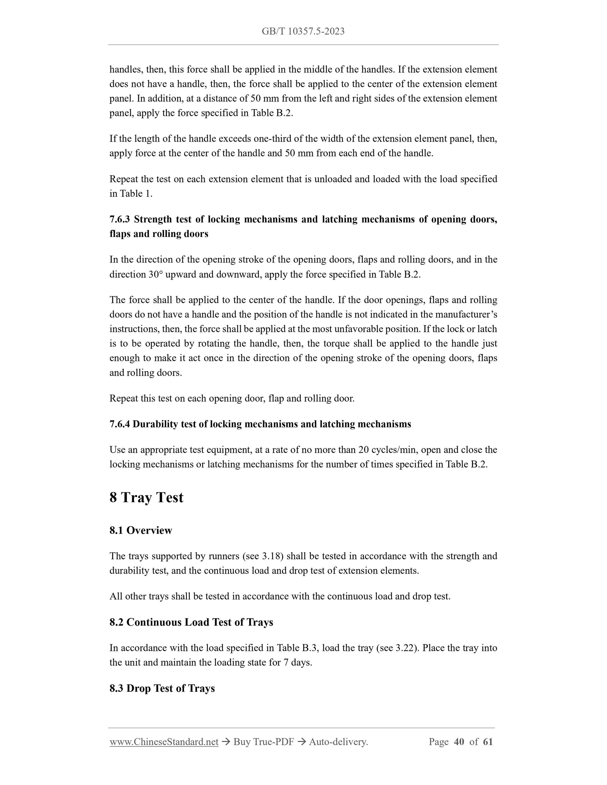
handles, then, this force shall be applied in the middle of the handles. If the extension element
does not have a handle, then, the force shall be applied to the center of the extension element
panel. In addition, at a distance of 50 mm from the left and right sides of the extension element
panel, apply the force specified in Ta...
Share
