1
/
of
9
www.ChineseStandard.us -- Field Test Asia Pte. Ltd.
GB/T 12602-2020 English PDF (GB/T12602-2020)
GB/T 12602-2020 English PDF (GB/T12602-2020)
Regular price
$205.00
Regular price
Sale price
$205.00
Unit price
/
per
Shipping calculated at checkout.
Couldn't load pickup availability
GB/T 12602-2020: Safety devices against over loading for lifting appliances
Delivery: 9 seconds. Download (& Email) true-PDF + Invoice.
Get Quotation: Click GB/T 12602-2020 (Self-service in 1-minute)
Historical versions (Master-website): GB/T 12602-2020
Preview True-PDF (Reload/Scroll-down if blank)
GB/T 12602-2020
GB
NATIONAL STANDARD OF THE
PEOPLE’S REPUBLIC OF CHINA
ICS 53.020.30
J 80
Replacing GB/T 12602-2009
Safety devices against over loading for lifting
appliances
ISSUED ON: MARCH 31, 2020
IMPLEMENTED ON: OCTOBER 01, 2020
Issued by: State Administration for Market Regulation;
Standardization Administration of PRC.
Table of Contents
Foreword ... 3
1 Scope ... 5
2 Normative references ... 5
3 Terms and definitions ... 6
4 Technical requirements ... 7
5 Test method ... 14
6 Inspection rules ... 20
7 Marking, packaging, transportation and storage ... 22
Safety devices against over loading for lifting
appliances
1 Scope
This standard specifies the terms and definitions, technical requirements, test
methods, inspection rules, markings, packaging, transportation and storage of
overload protection devices for lifting appliances.
This standard applies to overload protection devices (hereinafter referred to as
"devices") used by electric hoists, bridge cranes, gantry cranes, mobile cranes,
tower cranes and jib cranes. The overload protection devices used by other
types of lifting appliances may refer to it.
2 Normative references
The following documents are essential to the application of this document. For
the dated documents, only the versions with the dates indicated are applicable
to this document; for the undated documents, only the latest version (including
all the amendments) are applicable to this standard.
GB/T 2423.4-2008 Environmental testing for electric and electronic products
- Part 2: Test method - Test Db: Damp heat, cyclic (12h + 12h cycle)
GB/T 3811-2008 Design rules for cranes
GB/T 4208-2017 Degrees of protection provided by enclosure (IP code)
GB/T 8923.1-2011 Preparation of steel substrates before application of
paints and related products - Visual assessment of surface cleanliness - Part
1: Rust grades and preparation grades of uncoated steel surface and steel
surface after comprehensive removal of the original coating
GB/T 13306 Plates
GB/T 13384 General specifications for packing of mechanical and electrical
product
GB/T 14048.1-2012 Low-voltage switchgear and control equipment - Part 1:
General
GB/T 17626.5 Electromagnetic compatibility - Testing and measurement
techniques - Surge immunity test
3.6
Configuration
For mobile cranes, tower cranes and jib cranes, etc., the combination and
arrangement of structural parts, counterweights, supports or outriggers,
hook pulley block winding systems, as well as the combinations, positioning
and installation of similar members as carried out according to the
manufacturer's instructions and operation preparations.
3.7
Dangerous directions
When the lifting appliance is overloaded, the direction which makes the load
or torque increase and other directions that aggravate dangerous actions.
3.8
Safety directions
When the lifting appliances is overloaded, the direction which makes the load
or torque decrease and other directions that reduce dangerous actions.
4 Technical requirements
4.1 Environmental conditions
The device shall work normally under the following environmental conditions:
a) Temperature: -20 °C ~ 60 °C;
b) Relative humidity: 90% at 20 °C;
c) Altitude: Not more than 2000 m.
Note: When the above environmental conditions are exceeded, the user and
the manufacturer shall negotiate and resolve it.
4.2 Basic requirements
4.2.1 Component identification
The exposed operable elements (switches, knobs, etc.) of the device shall have
clear and permanent external markings. The identification shall be clear. The
text identification shall have at least simplified Chinese.
4.2.2 Material and structure
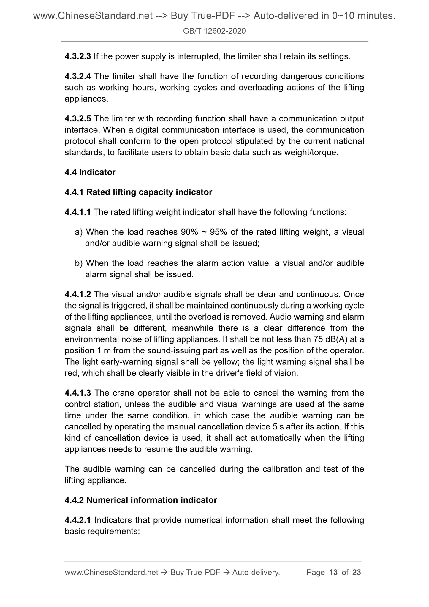
4.3.2.3 If the power supply is interrupted, the limiter shall retain its settings.
4.3.2.4 The limiter shall have the function of recording dangerous conditions
such as working hours, working cycles and overloading actions of the lifting
appliances.
4.3.2.5 The limiter with recording function shall have a communication output
interface. When a digital communication interface is used, the communication
protocol shall conform to the open protocol stipulated by the current national
standards, to facilitate users to obtain basic data such as weight/torque.
4.4 Indicator
4.4.1 Rated lifting capacity indicator
4.4.1.1 The rated lifting weight indicator shall have the following functions:
a) When the load reaches 90% ~ 95% of the rated lifting weight, a visual
and/or audible warning signal shall be issued;
b) When the load reaches the alarm action value, a visual and/or audible
alarm signal shall be issued.
4.4.1.2 The visual and/or audible signals shall be clear and continuous. Once
the signal is triggered, it shall be maintained continuously during a working cycle
of the lifting appliances, until the overload is removed. Audio warning and alarm
signals shall be different, meanwhile there is a clear difference from the
environmental noise of lifting appliances. It shall be not less than 75 dB(A) at a
position 1 m from the sound-issuing part as well as the position of the operator.
The light early-warning signal shall be yellow; the light warning signal shall be
red, which shall be clearly visible in the driver's field of vision.
4.4.1.3 The crane operator shall not be able to cancel the warning from the
control station, unless the audible and visual warnings are used at the same
time under the same condition, in which case the audible warning can be
cancelled by operating the manual cancellation device 5 s after its action. If this
kind of cancellation device is used, it shall act automatically when the lifting
appliances needs to resume the audible warning.
The audible warning can be cancelled during the calibration and test of the
lifting appliance.
4.4.2 Numerical information indicator
4.4.2.1 Indicators that provide numerical information shall meet the following
basic requirements:
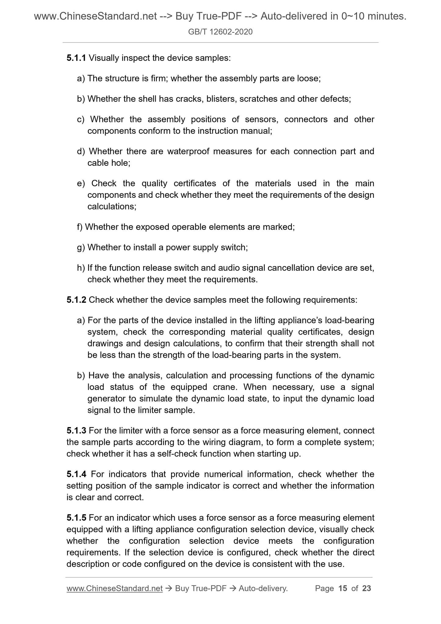
5.1.1 Visually inspect the device samples:
a) The structure is firm; whether the assembly parts are loose;
b) Whether the shell has cracks, blisters, scratches and other defects;
c) Whether the assembly positions of sensors, connectors and other
components conform to the instruction manual;
d) Whether there are waterproof measures for each connection part and
cable hole;
e) Check the quality certificates of the materials used in the main
components and check whether they meet the requirements of the design
calculations;
f) Whether the exposed operable elements are marked;
g) Whether to install a power supply switch;
h) If the function release switch and audio signal cancellation device are set,
check whether they meet the requirements.
5.1.2 Check whether the device samples meet the following requirements:
a) For the parts of the device installed in the lifting appliance’s load-bearing
system, check the corresponding material quality certificates, design
drawings and design calculations, to confirm that their strength shall not
be less than the strength of the load-bearing parts in the system.
b) Have the analysis, calculation and processing functions of the dynamic
load status of the equipped crane. When necessary, use a signal
generator to simulate the dynamic load state, to input the dynamic load
signal to the limiter sample.
5.1.3 For the limiter with a force sensor as a force measuring element, connect
the sample parts according to the wiring diagram, to form a complete system;
check whether it has a self-check function when starting up.
5.1.4 For indicators that provide numerical information, check whether the
setting position of the sample indicator is correct and whether the information
is clear and correct.
5.1.5 For an indicator which uses a force sensor as a force measuring element
equipped with a lifting appliance configuration selection device, visually check
whether the configuration selection device meets the configuration
requirements. If the selection device is configured, check whether the direct
description or code configured on the device is consistent with the use.
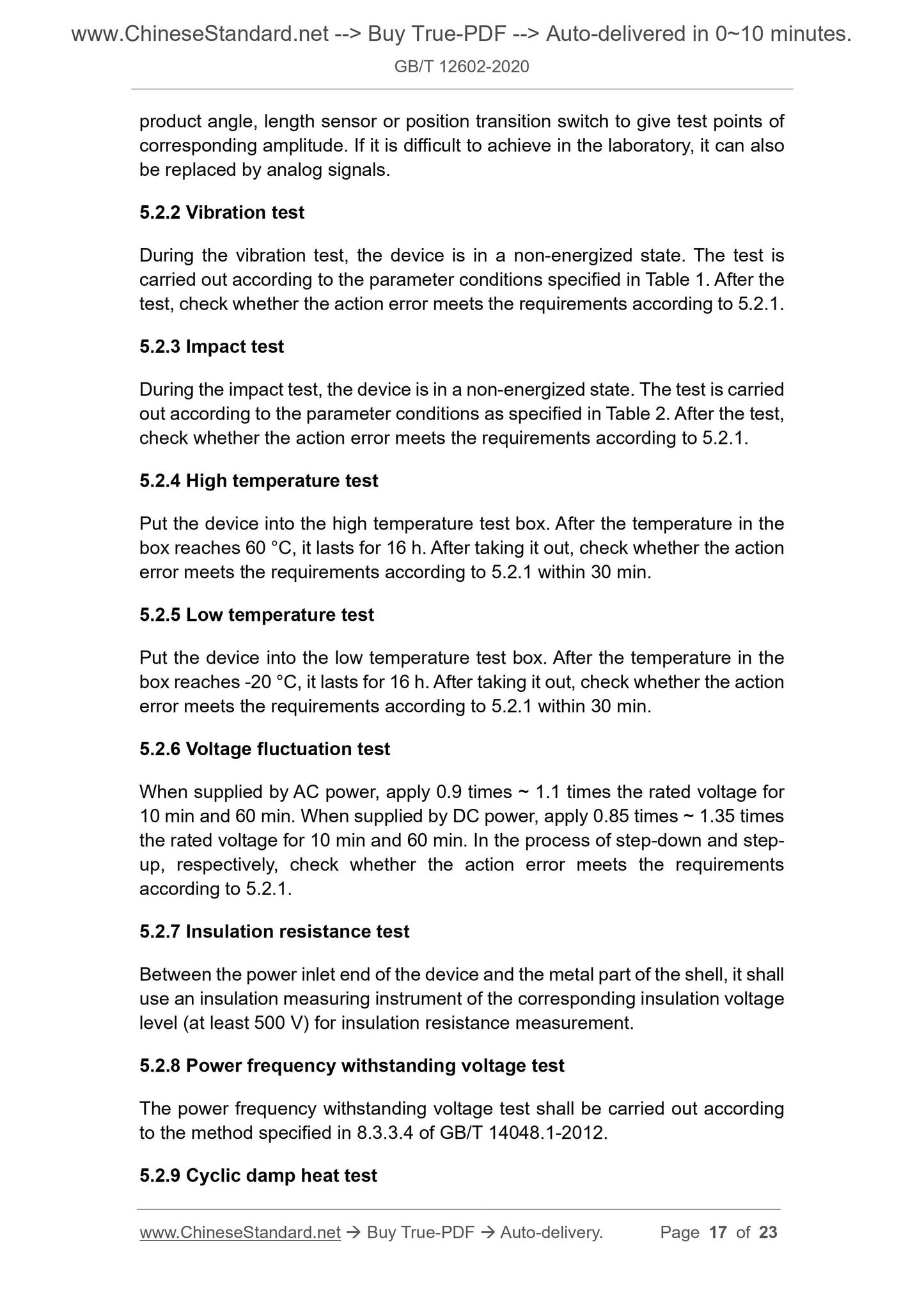
product angle, length sensor or position transition switch to give test points of
corresponding amplitude. If it is difficult to achieve in the laboratory, it can also
be replaced by analog signals.
5.2.2 Vibration test
During the vibration test, the device is in a non-energized state. The test is
carried out according to the parameter conditions specified in Table 1. After the
test, check whether the action error meets the requirements according to 5.2.1.
5.2.3 Impact test
During the impact test, the device is in a non-energized state. The test is carried
out according to the parameter conditions as specified in Table 2. After the test,
check whether the action error meets the requirements according to 5.2.1.
5.2.4 High temperature test
Put the device into the high temperature test box. After the temperature in the
box reaches 60 °C, it lasts for 16 h. After taking it out, check whether the action
error meets the requirements according to 5.2.1 within 30 min.
5.2.5 Low temperature test
Put the device into the low temperature test box. After the temperature in the
box reaches -20 °C, it lasts for 16 h. After taking it out, check whether the action
error meets the requirements according to 5.2.1 within 30 min.
5.2.6 Voltage fluctuation test
When supplied by AC power, apply 0.9 times ~ 1.1 times the rated voltage for
10 min and 60 min. When supplied by DC power, apply 0.85 times ~ 1.35 times
the rated voltage for 10 min and 60 min. In the process of step-down and step-
up, respectively, check whether the action error meets the requirements
according to 5.2.1.
5.2.7 Insulation resistance test
Between the power inlet end of the device and the metal part of the shell, it shall
use an insulation measuring instrument of the corresponding insulation voltage
level (at least 500 V) for insulation resistance measurement.
5.2.8 Power frequency withstanding voltage test
The power frequency withstanding voltage test shall be carried out according
to the method specified in 8.3.3.4 of GB/T 14048.1-2012.
5.2.9 Cyclic damp heat test
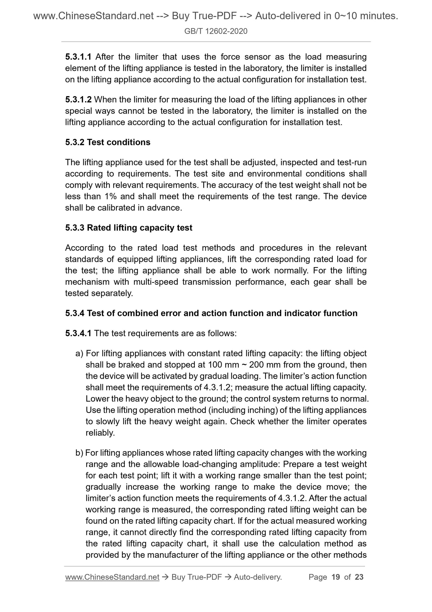
5.3.1.1 After the limiter that uses the force sensor as the load measuring
element of the lifting appliance is tested in the laboratory, the limiter is installed
on the lifting appliance according to the actual configuration for installation test.
5.3.1.2 When the limiter for measuring the load of the lifting appliances in other
special ways cannot be tested in the laboratory, the limiter is installed on the
lifting appliance according to the actual configuration for installation test.
5.3.2 Test conditions
The lifting appliance used for the test shall be adjusted, inspected and test-run
according to requirements. The test site and environmental conditions shall
comply with relevant requirements. The accuracy of the test weight shall not be
less than 1% and shall meet the requirements of the test range. The device
shall be calibrated in advance.
5.3.3 Rated lifting capacity test
According to the rated load test methods and procedures in the relevant
standards of equipped lifting appliances, lift the corresponding rated load for
the test; the lifting appliance shall be able to work normally. For the lifting
mechanism with multi-speed transmission performance, each gear shall be
tested separately.
5.3.4 Test of combined error and action function and indicator function
5.3.4.1 The test requirements are as follows:
a) For lifting appliances with constant rated lifting capacity: the lifting object
shall be braked and stopped at 100 mm ~ 200 mm from the ground, then
the device will be activated by gradual loading. The limiter’s action function
shall meet the requirements of 4.3.1.2; measure the actual lifting capacity.
Lower the heavy object to the ground; the control system returns to normal.
Use the lifting operation method (including inching) of the lifting appliances
to slowly lift the heavy weight again. Check whether the limiter operates
reliably.
b) For lifting appliances whose rated lifting capacity changes with the working
range and the allowable load-changing amplitude: Prepare a test weight
for each test point; lift it with a working range smaller than the test point;
gradually increase the working range to make the device move; the
limiter’s action function meets the requirements of 4.3.1.2. After the actual
working range is measured, the corresponding rated lifting weight can be
found on the rated lifting capacity chart. If for the actual measured working
range, it cannot directly find the corresponding rated lifting capacity from
the rated lifting capacity chart, it shall use the calculation method as
provided by the manufacturer of the lifting appliance or the other methods
b) After formal production, if there are major changes in product structure,
materials, processes, functions, etc., which may affect product
performance;
c) There is a big difference between the exit-factory inspection results and
the last type inspection;
d) When the product resumes production after stopping production for 1 year;
e) When the national quality supervision agency puts forward a requirement
for type inspection.
6.3.2 Type inspection items are as shown in Table 7.
7 Marking, packaging, transportation and storage
7.1 Marking
Signs shall be installed at the obvious positions of the products; their
requirements shall meet the requirements of GB/T 13306. The signs shall at
least indicate the following:
a) Name and model;
b) The name of the manufacturer;
c) Product number;
d) Date of exit-factory.
7.2 Packaging
The packaging of the product shall meet the requirements of GB/T 13384. At
least the following accompanying documents shall be attached when the
product is exit-factory:
a) Product qualification certificate;
b) Product instruction manual.
7.3 Transportation and storage
7.3.1 During...
Delivery: 9 seconds. Download (& Email) true-PDF + Invoice.
Get Quotation: Click GB/T 12602-2020 (Self-service in 1-minute)
Historical versions (Master-website): GB/T 12602-2020
Preview True-PDF (Reload/Scroll-down if blank)
GB/T 12602-2020
GB
NATIONAL STANDARD OF THE
PEOPLE’S REPUBLIC OF CHINA
ICS 53.020.30
J 80
Replacing GB/T 12602-2009
Safety devices against over loading for lifting
appliances
ISSUED ON: MARCH 31, 2020
IMPLEMENTED ON: OCTOBER 01, 2020
Issued by: State Administration for Market Regulation;
Standardization Administration of PRC.
Table of Contents
Foreword ... 3
1 Scope ... 5
2 Normative references ... 5
3 Terms and definitions ... 6
4 Technical requirements ... 7
5 Test method ... 14
6 Inspection rules ... 20
7 Marking, packaging, transportation and storage ... 22
Safety devices against over loading for lifting
appliances
1 Scope
This standard specifies the terms and definitions, technical requirements, test
methods, inspection rules, markings, packaging, transportation and storage of
overload protection devices for lifting appliances.
This standard applies to overload protection devices (hereinafter referred to as
"devices") used by electric hoists, bridge cranes, gantry cranes, mobile cranes,
tower cranes and jib cranes. The overload protection devices used by other
types of lifting appliances may refer to it.
2 Normative references
The following documents are essential to the application of this document. For
the dated documents, only the versions with the dates indicated are applicable
to this document; for the undated documents, only the latest version (including
all the amendments) are applicable to this standard.
GB/T 2423.4-2008 Environmental testing for electric and electronic products
- Part 2: Test method - Test Db: Damp heat, cyclic (12h + 12h cycle)
GB/T 3811-2008 Design rules for cranes
GB/T 4208-2017 Degrees of protection provided by enclosure (IP code)
GB/T 8923.1-2011 Preparation of steel substrates before application of
paints and related products - Visual assessment of surface cleanliness - Part
1: Rust grades and preparation grades of uncoated steel surface and steel
surface after comprehensive removal of the original coating
GB/T 13306 Plates
GB/T 13384 General specifications for packing of mechanical and electrical
product
GB/T 14048.1-2012 Low-voltage switchgear and control equipment - Part 1:
General
GB/T 17626.5 Electromagnetic compatibility - Testing and measurement
techniques - Surge immunity test
3.6
Configuration
For mobile cranes, tower cranes and jib cranes, etc., the combination and
arrangement of structural parts, counterweights, supports or outriggers,
hook pulley block winding systems, as well as the combinations, positioning
and installation of similar members as carried out according to the
manufacturer's instructions and operation preparations.
3.7
Dangerous directions
When the lifting appliance is overloaded, the direction which makes the load
or torque increase and other directions that aggravate dangerous actions.
3.8
Safety directions
When the lifting appliances is overloaded, the direction which makes the load
or torque decrease and other directions that reduce dangerous actions.
4 Technical requirements
4.1 Environmental conditions
The device shall work normally under the following environmental conditions:
a) Temperature: -20 °C ~ 60 °C;
b) Relative humidity: 90% at 20 °C;
c) Altitude: Not more than 2000 m.
Note: When the above environmental conditions are exceeded, the user and
the manufacturer shall negotiate and resolve it.
4.2 Basic requirements
4.2.1 Component identification
The exposed operable elements (switches, knobs, etc.) of the device shall have
clear and permanent external markings. The identification shall be clear. The
text identification shall have at least simplified Chinese.
4.2.2 Material and structure
4.3.2.3 If the power supply is interrupted, the limiter shall retain its settings.
4.3.2.4 The limiter shall have the function of recording dangerous conditions
such as working hours, working cycles and overloading actions of the lifting
appliances.
4.3.2.5 The limiter with recording function shall have a communication output
interface. When a digital communication interface is used, the communication
protocol shall conform to the open protocol stipulated by the current national
standards, to facilitate users to obtain basic data such as weight/torque.
4.4 Indicator
4.4.1 Rated lifting capacity indicator
4.4.1.1 The rated lifting weight indicator shall have the following functions:
a) When the load reaches 90% ~ 95% of the rated lifting weight, a visual
and/or audible warning signal shall be issued;
b) When the load reaches the alarm action value, a visual and/or audible
alarm signal shall be issued.
4.4.1.2 The visual and/or audible signals shall be clear and continuous. Once
the signal is triggered, it shall be maintained continuously during a working cycle
of the lifting appliances, until the overload is removed. Audio warning and alarm
signals shall be different, meanwhile there is a clear difference from the
environmental noise of lifting appliances. It shall be not less than 75 dB(A) at a
position 1 m from the sound-issuing part as well as the position of the operator.
The light early-warning signal shall be yellow; the light warning signal shall be
red, which shall be clearly visible in the driver's field of vision.
4.4.1.3 The crane operator shall not be able to cancel the warning from the
control station, unless the audible and visual warnings are used at the same
time under the same condition, in which case the audible warning can be
cancelled by operating the manual cancellation device 5 s after its action. If this
kind of cancellation device is used, it shall act automatically when the lifting
appliances needs to resume the audible warning.
The audible warning can be cancelled during the calibration and test of the
lifting appliance.
4.4.2 Numerical information indicator
4.4.2.1 Indicators that provide numerical information shall meet the following
basic requirements:
5.1.1 Visually inspect the device samples:
a) The structure is firm; whether the assembly parts are loose;
b) Whether the shell has cracks, blisters, scratches and other defects;
c) Whether the assembly positions of sensors, connectors and other
components conform to the instruction manual;
d) Whether there are waterproof measures for each connection part and
cable hole;
e) Check the quality certificates of the materials used in the main
components and check whether they meet the requirements of the design
calculations;
f) Whether the exposed operable elements are marked;
g) Whether to install a power supply switch;
h) If the function release switch and audio signal cancellation device are set,
check whether they meet the requirements.
5.1.2 Check whether the device samples meet the following requirements:
a) For the parts of the device installed in the lifting appliance’s load-bearing
system, check the corresponding material quality certificates, design
drawings and design calculations, to confirm that their strength shall not
be less than the strength of the load-bearing parts in the system.
b) Have the analysis, calculation and processing functions of the dynamic
load status of the equipped crane. When necessary, use a signal
generator to simulate the dynamic load state, to input the dynamic load
signal to the limiter sample.
5.1.3 For the limiter with a force sensor as a force measuring element, connect
the sample parts according to the wiring diagram, to form a complete system;
check whether it has a self-check function when starting up.
5.1.4 For indicators that provide numerical information, check whether the
setting position of the sample indicator is correct and whether the information
is clear and correct.
5.1.5 For an indicator which uses a force sensor as a force measuring element
equipped with a lifting appliance configuration selection device, visually check
whether the configuration selection device meets the configuration
requirements. If the selection device is configured, check whether the direct
description or code configured on the device is consistent with the use.
product angle, length sensor or position transition switch to give test points of
corresponding amplitude. If it is difficult to achieve in the laboratory, it can also
be replaced by analog signals.
5.2.2 Vibration test
During the vibration test, the device is in a non-energized state. The test is
carried out according to the parameter conditions specified in Table 1. After the
test, check whether the action error meets the requirements according to 5.2.1.
5.2.3 Impact test
During the impact test, the device is in a non-energized state. The test is carried
out according to the parameter conditions as specified in Table 2. After the test,
check whether the action error meets the requirements according to 5.2.1.
5.2.4 High temperature test
Put the device into the high temperature test box. After the temperature in the
box reaches 60 °C, it lasts for 16 h. After taking it out, check whether the action
error meets the requirements according to 5.2.1 within 30 min.
5.2.5 Low temperature test
Put the device into the low temperature test box. After the temperature in the
box reaches -20 °C, it lasts for 16 h. After taking it out, check whether the action
error meets the requirements according to 5.2.1 within 30 min.
5.2.6 Voltage fluctuation test
When supplied by AC power, apply 0.9 times ~ 1.1 times the rated voltage for
10 min and 60 min. When supplied by DC power, apply 0.85 times ~ 1.35 times
the rated voltage for 10 min and 60 min. In the process of step-down and step-
up, respectively, check whether the action error meets the requirements
according to 5.2.1.
5.2.7 Insulation resistance test
Between the power inlet end of the device and the metal part of the shell, it shall
use an insulation measuring instrument of the corresponding insulation voltage
level (at least 500 V) for insulation resistance measurement.
5.2.8 Power frequency withstanding voltage test
The power frequency withstanding voltage test shall be carried out according
to the method specified in 8.3.3.4 of GB/T 14048.1-2012.
5.2.9 Cyclic damp heat test
5.3.1.1 After the limiter that uses the force sensor as the load measuring
element of the lifting appliance is tested in the laboratory, the limiter is installed
on the lifting appliance according to the actual configuration for installation test.
5.3.1.2 When the limiter for measuring the load of the lifting appliances in other
special ways cannot be tested in the laboratory, the limiter is installed on the
lifting appliance according to the actual configuration for installation test.
5.3.2 Test conditions
The lifting appliance used for the test shall be adjusted, inspected and test-run
according to requirements. The test site and environmental conditions shall
comply with relevant requirements. The accuracy of the test weight shall not be
less than 1% and shall meet the requirements of the test range. The device
shall be calibrated in advance.
5.3.3 Rated lifting capacity test
According to the rated load test methods and procedures in the relevant
standards of equipped lifting appliances, lift the corresponding rated load for
the test; the lifting appliance shall be able to work normally. For the lifting
mechanism with multi-speed transmission performance, each gear shall be
tested separately.
5.3.4 Test of combined error and action function and indicator function
5.3.4.1 The test requirements are as follows:
a) For lifting appliances with constant rated lifting capacity: the lifting object
shall be braked and stopped at 100 mm ~ 200 mm from the ground, then
the device will be activated by gradual loading. The limiter’s action function
shall meet the requirements of 4.3.1.2; measure the actual lifting capacity.
Lower the heavy object to the ground; the control system returns to normal.
Use the lifting operation method (including inching) of the lifting appliances
to slowly lift the heavy weight again. Check whether the limiter operates
reliably.
b) For lifting appliances whose rated lifting capacity changes with the working
range and the allowable load-changing amplitude: Prepare a test weight
for each test point; lift it with a working range smaller than the test point;
gradually increase the working range to make the device move; the
limiter’s action function meets the requirements of 4.3.1.2. After the actual
working range is measured, the corresponding rated lifting weight can be
found on the rated lifting capacity chart. If for the actual measured working
range, it cannot directly find the corresponding rated lifting capacity from
the rated lifting capacity chart, it shall use the calculation method as
provided by the manufacturer of the lifting appliance or the other methods
b) After formal production, if there are major changes in product structure,
materials, processes, functions, etc., which may affect product
performance;
c) There is a big difference between the exit-factory inspection results and
the last type inspection;
d) When the product resumes production after stopping production for 1 year;
e) When the national quality supervision agency puts forward a requirement
for type inspection.
6.3.2 Type inspection items are as shown in Table 7.
7 Marking, packaging, transportation and storage
7.1 Marking
Signs shall be installed at the obvious positions of the products; their
requirements shall meet the requirements of GB/T 13306. The signs shall at
least indicate the following:
a) Name and model;
b) The name of the manufacturer;
c) Product number;
d) Date of exit-factory.
7.2 Packaging
The packaging of the product shall meet the requirements of GB/T 13384. At
least the following accompanying documents shall be attached when the
product is exit-factory:
a) Product qualification certificate;
b) Product instruction manual.
7.3 Transportation and storage
7.3.1 During...
Share