1
/
of
12
www.ChineseStandard.us -- Field Test Asia Pte. Ltd.
GB/T 12706.1-2020 English PDF (GB/T12706.1-2020)
GB/T 12706.1-2020 English PDF (GB/T12706.1-2020)
Regular price
$905.00
Regular price
Sale price
$905.00
Unit price
/
per
Shipping calculated at checkout.
Couldn't load pickup availability
GB/T 12706.1-2020: Power cables with extruded insulation and their accessories for rated voltages from 1 kV (Um=1.2 kV) up to 35 kV (Um=40.5 kV) - Part 1: Cables for rated voltage of 1 kV (Um=1.2 kV) and 3 kV (Um=3.6 kV)
Delivery: 9 seconds. Download (& Email) true-PDF + Invoice.
Get Quotation: Click GB/T 12706.1-2020 (Self-service in 1-minute)
Historical versions (Master-website): GB/T 12706.1-2020
Preview True-PDF (Reload/Scroll-down if blank)
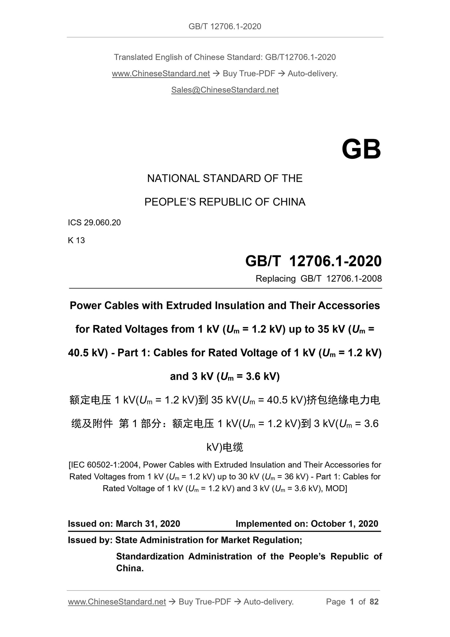
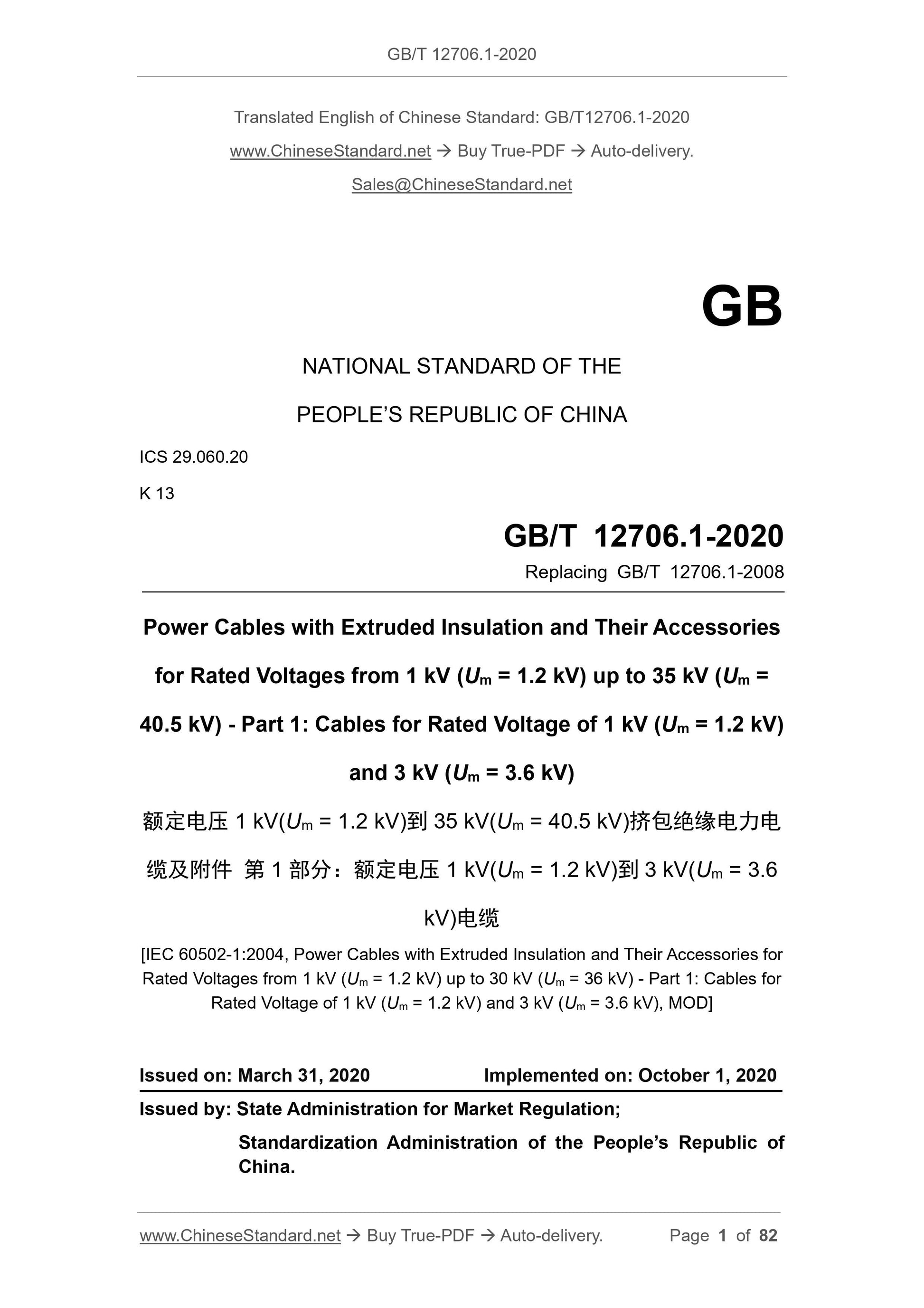
GB/T 12706.1-2020
GB
NATIONAL STANDARD OF THE
PEOPLE’S REPUBLIC OF CHINA
ICS 29.060.20
K 13
Replacing GB/T 12706.1-2008
Power Cables with Extruded Insulation and Their Accessories
for Rated Voltages from 1 kV (Um = 1.2 kV) up to 35 kV (Um =
40.5 kV) - Part 1: Cables for Rated Voltage of 1 kV (Um = 1.2 kV)
and 3 kV (Um = 3.6 kV)
[IEC 60502-1:2004, Power Cables with Extruded Insulation and Their Accessories for
Rated Voltages from 1 kV (Um = 1.2 kV) up to 30 kV (Um = 36 kV) - Part 1: Cables for
Rated Voltage of 1 kV (Um = 1.2 kV) and 3 kV (Um = 3.6 kV), MOD]
ISSUED ON: MARCH 31, 2020
IMPLEMENTED ON: OCTOBER 1, 2020
Issued by: State Administration for Market Regulation;
Standardization Administration of the People’s Republic of
China.
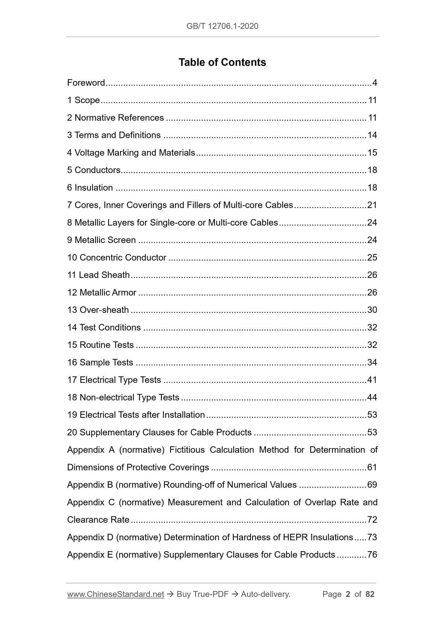
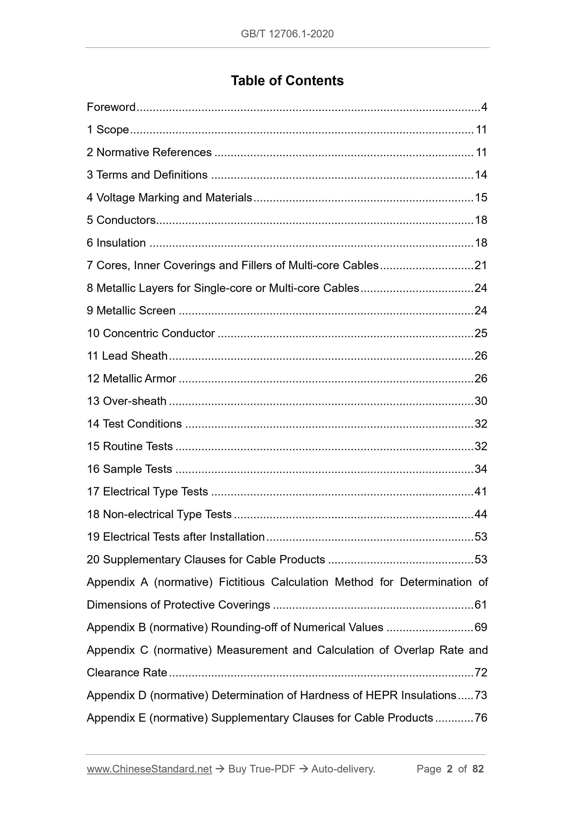
Table of Contents
Foreword ... 4
1 Scope ... 11
2 Normative References ... 11
3 Terms and Definitions ... 14
4 Voltage Marking and Materials ... 15
5 Conductors... 18
6 Insulation ... 18
7 Cores, Inner Coverings and Fillers of Multi-core Cables ... 21
8 Metallic Layers for Single-core or Multi-core Cables ... 24
9 Metallic Screen ... 24
10 Concentric Conductor ... 25
11 Lead Sheath ... 26
12 Metallic Armor ... 26
13 Over-sheath ... 30
14 Test Conditions ... 32
15 Routine Tests ... 32
16 Sample Tests ... 34
17 Electrical Type Tests ... 41
18 Non-electrical Type Tests ... 44
19 Electrical Tests after Installation ... 53
20 Supplementary Clauses for Cable Products ... 53
Appendix A (normative) Fictitious Calculation Method for Determination of
Dimensions of Protective Coverings ... 61
Appendix B (normative) Rounding-off of Numerical Values ... 69
Appendix C (normative) Measurement and Calculation of Overlap Rate and
Clearance Rate ... 72
Appendix D (normative) Determination of Hardness of HEPR Insulations ... 73
Appendix E (normative) Supplementary Clauses for Cable Products ... 76
Bibliography ... 82
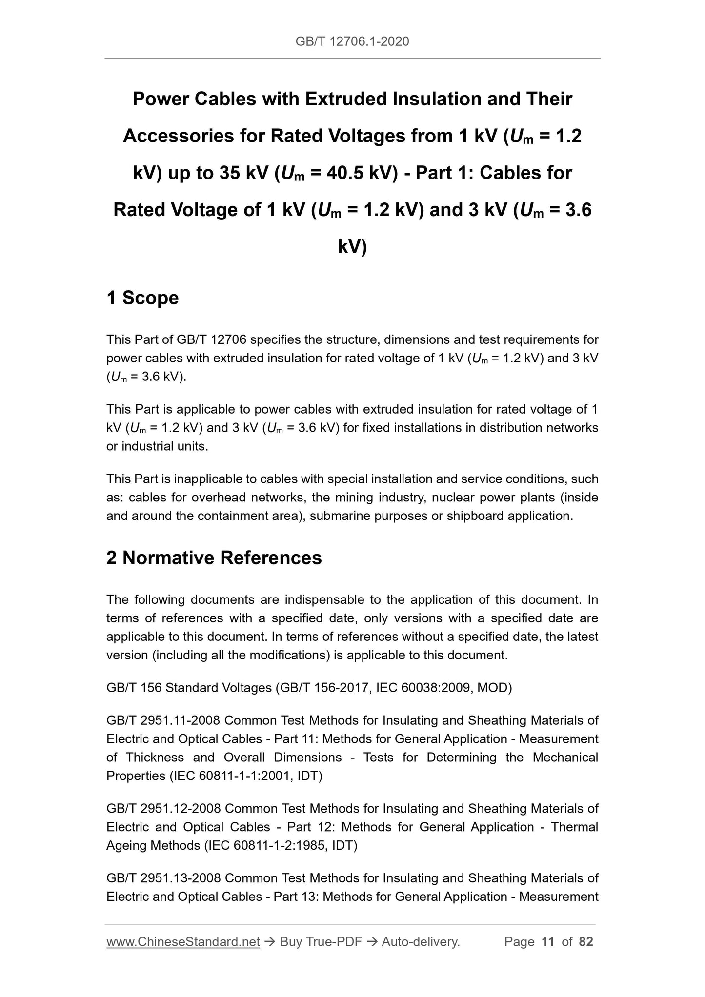
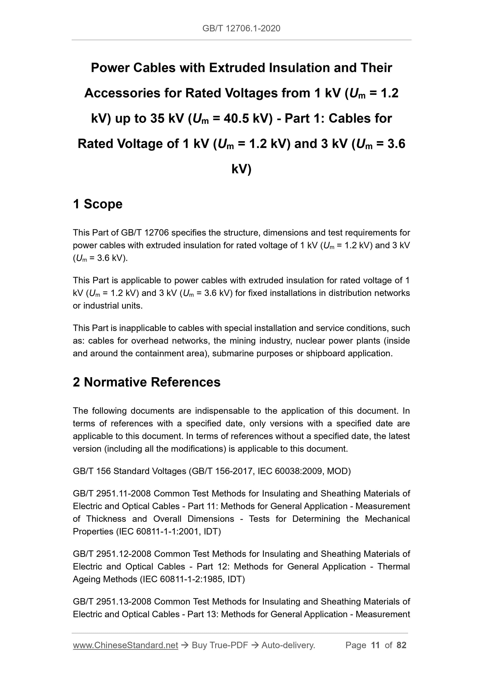
Power Cables with Extruded Insulation and Their
Accessories for Rated Voltages from 1 kV (Um = 1.2
kV) up to 35 kV (Um = 40.5 kV) - Part 1: Cables for
Rated Voltage of 1 kV (Um = 1.2 kV) and 3 kV (Um = 3.6
kV)
1 Scope
This Part of GB/T 12706 specifies the structure, dimensions and test requirements for
power cables with extruded insulation for rated voltage of 1 kV (Um = 1.2 kV) and 3 kV
(Um = 3.6 kV).
This Part is applicable to power cables with extruded insulation for rated voltage of 1
kV (Um = 1.2 kV) and 3 kV (Um = 3.6 kV) for fixed installations in distribution networks
or industrial units.
This Part is inapplicable to cables with special installation and service conditions, such
as: cables for overhead networks, the mining industry, nuclear power plants (inside
and around the containment area), submarine purposes or shipboard application.
2 Normative References
The following documents are indispensable to the application of this document. In
terms of references with a specified date, only versions with a specified date are
applicable to this document. In terms of references without a specified date, the latest
version (including all the modifications) is applicable to this document.
GB/T 156 Standard Voltages (GB/T 156-2017, IEC 60038:2009, MOD)
GB/T 2951.11-2008 Common Test Methods for Insulating and Sheathing Materials of
Electric and Optical Cables - Part 11: Methods for General Application - Measurement
of Thickness and Overall Dimensions - Tests for Determining the Mechanical
Properties (IEC 60811-1-1:2001, IDT)
GB/T 2951.12-2008 Common Test Methods for Insulating and Sheathing Materials of
Electric and Optical Cables - Part 12: Methods for General Application - Thermal
Ageing Methods (IEC 60811-1-2:1985, IDT)
GB/T 2951.13-2008 Common Test Methods for Insulating and Sheathing Materials of
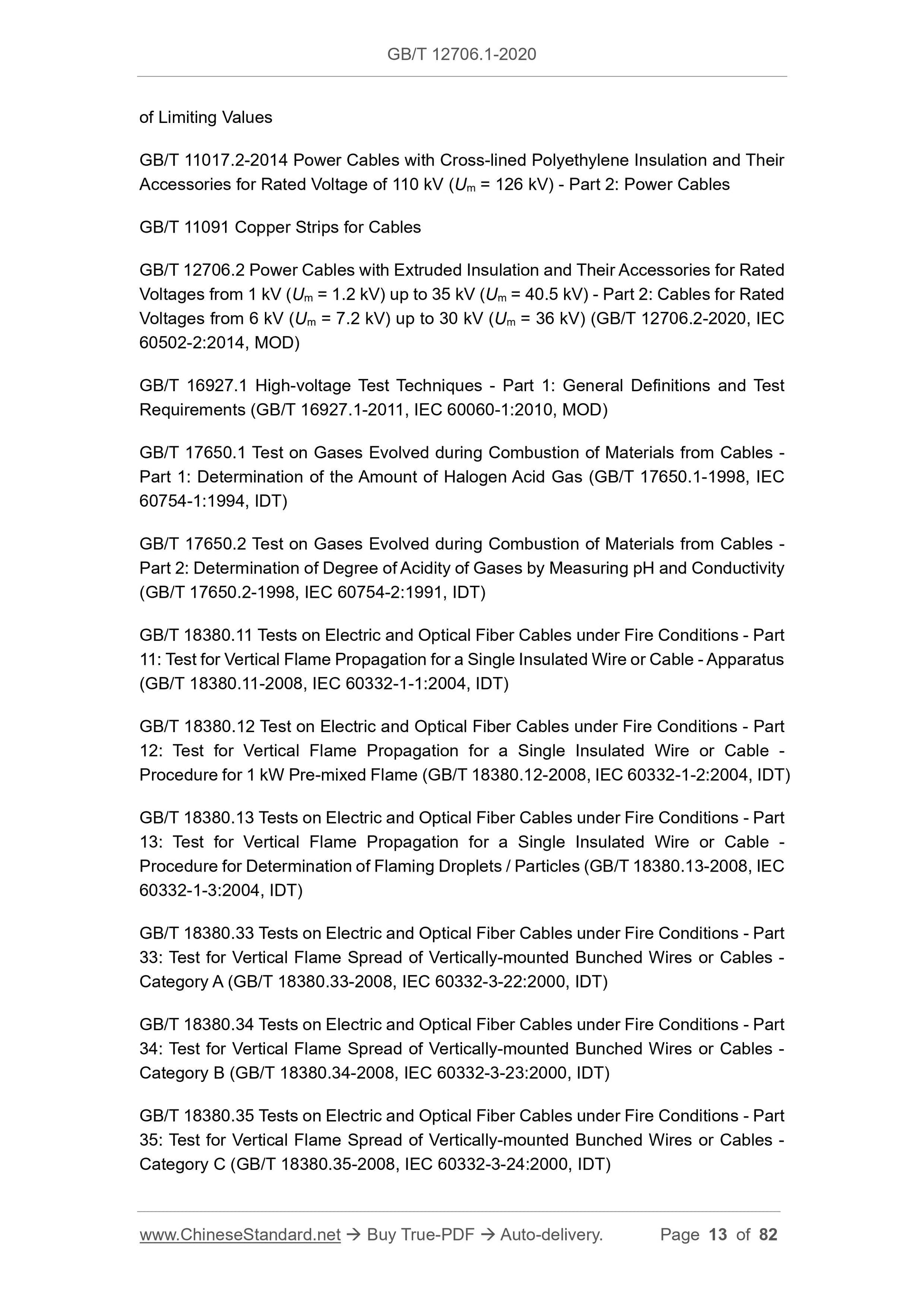
Electric and Optical Cables - Part 13: Methods for General Application - Measurement
of Limiting Values
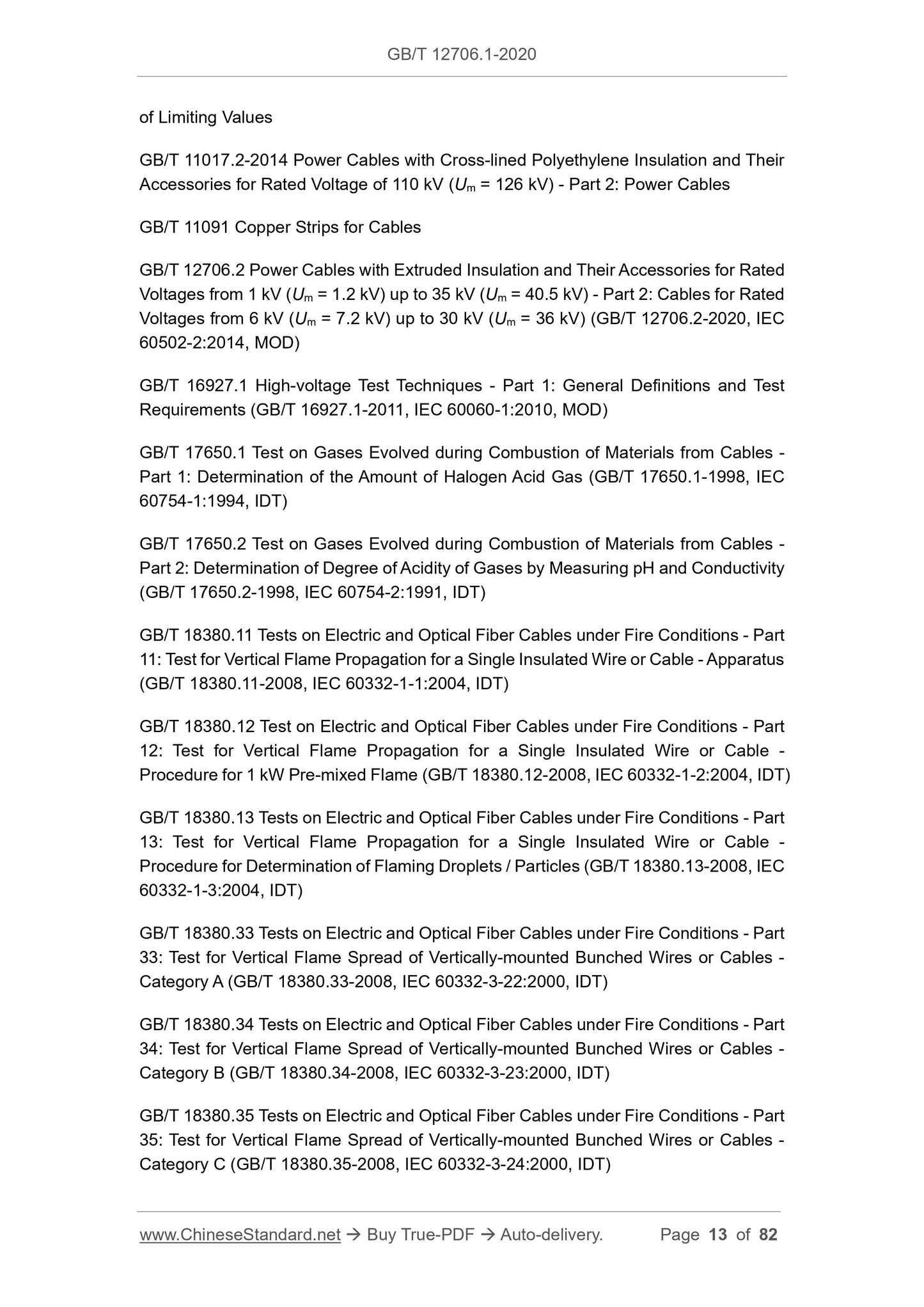
GB/T 11017.2-2014 Power Cables with Cross-lined Polyethylene Insulation and Their
Accessories for Rated Voltage of 110 kV (Um = 126 kV) - Part 2: Power Cables
GB/T 11091 Copper Strips for Cables
GB/T 12706.2 Power Cables with Extruded Insulation and Their Accessories for Rated
Voltages from 1 kV (Um = 1.2 kV) up to 35 kV (Um = 40.5 kV) - Part 2: Cables for Rated
Voltages from 6 kV (Um = 7.2 kV) up to 30 kV (Um = 36 kV) (GB/T 12706.2-2020, IEC
60502-2:2014, MOD)
GB/T 16927.1 High-voltage Test Techniques - Part 1: General Definitions and Test
Requirements (GB/T 16927.1-2011, IEC 60060-1:2010, MOD)
GB/T 17650.1 Test on Gases Evolved during Combustion of Materials from Cables -
Part 1: Determination of the Amount of Halogen Acid Gas (GB/T 17650.1-1998, IEC
60754-1:1994, IDT)
GB/T 17650.2 Test on Gases Evolved during Combustion of Materials from Cables -
Part 2: Determination of Degree of Acidity of Gases by Measuring pH and Conductivity
(GB/T 17650.2-1998, IEC 60754-2:1991, IDT)
GB/T 18380.11 Tests on Electric and Optical Fiber Cables under Fire Conditions - Part
11: Test for Vertical Flame Propagation for a Single Insulated Wire or Cable - Apparatus
(GB/T 18380.11-2008, IEC 60332-1-1:2004, IDT)
GB/T 18380.12 Test on Electric and Optical Fiber Cables under Fire Conditions - Part
12: Test for Vertical Flame Propagation for a Single Insulated Wire or Cable -
Procedure for 1 kW Pre-mixed Flame (GB/T 18380.12-2008, IEC 60332-1-2:2004, IDT)
GB/T 18380.13 Tests on Electric and Optical Fiber Cables under Fire Conditions - Part
13: Test for Vertical Flame Propagation for a Single Insulated Wire or Cable -
Procedure for Determination of Flaming Droplets / Particles (GB/T 18380.13-2008, IEC
60332-1-3:2004, IDT)
GB/T 18380.33 Tests on Electric and Optical Fiber Cables under Fire Conditions - Part
33: Test for Vertical Flame Spread of Vertically-mounted Bunched Wires or Cables -
Category A (GB/T 18380.33-2008, IEC 60332-3-22:2000, IDT)
GB/T 18380.34 Tests on Electric and Optical Fiber Cables under Fire Conditions - Part
34: Test for Vertical Flame Spread of Vertically-mounted Bunched Wires or Cables -
Category B (GB/T 18380.34-2008, IEC 60332-3-23:2000, IDT)
GB/T 18380.35 Tests on Electric and Optical Fiber Cables under Fire Conditions - Part
35: Test for Vertical Flame Spread of Vertically-mounted Bunched Wires or Cables -
Category C (GB/T 18380.35-2008, IEC 60332-3-24:2000, IDT)
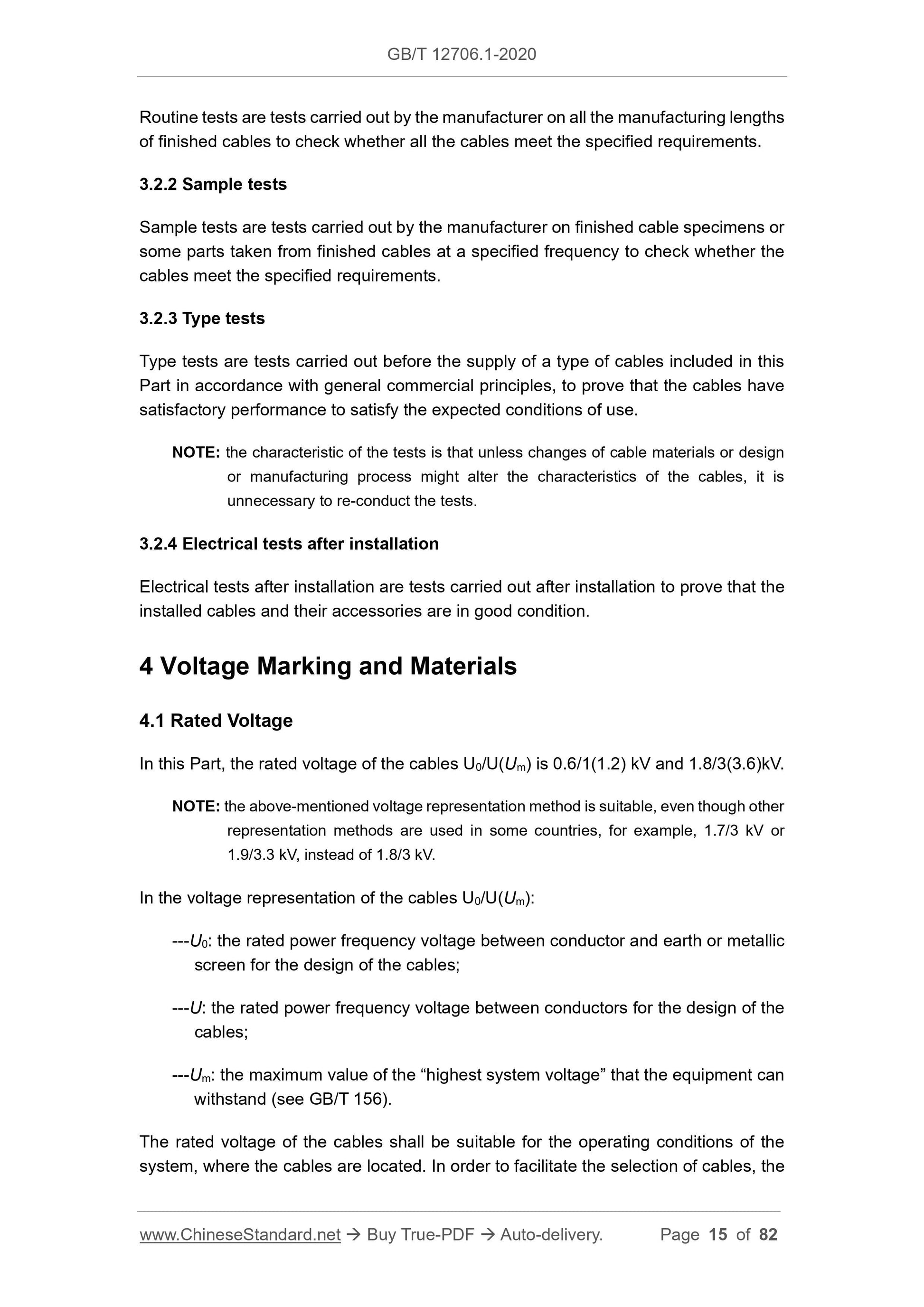
Routine tests are tests carried out by the manufacturer on all the manufacturing lengths
of finished cables to check whether all the cables meet the specified requirements.
3.2.2 Sample tests
Sample tests are tests carried out by the manufacturer on finished cable specimens or
some parts taken from finished cables at a specified frequency to check whether the
cables meet the specified requirements.
3.2.3 Type tests
Type tests are tests carried out before the supply of a type of cables included in this
Part in accordance with general commercial principles, to prove that the cables have
satisfactory performance to satisfy the expected conditions of use.
NOTE: the characteristic of the tests is that unless changes of cable materials or design
or manufacturing process might alter the characteristics of the cables, it is
unnecessary to re-conduct the tests.
3.2.4 Electrical tests after installation
Electrical tests after installation are tests carried out after installation to prove that the
installed cables and their accessories are in good condition.
4 Voltage Marking and Materials
4.1 Rated Voltage
In this Part, the rated voltage of the cables U0/U(Um) is 0.6/1(1.2) kV and 1.8/3(3.6)kV.
NOTE: the above-mentioned voltage representation method is suitable, even though other
representation methods are used in some countries, for example, 1.7/3 kV or
1.9/3.3 kV, instead of 1.8/3 kV.
In the voltage representation of the cables U0/U(Um):
---U0: the rated power frequency voltage between conductor and earth or metallic
screen for the design of the cables;
---U: the rated power frequency voltage between conductors for the design of the
cables;
---Um: the maximum value of the “highest system voltage” that the equipment can
withstand (see GB/T 156).
The rated voltage of the cables shall be suitable for the operating conditions of the
system, where the cables are located. In order to facilitate the selection of cables, the
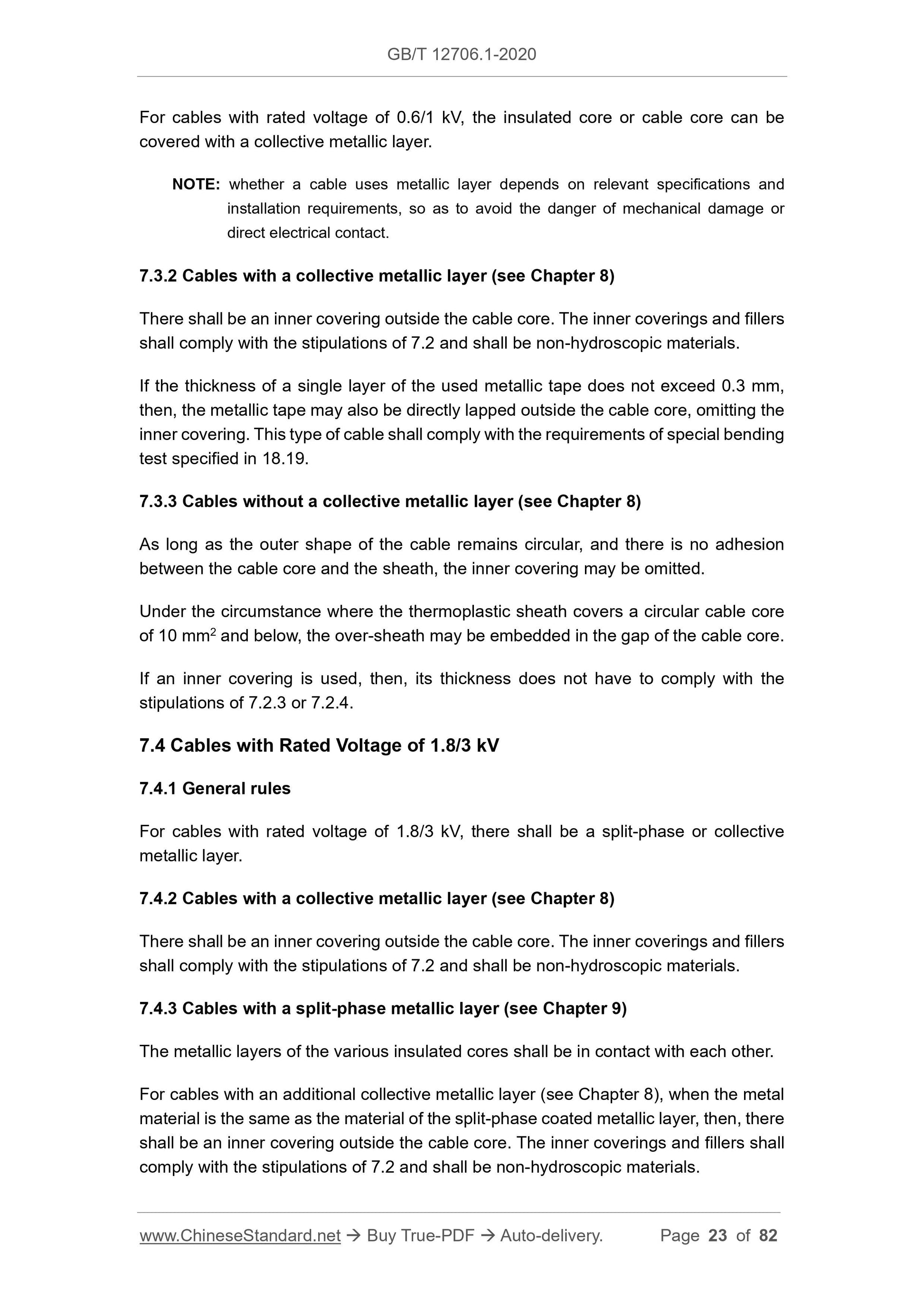
For cables with rated voltage of 0.6/1 kV, the insulated core or cable core can be
covered with a collective metallic layer.
NOTE: whether a cable uses metallic layer depends on relevant specifications and
installation requirements, so as to avoid the danger of mechanical damage or
direct electrical contact.
7.3.2 Cables with a collective metallic layer (see Chapter 8)
There shall be an inner covering outside the cable core. The inner coverings and fillers
shall comply with the stipulations of 7.2 and shall be non-hydroscopic materials.
If the thickness of a single layer of the used metallic tape does not exceed 0.3 mm,
then, the metallic tape may also be directly lapped outside the cable core, omitting the
inner covering. This type of cable shall comply with the requirements of special bending
test specified in 18.19.
7.3.3 Cables without a collective metallic layer (see Chapter 8)
As long as the outer shape of the cable remains circular, and there is no adhesion
between the cable core and the sheath, the inner covering may be omitted.
Under the circumstance where the thermoplastic sheath covers a circular cable core
of 10 mm2 and below, the over-sheath may be embedded in the gap of the cable core.
If an inner covering is used, then, its thickness does not have to comply with the
stipulations of 7.2.3 or 7.2.4.
7.4 Cables with Rated Voltage of 1.8/3 kV
7.4.1 General rules
For cables with rated voltage of 1.8/3 kV, there shall be a split-phase or collective
metallic layer.
7.4.2 Cables with a collective metallic layer (see Chapter 8)
There shall be an inner covering outside the cable core. The inner coverings and fillers
shall comply with the stipulations of 7.2 and shall be non-hydroscopic materials.
7.4.3 Cables with a split-phase metallic layer (see Chapter 9)
The metallic layers of the various insulated cores shall be in contact with each other.
For cables with an additional collective metallic layer (see Chapter 8), when the metal
material is the same as the material of the split-phase coated metallic layer, then, there
shall be an inner covering outside the cable core. The inner coverings and fillers shall
comply with the stipulations of 7.2 and shall be non-hydroscopic materials.
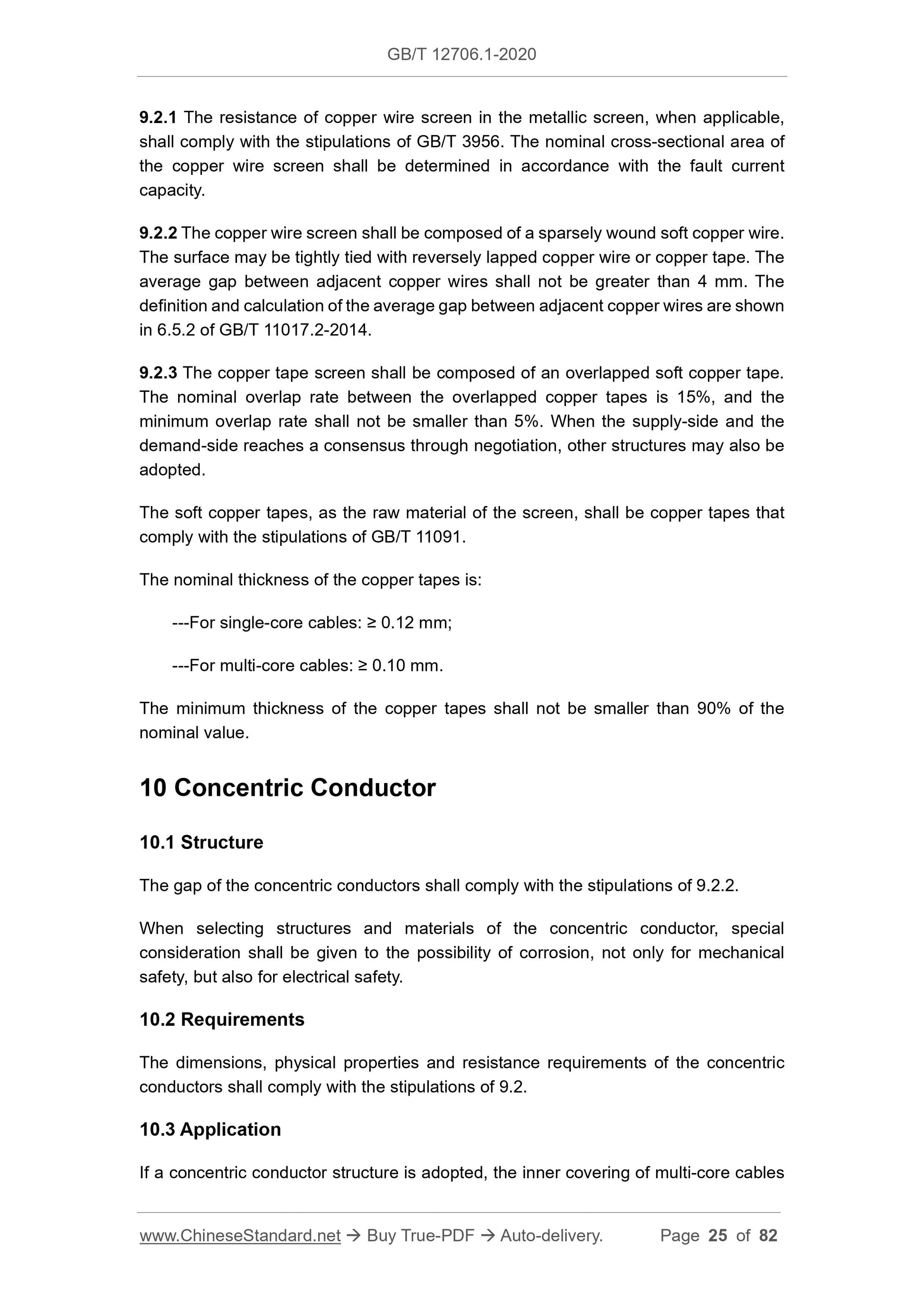
9.2.1 The resistance of copper wire screen in the metallic screen, when applicable,
shall comply with the stipulations of GB/T 3956. The nominal cross-sectional area of
the copper wire screen shall be determined in accordance with the fault current
capacity.
9.2.2 The copper wire screen shall be composed of a sparsely wound soft copper wire.
The surface may be tightly tied with reversely lapped copper wire or copper tape. The
average gap between adjacent copper wires shall not be greater than 4 mm. The
definition and calculation of the average gap between adjacent copper wires are shown
in 6.5.2 of GB/T 11017.2-2014.
9.2.3 The copper tape screen shall be composed of an overlapped soft copper tape.
The nominal overlap rate between the overlapped copper tapes is 15%, and the
minimum overlap rate shall not be smaller than 5%. When the supply-side and the
demand-side reaches a consensus through negotiation, other structures may also be
adopted.
The soft copper tapes, as the raw material of the screen, shall be copper tapes that
comply with the stipulations of GB/T 11091.
The nominal thickness of the copper tapes is:
---For single-core cables: ≥ 0.12 mm;
---For multi-core cables: ≥ 0.10 mm.
The minimum thickness of the copper tapes shall not be smaller than 90% of the
nominal value.
10 Concentric Conductor
10.1 Structure
The gap of the concentric conductors shall comply with the stipulations of 9.2.2.
When selecting structures and materials of the concentric conductor, special
consideration shall be given to the possibility of corrosion, not only for mechanical
safety, but also for electrical safety.
10.2 Requirements
The dimensions, physical properties and resistance requirements of the concentric
conductors shall comply with the stipulations of 9.2.
10.3 Application
If a concentric conductor structure is adopted, the inner covering of multi-core cables
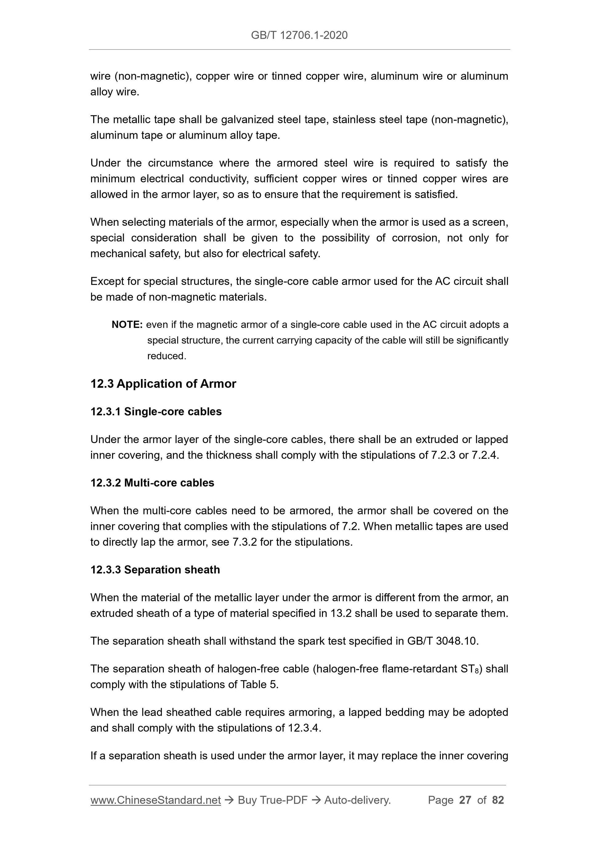
wire (non-magnetic), copper wire or tinned copper wire, aluminum wire or aluminum
alloy wire.
The metallic tape shall be galvanized steel tape, stainless steel tape (non-magnetic),
aluminum tape or aluminum alloy tape.
Under the circumstance where the armored steel wire is required to satisfy the
minimum electrical conductivity, sufficient copper wires or tinned copper wires are
allowed in the armor layer, so as to ensure that the requirement is satisfied.
When selecting materials of the armor, especially when the armor is used as a screen,
special consideration shall be given to the possibility of corrosion, not only for
mechanical safety, but also for electrical safety.
Except for special structures, the single-core cable armor used for the AC circuit shall
be made of non-magnetic materials.
NOTE: even if the magnetic armor of a single-core cable used in the AC circuit adopts a
special structure, the current carrying capacity of the cable will still be significantly
reduced.
12.3 Application of Armor
12.3.1 Single-core cables
Under the armor layer of the single-core cables, there shall be an extruded or lapped
inner covering, and the thickness shall comply with the stipulations of 7.2.3 or 7.2.4.
12.3.2 Multi-core cables
When the multi-core cables need to be armored, the armor shall be covered on the
inner covering that complies with the stipulations of 7.2. When metallic tapes are used
to directly lap the armor, see 7.3.2 for the stipulations.
12.3.3 Separation sheath
When the material of the metallic layer under the armor is ...
Share
