1
/
of
12
www.ChineseStandard.us -- Field Test Asia Pte. Ltd.
GB/T 13564-2022 English PDF (GB/T13564-2022)
GB/T 13564-2022 English PDF (GB/T13564-2022)
Regular price
$350.00
Regular price
Sale price
$350.00
Unit price
/
per
Shipping calculated at checkout.
Couldn't load pickup availability
GB/T 13564-2022: Roller opposite forces type automobile brake tester
Delivery: 9 seconds. Download (& Email) true-PDF + Invoice.
Get Quotation: Click GB/T 13564-2022 (Self-service in 1-minute)
Historical versions (Master-website): GB/T 13564-2022
Preview True-PDF (Reload/Scroll-down if blank)
GB/T 13564-2022
NATIONAL STANDARD OF THE
PEOPLE’S REPUBLIC OF CHINA
ICS 43.180
CCS R 17
Replacing GB/T 13564-2005
Roller Opposite Forces Type Automobile Brake Tester
ISSUED ON: MARCH 09, 2022
IMPLEMENTED ON: OCTOBER 01, 2022
Issued by: State Administration for Market Regulation;
Standardization Administration of the People’s Republic of China.
Table of Contents
Foreword ... 3
1 Scope ... 5
2 Normative References ... 5
3 Terms and Definitions ... 5
4 Classification and Model ... 7
5 Technical Requirements ... 7
6 Test Methods ... 13
7 Inspection Rules ... 26
8 Marking, Packaging, Transportation and Storage ... 27
Bibliography ... 29
Roller Opposite Forces Type Automobile Brake Tester
1 Scope
This Document specifies the requirements for classification and model, technical requirements,
test methods, inspection rules, and marking, packaging, transportation and storage of roller
opposite forces type automobile brake tester.
This Document applies to the design, production, inspection and use of the roller opposite
forces type automobile brake tester; and the roller opposite forces motorcycle brake tester can
use it as a reference.
2 Normative References
The provisions in following documents become the essential provisions of this Document
through reference in this Document. For the dated documents, only the versions with the dates
indicated are applicable to this Document; for the undated documents, only the latest version
(including all the amendments) is applicable to this Document.
GB/T 191 Packaging – Pictorial Marking for Handling of Goods
GB/T 13306 Plates
GB/T 13384 General Specifications for Packing of Mechanical and Electrical Product
JT/T 1279 Axle (Wheel) Weighing Instrument for Motor Vehicle Detection
3 Terms and Definitions
For the purposes of this Document, the following terms and definitions apply.
3.1 Roller opposite forces type automobile brake tester
A device for detecting the braking performance of an automobile by measuring the opposite
force of the wheel braking force acting on the main roller.
3.2 Roller opposite forces type automobile lift loading brake tester
A device for detecting the braking performance of an automobile by measuring the opposite
force of the wheel braking force acting on the main roller, and by using a lifting device to raise
the axle under test to a specified height, increase the static axle load of the axle.
3.3 Main roller
The roller that is driven by the motor and is directly driven to rotate through the deceleration
mechanism.
3.4 Auxiliary roller
The roller that is parallel to the main roller and is driven by the main roller to rotate through a
synchronizing device.
3.5 Resolution of a displaying device
The smallest difference between the displayed indications that the displaying instrument can
effectively identify.
3.6 Third roller
The roller that is independent and located between the main roller and the auxiliary roller, and
is used to detect the linear speed of the wheel under test.
3.7 Rated loading capacity
The maximum axle mass of the automobile under test that is allowed to be carried by the roller
opposite forces type automobile brake tester.
3.8 Slip adhesion coefficient of roller
The ratio of the wheel braking force to the wheel load measured by the roller opposite forces
type automobile brake tester, when the test wheel of the roller adhesion coefficient tester locks
and slips on the busbar on the main roller.
3.9 Idling dynamic zero error
The maximum zero deviation value displayed by the instrument of the roller opposite forces
type automobile brake tester under the no-load stable operation state.
3.10 Differences between indications value
The absolute value of the differences between the indications value of the braking force
measured by the left and right roller groups at the same test point.
3.11 Equate position roller
The position on the roller surface or extension of roller axis that is close to the roller side.
3.12 Slip rate
shall be no greater than 2mm.
5.4.2 The third roller
5.4.2.1 The third roller shall rotate flexibly without sticking.
5.4.2.2 The slip rate when the drive motor automatically stops shall be 25%~35%.
5.4.2.3 The third roller shall be in reliable contact with the wheel under test. When the wheel
under test is braking, the third roller shall not lose contact with the wheel under test due to
jumping.
5.4.3 Displaying device
The digital display shall be stable, with no missing segments or flickering. For the brake tester
used by a single machine, the retention time of the measured data shall be no less than 8s.
5.4.4 Electrical system
5.4.4.1 Electrical system response error
The electrical system shall have the filtering function to eliminate invalid signals such as rack
vibration and electromagnetic interference; and the response error of the electrical system of
the brake tester shall not exceed ±3%.
5.4.4.2 Data sampling
The sampling frequency of brake force shall be no lower than 100Hz.
5.4.4.3 Data processing
Under the condition that the third roller stops and control does not work, the continuous
sampling time of the braking force is no less than 3s. The maximum braking force shall be
screened and displayed in all sampling points collected in the whole process of braking
detection.
5.4.4.4 Safety protection
5.4.4.4.1 The electrical system shall be able to withstand the withstand voltage test of 50Hz,
1.5kV, which lasted for 1min; and shall not appear breakdown, arcing and other phenomena.
5.4.4.4.2 The insulation resistance of the electrical system shall be no less than 5MΩ.
5.4.4.4.3 The electrical system shall be equipped with fuses or circuit breakers according to the
size of the load; the drive motor control shall be provided with overload and phase failure
protection devices.
5.4.4.4.4 The electrical system shall have reliable grounding devices and obvious grounding
signs; and the brake tester shall be reliably grounded during installation and use.
5.4.4.4.5 The electrical system shall be provided with a manual button for emergency stop.
5.5 Special requirements for loading brake tester
5.5.1 Loading device
The loading brake tester shall have a rack lifting device; and can end the lifting action accurately
and reliably at the specified lifting height.
5.5.2 Lifting height error
The allowable error of the lifting height of the loading brake tester is 0mm~5mm.
5.5.3 Lifting height difference between left and right roller groups
When the loading brake tester is lifted to the specified height, the lift height difference between
the left and right roller groups shall be no greater than 2mm.
5.5.4 Lifting stability
5.5.4.1 Under a load of no less than 50% of the rated loading capacity, when the loading brake
tester is lifted to the highest point, the drop in 10 min shall be no greater than 2mm.
5.5.4.2 The front, rear, left and right directions of the lifting rack of loading brake tester shall
be provided with adjustable limit devices.
5.5.4.3 The loading brake tester shall run smoothly when it is lifted and lowered, and there is
no sticking phenomenon.
5.5.5 Weighing Requirements
The axle (wheel) weight gauge installed in combination with the loading brake tester shall meet
the requirements of JT/T 1279.
5.6 Appearance quality
5.6.1 The outer surface of the brake tester shall be smooth and clean, and there shall be no
obvious bruises or scratches; the coating surface shall be uniform and strong in adhesion.
5.6.2 Bolts and nuts shall be surface-treated and connected firmly.
5.6.3 Solder joints of weld assembly shall be flat and uniform; and there shall be no defects
such as welding penetration, cracks, and de-soldering, and the welding slag shall be removed.
5.6.4 The gas circuit and oil circuit of the brake tester shall be well sealed, and there shall be
no leakage.
5.6.5 The electrical components and connectors shall be firmly assembled; the wiring shall be
reasonable and neat; the solder joints shall be smooth, and there shall be no rosin joints.
6.4.2 Idling dynamic zero error
6.4.2.1 When the brake tester is idle, the display instrument is set to zero.
6.4.2.2 Load the left and right force measure sensors of the brake tester roller, respectively; so
that the indication value of the brake tester display instrument is stable at a certain value above
100daN; and the display instrument is set to zero.
6.4.2.3 Start the drive motors of the left and right roller groups; after the rotation speed of the
rollers is stable, read the maximum value of the display instrument left and right braking force
indications deviating from the zero position. Repeat the test three times; and the maximum
deviation from the zero position is the idling dynamic zero error.
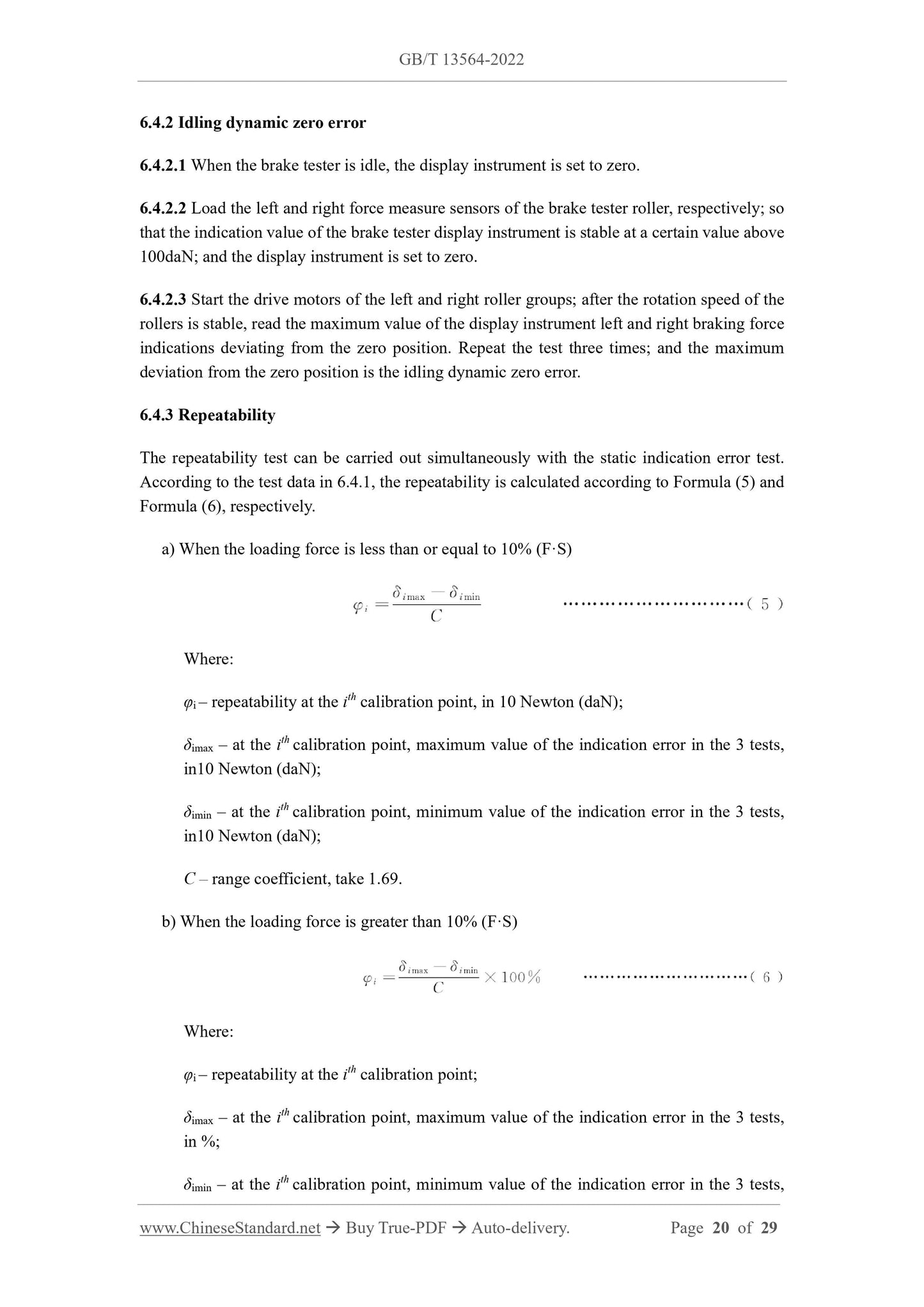
6.4.3 Repeatability
The repeatability test can be carried out simultaneously with the static indication error test.
According to the test data in 6.4.1, the repeatability is calculated according to Formula (5) and
Formula (6), respectively.
a) When the loading force is less than or equal to 10% (F·S)
Where:
φi – repeatability at the ith calibration point, in 10 Newton (daN);
δimax – at the ith calibration point, maximum value of the indication error in the 3 tests,
in10 Newton (daN);
δimin – at the ith calibration point, minimum value of the indication error in the 3 tests,
in10 Newton (daN);
C – range coefficient, take 1.69.
b) When the loading force is greater than 10% (F·S)
Where:
φi – repeatability at the ith calibration point;
δimax – at the ith calibration point, maximum value of the indication error in the 3 tests,
in %;
δimin – at the ith calibration point, minimum value of the indication error in the 3 tests,
third roller; start the drive motor of the brake tester; and after the rotation speed is stable,
measure the current surface linear speed, v0, of the main roller; and take out the backing
wheel.
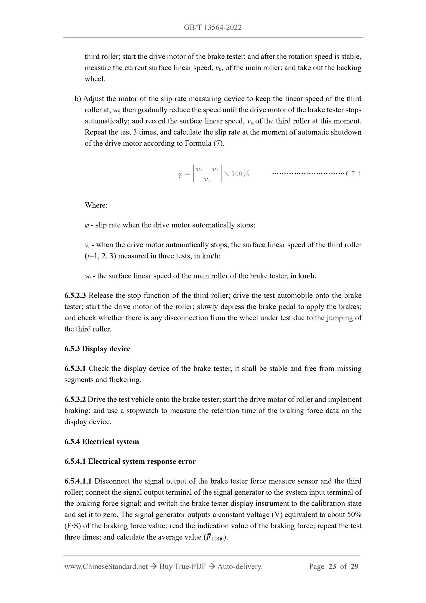
b) Adjust the motor of the slip rate measuring device to keep the linear speed of the third
roller at, v0; then gradually reduce the speed until the drive motor of the brake tester stops
automatically; and record the surface linear speed, vi, of the third roller at this moment.
Repeat the test 3 times, and calculate the slip rate at the moment of automatic shutdown
of the drive motor according to Formula (7).
Where:
φ - slip rate when the drive motor automatically stops;
vi - when the drive motor automatically stops, the surface linear speed of the third roller
(i=1, 2, 3) measured in three tests, in km/h;
v0 - the surface linear speed of the main roller of the brake tester, in km/h.
6.5.2.3 Release the stop function of the third roller; drive the test automobile onto the brake
tester; start the drive motor of the roller; slowly depress the brake pedal to apply the brakes;
and check whether there is any disconnection from the wheel under test due to the jumping of
the third roller.
6.5.3 Display device
6.5.3.1 Check the display device of the brake tester, it shall be stable and free from missing
segments and flickering.
6.5.3.2 Drive the test vehicle onto the brake tester; start the drive motor of roller and implement
braking; and use a stopwatch to measure the retention time of the braking force data on the
display device.
6.5.4 Electrical system
6.5.4.1 Electrical system response error
6.5.4.1.1 Disconnect the signal output of the brake tester force measure sensor and the third
roller; connect the signal output terminal of the signal generator to the system input terminal of
the braking force signal; and switch the brake tester display instrument to the calibration state
and set it to zero. The signal generator outputs a constant voltage (V) equivalent to about 50%
(F·S) of the braking force value; read the indication value of the braking force; repeat the test
three times; and calculate the average value ( L(R)0).
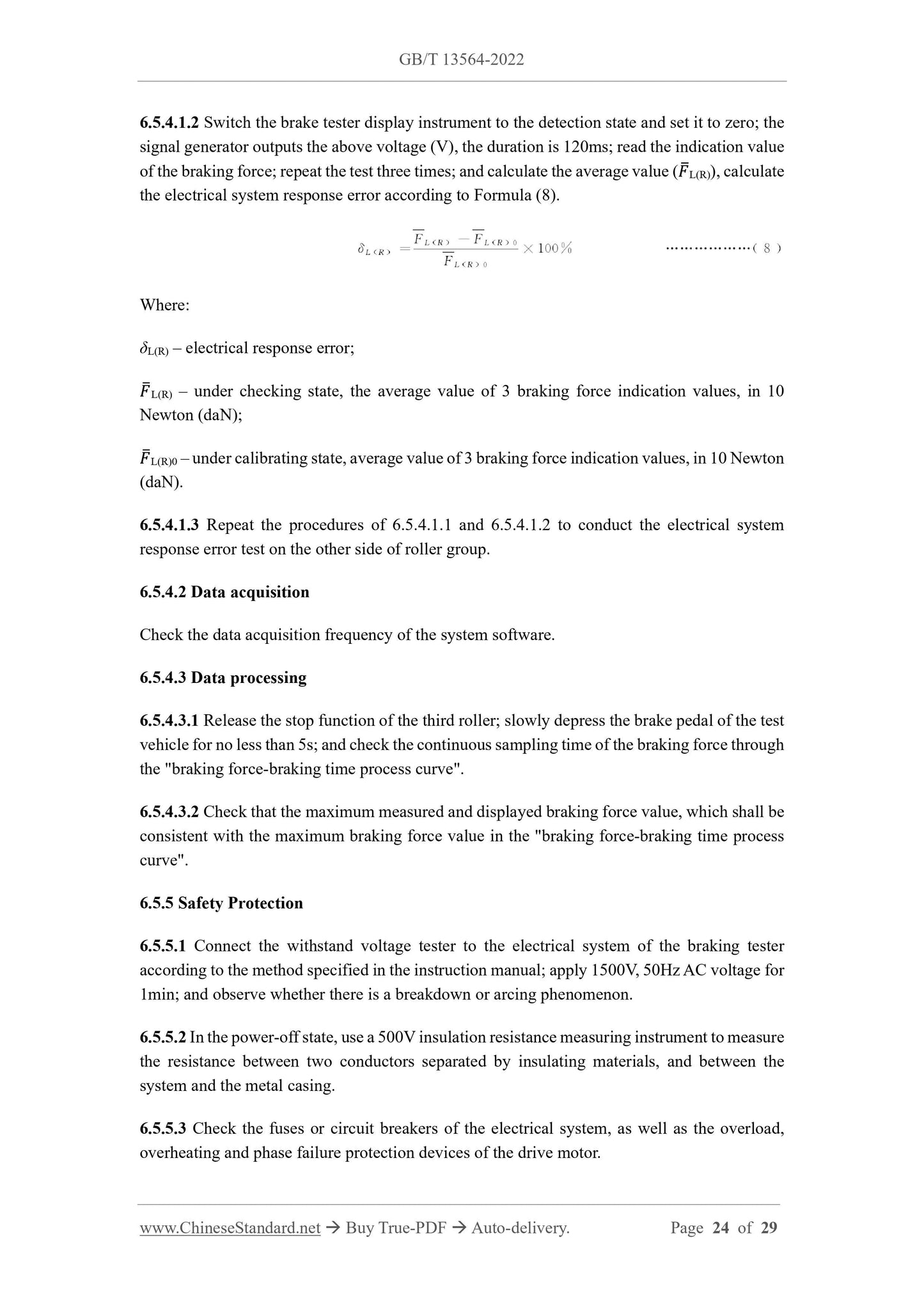
6.5.4.1.2 Switch the brake tester display instrument to the detection state and set it to zero; the
signal generator outputs the above voltage (V), the duration is 120ms; read the indication value
of the braking force; repeat the test three times; and calculate the average value ( L(R)), calculate
the electrical system response error according to Formula (8).
Where:
δL(R) – electrical response error;
L(R) – under checking state, the average value of 3 braking force indication values, in 10
Newton (daN);
L(R)0 – under calibrating state, average value of 3 braking force indication values, in 10 Newton
(daN).
6.5.4.1.3 Repeat the procedures of 6.5.4.1.1 and 6.5.4.1.2 to conduct the electrical system
response error test on the other side of roller group.
6.5.4.2 Data acquisition
Check the data acquisition frequency of the system software.
6.5.4.3 Data processing
6.5.4.3.1 Release the stop function of the third roller; slowly depress the brake pedal of the test
vehicle for no less than 5s; and check the continuous sampling time of the braking force through
the "braking force-braking time process curve".
6.5.4.3.2 Check that the maximum measured and displayed braking force value, which shall be
consistent with the maximum braking force value in the "braking force-braking time process
curve".
6.5.5 Safety Protection
6.5.5.1 Connect the withstand voltage tester to the electrical system of the braking tester
according to the method specified in the instruction manual; apply 1500V, 50Hz AC voltage for
1min; and observe whether there is a breakdown or arcing phenomenon.
6.5.5.2 In the power-off state, use a 500V insulation resistance measuring instrument to measure
the resistance between two conductors separated by insulating materials, and between the
system and the metal casing.
6.5.5.3 Check the fuses or circuit breakers of the electrical system, as well as the overload,
overheating and phase failure protection devices of the drive motor.
6.5.5.4 Check the grounding devices and markings of the electrical system.
6.5.5.5 Check the manual button for emergency stop ...
Delivery: 9 seconds. Download (& Email) true-PDF + Invoice.
Get Quotation: Click GB/T 13564-2022 (Self-service in 1-minute)
Historical versions (Master-website): GB/T 13564-2022
Preview True-PDF (Reload/Scroll-down if blank)
GB/T 13564-2022
NATIONAL STANDARD OF THE
PEOPLE’S REPUBLIC OF CHINA
ICS 43.180
CCS R 17
Replacing GB/T 13564-2005
Roller Opposite Forces Type Automobile Brake Tester
ISSUED ON: MARCH 09, 2022
IMPLEMENTED ON: OCTOBER 01, 2022
Issued by: State Administration for Market Regulation;
Standardization Administration of the People’s Republic of China.
Table of Contents
Foreword ... 3
1 Scope ... 5
2 Normative References ... 5
3 Terms and Definitions ... 5
4 Classification and Model ... 7
5 Technical Requirements ... 7
6 Test Methods ... 13
7 Inspection Rules ... 26
8 Marking, Packaging, Transportation and Storage ... 27
Bibliography ... 29
Roller Opposite Forces Type Automobile Brake Tester
1 Scope
This Document specifies the requirements for classification and model, technical requirements,
test methods, inspection rules, and marking, packaging, transportation and storage of roller
opposite forces type automobile brake tester.
This Document applies to the design, production, inspection and use of the roller opposite
forces type automobile brake tester; and the roller opposite forces motorcycle brake tester can
use it as a reference.
2 Normative References
The provisions in following documents become the essential provisions of this Document
through reference in this Document. For the dated documents, only the versions with the dates
indicated are applicable to this Document; for the undated documents, only the latest version
(including all the amendments) is applicable to this Document.
GB/T 191 Packaging – Pictorial Marking for Handling of Goods
GB/T 13306 Plates
GB/T 13384 General Specifications for Packing of Mechanical and Electrical Product
JT/T 1279 Axle (Wheel) Weighing Instrument for Motor Vehicle Detection
3 Terms and Definitions
For the purposes of this Document, the following terms and definitions apply.
3.1 Roller opposite forces type automobile brake tester
A device for detecting the braking performance of an automobile by measuring the opposite
force of the wheel braking force acting on the main roller.
3.2 Roller opposite forces type automobile lift loading brake tester
A device for detecting the braking performance of an automobile by measuring the opposite
force of the wheel braking force acting on the main roller, and by using a lifting device to raise
the axle under test to a specified height, increase the static axle load of the axle.
3.3 Main roller
The roller that is driven by the motor and is directly driven to rotate through the deceleration
mechanism.
3.4 Auxiliary roller
The roller that is parallel to the main roller and is driven by the main roller to rotate through a
synchronizing device.
3.5 Resolution of a displaying device
The smallest difference between the displayed indications that the displaying instrument can
effectively identify.
3.6 Third roller
The roller that is independent and located between the main roller and the auxiliary roller, and
is used to detect the linear speed of the wheel under test.
3.7 Rated loading capacity
The maximum axle mass of the automobile under test that is allowed to be carried by the roller
opposite forces type automobile brake tester.
3.8 Slip adhesion coefficient of roller
The ratio of the wheel braking force to the wheel load measured by the roller opposite forces
type automobile brake tester, when the test wheel of the roller adhesion coefficient tester locks
and slips on the busbar on the main roller.
3.9 Idling dynamic zero error
The maximum zero deviation value displayed by the instrument of the roller opposite forces
type automobile brake tester under the no-load stable operation state.
3.10 Differences between indications value
The absolute value of the differences between the indications value of the braking force
measured by the left and right roller groups at the same test point.
3.11 Equate position roller
The position on the roller surface or extension of roller axis that is close to the roller side.
3.12 Slip rate
shall be no greater than 2mm.
5.4.2 The third roller
5.4.2.1 The third roller shall rotate flexibly without sticking.
5.4.2.2 The slip rate when the drive motor automatically stops shall be 25%~35%.
5.4.2.3 The third roller shall be in reliable contact with the wheel under test. When the wheel
under test is braking, the third roller shall not lose contact with the wheel under test due to
jumping.
5.4.3 Displaying device
The digital display shall be stable, with no missing segments or flickering. For the brake tester
used by a single machine, the retention time of the measured data shall be no less than 8s.
5.4.4 Electrical system
5.4.4.1 Electrical system response error
The electrical system shall have the filtering function to eliminate invalid signals such as rack
vibration and electromagnetic interference; and the response error of the electrical system of
the brake tester shall not exceed ±3%.
5.4.4.2 Data sampling
The sampling frequency of brake force shall be no lower than 100Hz.
5.4.4.3 Data processing
Under the condition that the third roller stops and control does not work, the continuous
sampling time of the braking force is no less than 3s. The maximum braking force shall be
screened and displayed in all sampling points collected in the whole process of braking
detection.
5.4.4.4 Safety protection
5.4.4.4.1 The electrical system shall be able to withstand the withstand voltage test of 50Hz,
1.5kV, which lasted for 1min; and shall not appear breakdown, arcing and other phenomena.
5.4.4.4.2 The insulation resistance of the electrical system shall be no less than 5MΩ.
5.4.4.4.3 The electrical system shall be equipped with fuses or circuit breakers according to the
size of the load; the drive motor control shall be provided with overload and phase failure
protection devices.
5.4.4.4.4 The electrical system shall have reliable grounding devices and obvious grounding
signs; and the brake tester shall be reliably grounded during installation and use.
5.4.4.4.5 The electrical system shall be provided with a manual button for emergency stop.
5.5 Special requirements for loading brake tester
5.5.1 Loading device
The loading brake tester shall have a rack lifting device; and can end the lifting action accurately
and reliably at the specified lifting height.
5.5.2 Lifting height error
The allowable error of the lifting height of the loading brake tester is 0mm~5mm.
5.5.3 Lifting height difference between left and right roller groups
When the loading brake tester is lifted to the specified height, the lift height difference between
the left and right roller groups shall be no greater than 2mm.
5.5.4 Lifting stability
5.5.4.1 Under a load of no less than 50% of the rated loading capacity, when the loading brake
tester is lifted to the highest point, the drop in 10 min shall be no greater than 2mm.
5.5.4.2 The front, rear, left and right directions of the lifting rack of loading brake tester shall
be provided with adjustable limit devices.
5.5.4.3 The loading brake tester shall run smoothly when it is lifted and lowered, and there is
no sticking phenomenon.
5.5.5 Weighing Requirements
The axle (wheel) weight gauge installed in combination with the loading brake tester shall meet
the requirements of JT/T 1279.
5.6 Appearance quality
5.6.1 The outer surface of the brake tester shall be smooth and clean, and there shall be no
obvious bruises or scratches; the coating surface shall be uniform and strong in adhesion.
5.6.2 Bolts and nuts shall be surface-treated and connected firmly.
5.6.3 Solder joints of weld assembly shall be flat and uniform; and there shall be no defects
such as welding penetration, cracks, and de-soldering, and the welding slag shall be removed.
5.6.4 The gas circuit and oil circuit of the brake tester shall be well sealed, and there shall be
no leakage.
5.6.5 The electrical components and connectors shall be firmly assembled; the wiring shall be
reasonable and neat; the solder joints shall be smooth, and there shall be no rosin joints.
6.4.2 Idling dynamic zero error
6.4.2.1 When the brake tester is idle, the display instrument is set to zero.
6.4.2.2 Load the left and right force measure sensors of the brake tester roller, respectively; so
that the indication value of the brake tester display instrument is stable at a certain value above
100daN; and the display instrument is set to zero.
6.4.2.3 Start the drive motors of the left and right roller groups; after the rotation speed of the
rollers is stable, read the maximum value of the display instrument left and right braking force
indications deviating from the zero position. Repeat the test three times; and the maximum
deviation from the zero position is the idling dynamic zero error.
6.4.3 Repeatability
The repeatability test can be carried out simultaneously with the static indication error test.
According to the test data in 6.4.1, the repeatability is calculated according to Formula (5) and
Formula (6), respectively.
a) When the loading force is less than or equal to 10% (F·S)
Where:
φi – repeatability at the ith calibration point, in 10 Newton (daN);
δimax – at the ith calibration point, maximum value of the indication error in the 3 tests,
in10 Newton (daN);
δimin – at the ith calibration point, minimum value of the indication error in the 3 tests,
in10 Newton (daN);
C – range coefficient, take 1.69.
b) When the loading force is greater than 10% (F·S)
Where:
φi – repeatability at the ith calibration point;
δimax – at the ith calibration point, maximum value of the indication error in the 3 tests,
in %;
δimin – at the ith calibration point, minimum value of the indication error in the 3 tests,
third roller; start the drive motor of the brake tester; and after the rotation speed is stable,
measure the current surface linear speed, v0, of the main roller; and take out the backing
wheel.
b) Adjust the motor of the slip rate measuring device to keep the linear speed of the third
roller at, v0; then gradually reduce the speed until the drive motor of the brake tester stops
automatically; and record the surface linear speed, vi, of the third roller at this moment.
Repeat the test 3 times, and calculate the slip rate at the moment of automatic shutdown
of the drive motor according to Formula (7).
Where:
φ - slip rate when the drive motor automatically stops;
vi - when the drive motor automatically stops, the surface linear speed of the third roller
(i=1, 2, 3) measured in three tests, in km/h;
v0 - the surface linear speed of the main roller of the brake tester, in km/h.
6.5.2.3 Release the stop function of the third roller; drive the test automobile onto the brake
tester; start the drive motor of the roller; slowly depress the brake pedal to apply the brakes;
and check whether there is any disconnection from the wheel under test due to the jumping of
the third roller.
6.5.3 Display device
6.5.3.1 Check the display device of the brake tester, it shall be stable and free from missing
segments and flickering.
6.5.3.2 Drive the test vehicle onto the brake tester; start the drive motor of roller and implement
braking; and use a stopwatch to measure the retention time of the braking force data on the
display device.
6.5.4 Electrical system
6.5.4.1 Electrical system response error
6.5.4.1.1 Disconnect the signal output of the brake tester force measure sensor and the third
roller; connect the signal output terminal of the signal generator to the system input terminal of
the braking force signal; and switch the brake tester display instrument to the calibration state
and set it to zero. The signal generator outputs a constant voltage (V) equivalent to about 50%
(F·S) of the braking force value; read the indication value of the braking force; repeat the test
three times; and calculate the average value ( L(R)0).
6.5.4.1.2 Switch the brake tester display instrument to the detection state and set it to zero; the
signal generator outputs the above voltage (V), the duration is 120ms; read the indication value
of the braking force; repeat the test three times; and calculate the average value ( L(R)), calculate
the electrical system response error according to Formula (8).
Where:
δL(R) – electrical response error;
L(R) – under checking state, the average value of 3 braking force indication values, in 10
Newton (daN);
L(R)0 – under calibrating state, average value of 3 braking force indication values, in 10 Newton
(daN).
6.5.4.1.3 Repeat the procedures of 6.5.4.1.1 and 6.5.4.1.2 to conduct the electrical system
response error test on the other side of roller group.
6.5.4.2 Data acquisition
Check the data acquisition frequency of the system software.
6.5.4.3 Data processing
6.5.4.3.1 Release the stop function of the third roller; slowly depress the brake pedal of the test
vehicle for no less than 5s; and check the continuous sampling time of the braking force through
the "braking force-braking time process curve".
6.5.4.3.2 Check that the maximum measured and displayed braking force value, which shall be
consistent with the maximum braking force value in the "braking force-braking time process
curve".
6.5.5 Safety Protection
6.5.5.1 Connect the withstand voltage tester to the electrical system of the braking tester
according to the method specified in the instruction manual; apply 1500V, 50Hz AC voltage for
1min; and observe whether there is a breakdown or arcing phenomenon.
6.5.5.2 In the power-off state, use a 500V insulation resistance measuring instrument to measure
the resistance between two conductors separated by insulating materials, and between the
system and the metal casing.
6.5.5.3 Check the fuses or circuit breakers of the electrical system, as well as the overload,
overheating and phase failure protection devices of the drive motor.
6.5.5.4 Check the grounding devices and markings of the electrical system.
6.5.5.5 Check the manual button for emergency stop ...
Share