


1
/
of
12
PayPal, credit cards. Download editable-PDF and invoice in 1 second!
GB/T 13752-1992 English PDF (GBT13752-1992)
GB/T 13752-1992 English PDF (GBT13752-1992)
Regular price
$305.00 USD
Regular price
Sale price
$305.00 USD
Unit price
/
per
Shipping calculated at checkout.
Couldn't load pickup availability
Delivery: 3 seconds. Download true-PDF + Invoice.
Get QUOTATION in 1-minute: Click GB/T 13752-1992
Historical versions: GB/T 13752-1992
Preview True-PDF (Reload/Scroll if blank)
GB/T 13752-1992: Design rules for tower cranes
GB/T 13752-92
GB
NATIONAL STANDARD OF THE
PEOPLE’S REPUBLIC OF CHINA
UDC 621.873.001.63
P 97
Design rules for tower cranes
ISSUED ON. NOVEMBER 5, 1992
IMPLEMENTED ON. MAY 1, 1993
Issued by. General Administration of Quality Supervision, Inspection and
Quarantine of the People’s Republic of China
3. No action is required - Full-copy of this standard will be automatically and
immediately delivered to your EMAIL address in 0~60 minutes.
Table of Contents
1 Subject content and scope of application ... 4
2 Normative references ... 4
3 Symbols and codes ... 5
4 General ... 8
5 Structure ... 27
6 Mechanism ... 54
7 Electric ... 79
Annex A (Supplement) Numerical table data for the stability calculation of the
structural members subjected to axial compression and the
bending structural members ... 90
Annex B (Supplement) Table for the fatigue strength calculation of the
structures ... 95
Annex C (Reference) Examples for the working levels of the tower cranes . 100
Annex D (Reference) Estimation method of the hoisting impact factor 1 ... 101
Annex E (Reference) Load generated by the acceleration (deceleration) of
the transmission mechanism ... 103
Annex F (Reference) Selection of the rail and wheel combination ... 107
Annex G (Reference) Determination of the axial force FN ... 108
Annex H (Reference) Calculated length factor μ ... 110
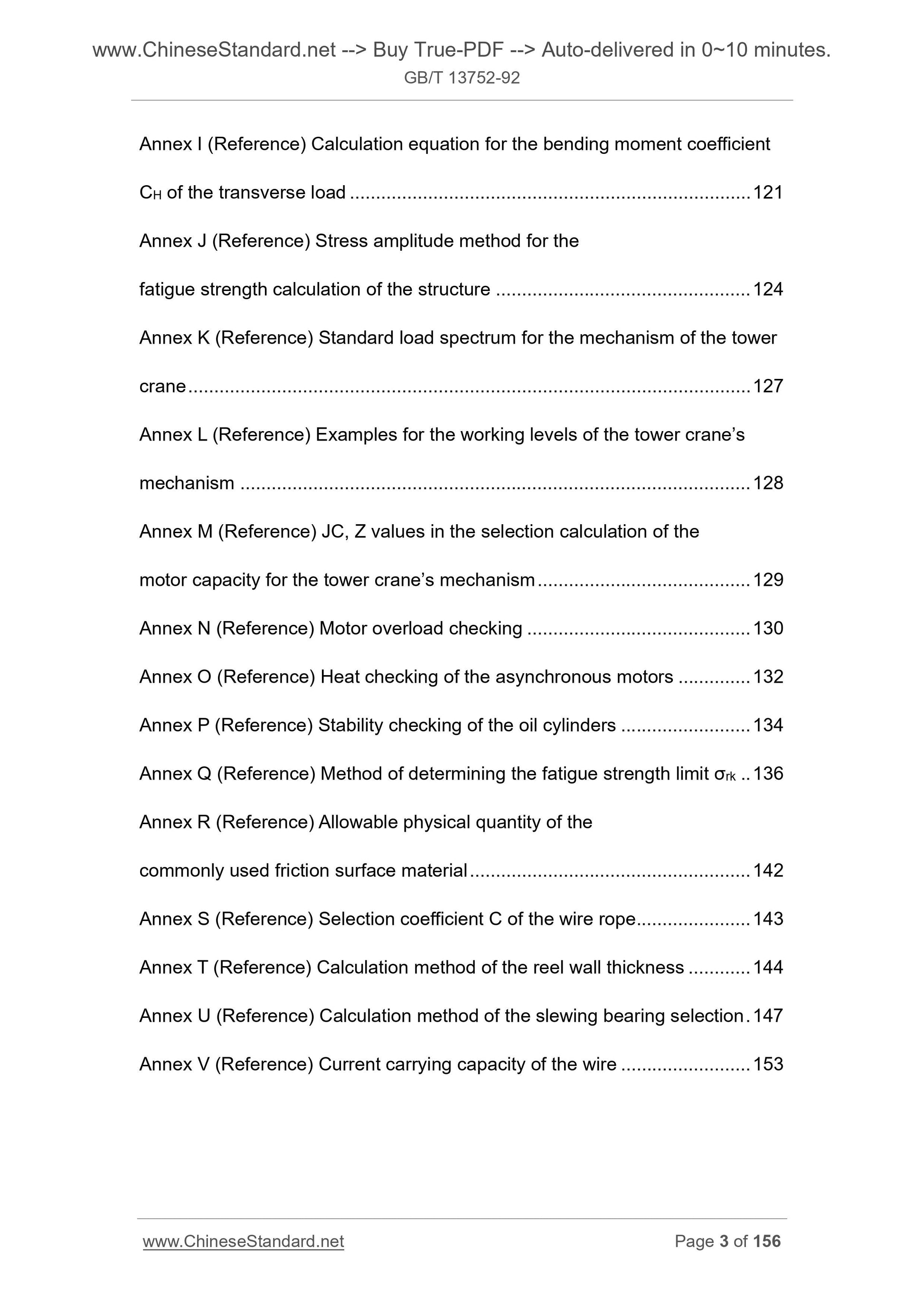
Annex I (Reference) Calculation equation for the bending moment coefficient
CH of the transverse load ... 121
Annex J (Reference) Stress amplitude method for the
fatigue strength calculation of the structure ... 124
Annex K (Reference) Standard load spectrum for the mechanism of the tower
crane ... 127
Annex L (Reference) Examples for the working levels of the tower crane’s
mechanism ... 128
Annex M (Reference) JC, Z values in the selection calculation of the
motor capacity for the tower crane’s mechanism ... 129
Annex N (Reference) Motor overload checking ... 130
Annex O (Reference) Heat checking of the asynchronous motors ... 132
Annex P (Reference) Stability checking of the oil cylinders ... 134
Annex Q (Reference) Method of determining the fatigue strength limit σrk .. 136
Annex R (Reference) Allowable physical quantity of the
commonly used friction surface material ... 142
Annex S (Reference) Selection coefficient C of the wire rope ... 143
Annex T (Reference) Calculation method of the reel wall thickness ... 144
Annex U (Reference) Calculation method of the slewing bearing selection . 147
Annex V (Reference) Current carrying capacity of the wire ... 153
Design rules for tower cranes
1 Subject content and scope of application
This Standard specifies the basic criteria and calculation methods that the
design calculation for tower cranes should follow. All other calculation methods
that are proved to be correct and reliable by theory and practice can also be
used.
This Standard is applicable to various types of power-driven tower cranes for
various uses.
This Standard is not applicable to the tower cranes converted by auto, tyre and
crawler cranes.
2 Normative references
GB 699 Quality carbon structural steels - Technical conditions
GB 700 Carbon structural steels
GB 755 Rotating electrical machines - General technical requirements
GB 985 Basic forms and sizes of weld grooves for gas welding, manual arc
welding and gas-shielded arc welding
GB 986 Basic forms and sizes of weld grooves for submerged arc welding
GB 998 Basic testing method of low voltage apparatus
GB 1591 Low alloy structural steels
GB 10051.1 Lifting hooks - Mechanical properties, lifting capacities, stresses
and materials
GB 1231 Specifications of high strength bolts with large hexagon head, large
hexagon nuts, plain washers for steel structure
GB 1300 Steel wires for welding
GB 3077 Alloy structure steel - Technical requirements
GB 3098.1 Mechanical properties of fasteners - Bolts, screws and studs
GB 3323 Methods for radiographic inspection and classification of
radiographs for fusion welded butt joints in steel
GB 3632 Sets of torshear type high strength bolt hexagon nut and plain
washer for steel structures
GB 3811 Design rules for cranes
GB 5117 Carbon steel covered electrodes
GB 5118 Low alloy steel electrodes
GB 5144 Safety rules for construction tower cranes
GB 10054 Builder’s hoist - Specification
GB 10055 Safety code for builder’s hoist
GB 11352 Carbon steel castings for general engineering purpose
JJ 3 Design rules for construction winches
JJ 12.1 Specification for welding quality of construction machinery
TJ 7 Code for design of industrial and civil building foundation
JJ 40 Fixed fill fluid coupling for tower cranes
JJ 75 Lifting equipment - Design requirements of the hook anti-off pawl
3 Symbols and codes
3.1 Loads
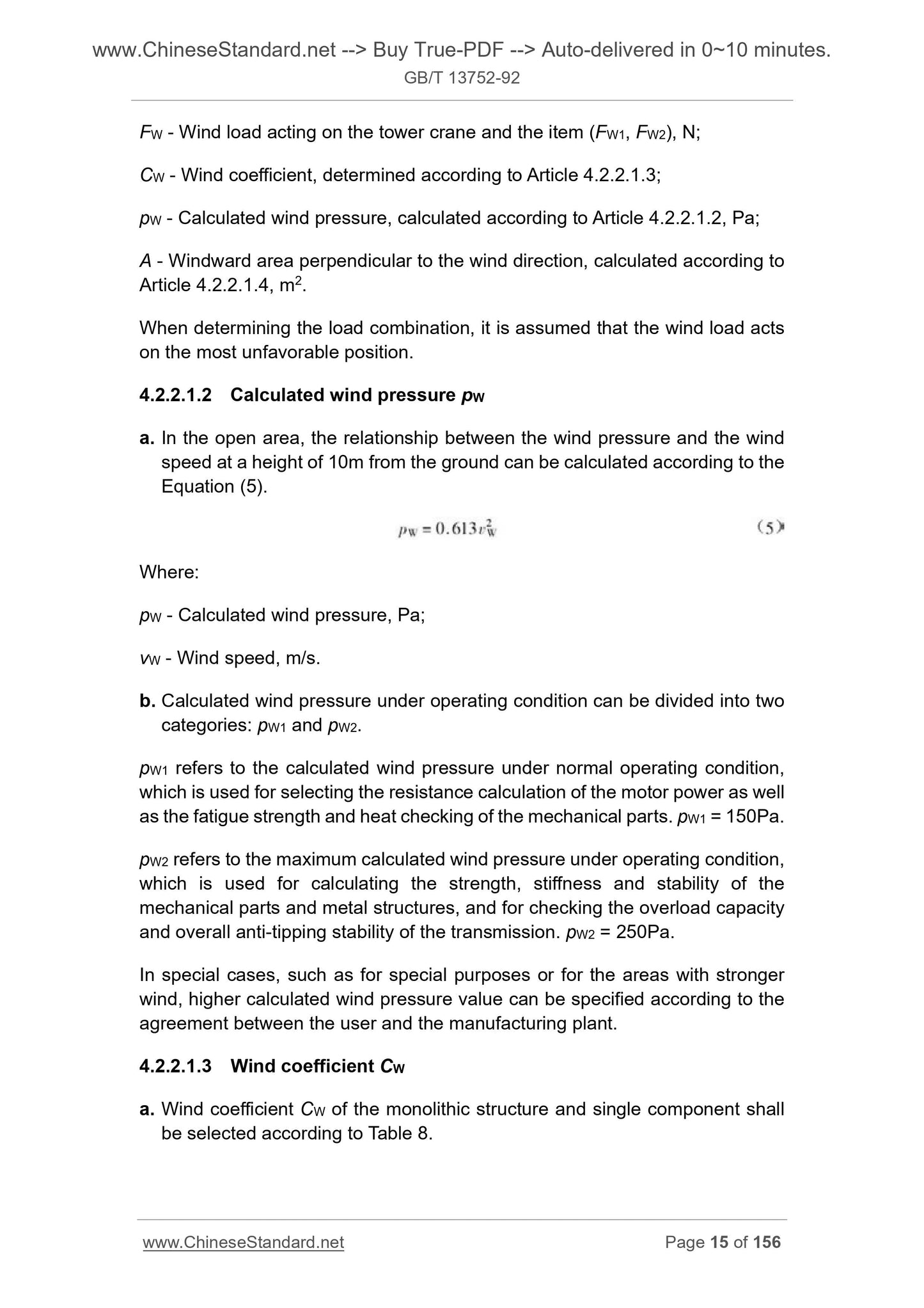
F - Concentrated load, force;
p - Pressure;
M - Bending moment, moment;
T - Torque.
3.2 Limit values for checking
σ - Calculated tensile and compressive stresses;
[σ] - Allowable stress of the materials;
σs - Yield point of the materials;
σb - Tensile strength of the materials;
σ0.2 - Test stress when the residual strain of the standard tensile test for
materials is up to 0.2%;
τ - Calculated shear stress;
[τ] - Allowable shear stress of the materials;
σrk - Fatigue strength limit;
E - Elastic modulus of the materials;
[λ] - Allowable slenderness ratio of the structural members;
λ - Slenderness ratio of the structural members;
σs - Maximum calculated tensile and compressive stress amplitudes;
τa - Maximum calculated shear stress amplitude;
[σa] - Allowable tensile and compressive fatigue stress amplitudes;
[τa] - Allowable shear fatigue stress amplitude.
3.3 Geometric parameters
l, L - Length, distance;
h - Height;
D, d - Diameter;
R, r - Radius;
b - Width;
e - Eccentricity;
Ia - Cross-sectional moment of inertia;
J - Moment of inertia;
W - Section bending modulus of the structural members;
A - Windward area of the structure, cross-sectional area of the structural
members;
P - Thread pitch, rope groove pitch;
δ - Thickness;
ᇞ - Displacement;
θ - Angle;
V - Volume.
3.4 Calculation coefficients
K, k - Dimensionless coefficient;
Kn - Safety factor;
Kf - Load spectral coefficient;
Ks - Structural stress spectral coefficient;
Km - Mechanism load spectral coefficient;
μ - Friction coefficient, length coefficient of the structural members;
α, β, f - Coefficients;
Cδ - Flexibility;
CW - Wind coefficient;
C - Wire rope selection coefficient;
C0 - Reduction factor of unequal end bending moment;
CH - Transverse load bending moment coefficient;
ω - Structural filling rate;
- Windshield reduction factor;
- Stability coefficient of the structural members subjected to axial compression;
ψ - Correction factor of axial compression stability;
W - Lateral buckling stability factor of the bending structural members;
1 - Hoisting impact factor;
2 - Hoisting dynamic load factor;
a. For Item a. in the normal operation above, CALCULATE vh according to the
maximum slewing speed at which the motor is unloaded, and DETERMINE
2e.
b. For Item b. in the normal operation above, CALCULATE vh according to more
than 0.5 times the maximum slewing speed at which the motor is unloaded,
and DETERMINE 2e.
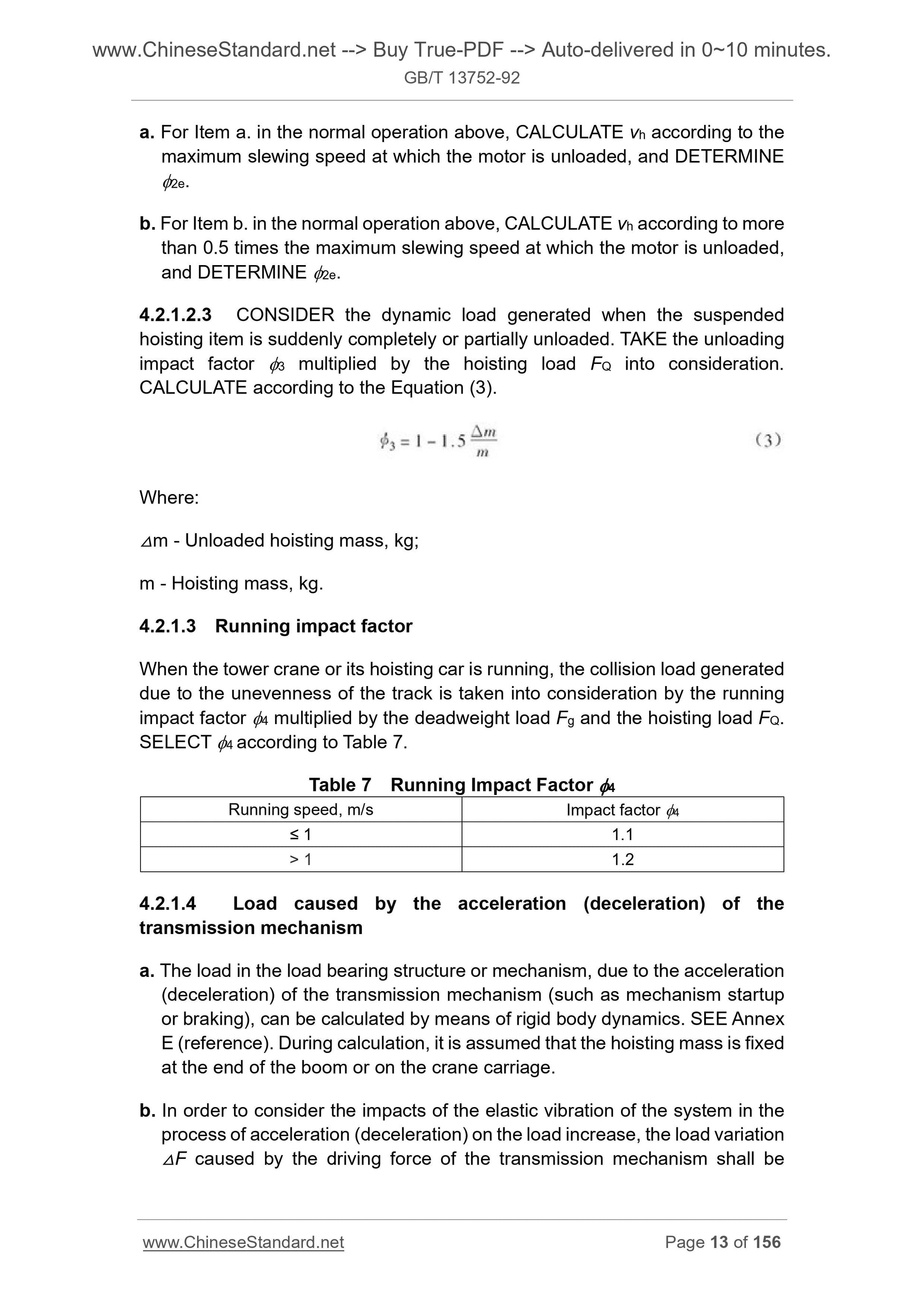
4.2.1.2.3 CONSIDER the dynamic load genera...
Get QUOTATION in 1-minute: Click GB/T 13752-1992
Historical versions: GB/T 13752-1992
Preview True-PDF (Reload/Scroll if blank)
GB/T 13752-1992: Design rules for tower cranes
GB/T 13752-92
GB
NATIONAL STANDARD OF THE
PEOPLE’S REPUBLIC OF CHINA
UDC 621.873.001.63
P 97
Design rules for tower cranes
ISSUED ON. NOVEMBER 5, 1992
IMPLEMENTED ON. MAY 1, 1993
Issued by. General Administration of Quality Supervision, Inspection and
Quarantine of the People’s Republic of China
3. No action is required - Full-copy of this standard will be automatically and
immediately delivered to your EMAIL address in 0~60 minutes.
Table of Contents
1 Subject content and scope of application ... 4
2 Normative references ... 4
3 Symbols and codes ... 5
4 General ... 8
5 Structure ... 27
6 Mechanism ... 54
7 Electric ... 79
Annex A (Supplement) Numerical table data for the stability calculation of the
structural members subjected to axial compression and the
bending structural members ... 90
Annex B (Supplement) Table for the fatigue strength calculation of the
structures ... 95
Annex C (Reference) Examples for the working levels of the tower cranes . 100
Annex D (Reference) Estimation method of the hoisting impact factor 1 ... 101
Annex E (Reference) Load generated by the acceleration (deceleration) of
the transmission mechanism ... 103
Annex F (Reference) Selection of the rail and wheel combination ... 107
Annex G (Reference) Determination of the axial force FN ... 108
Annex H (Reference) Calculated length factor μ ... 110
Annex I (Reference) Calculation equation for the bending moment coefficient
CH of the transverse load ... 121
Annex J (Reference) Stress amplitude method for the
fatigue strength calculation of the structure ... 124
Annex K (Reference) Standard load spectrum for the mechanism of the tower
crane ... 127
Annex L (Reference) Examples for the working levels of the tower crane’s
mechanism ... 128
Annex M (Reference) JC, Z values in the selection calculation of the
motor capacity for the tower crane’s mechanism ... 129
Annex N (Reference) Motor overload checking ... 130
Annex O (Reference) Heat checking of the asynchronous motors ... 132
Annex P (Reference) Stability checking of the oil cylinders ... 134
Annex Q (Reference) Method of determining the fatigue strength limit σrk .. 136
Annex R (Reference) Allowable physical quantity of the
commonly used friction surface material ... 142
Annex S (Reference) Selection coefficient C of the wire rope ... 143
Annex T (Reference) Calculation method of the reel wall thickness ... 144
Annex U (Reference) Calculation method of the slewing bearing selection . 147
Annex V (Reference) Current carrying capacity of the wire ... 153
Design rules for tower cranes
1 Subject content and scope of application
This Standard specifies the basic criteria and calculation methods that the
design calculation for tower cranes should follow. All other calculation methods
that are proved to be correct and reliable by theory and practice can also be
used.
This Standard is applicable to various types of power-driven tower cranes for
various uses.
This Standard is not applicable to the tower cranes converted by auto, tyre and
crawler cranes.
2 Normative references
GB 699 Quality carbon structural steels - Technical conditions
GB 700 Carbon structural steels
GB 755 Rotating electrical machines - General technical requirements
GB 985 Basic forms and sizes of weld grooves for gas welding, manual arc
welding and gas-shielded arc welding
GB 986 Basic forms and sizes of weld grooves for submerged arc welding
GB 998 Basic testing method of low voltage apparatus
GB 1591 Low alloy structural steels
GB 10051.1 Lifting hooks - Mechanical properties, lifting capacities, stresses
and materials
GB 1231 Specifications of high strength bolts with large hexagon head, large
hexagon nuts, plain washers for steel structure
GB 1300 Steel wires for welding
GB 3077 Alloy structure steel - Technical requirements
GB 3098.1 Mechanical properties of fasteners - Bolts, screws and studs
GB 3323 Methods for radiographic inspection and classification of
radiographs for fusion welded butt joints in steel
GB 3632 Sets of torshear type high strength bolt hexagon nut and plain
washer for steel structures
GB 3811 Design rules for cranes
GB 5117 Carbon steel covered electrodes
GB 5118 Low alloy steel electrodes
GB 5144 Safety rules for construction tower cranes
GB 10054 Builder’s hoist - Specification
GB 10055 Safety code for builder’s hoist
GB 11352 Carbon steel castings for general engineering purpose
JJ 3 Design rules for construction winches
JJ 12.1 Specification for welding quality of construction machinery
TJ 7 Code for design of industrial and civil building foundation
JJ 40 Fixed fill fluid coupling for tower cranes
JJ 75 Lifting equipment - Design requirements of the hook anti-off pawl
3 Symbols and codes
3.1 Loads
F - Concentrated load, force;
p - Pressure;
M - Bending moment, moment;
T - Torque.
3.2 Limit values for checking
σ - Calculated tensile and compressive stresses;
[σ] - Allowable stress of the materials;
σs - Yield point of the materials;
σb - Tensile strength of the materials;
σ0.2 - Test stress when the residual strain of the standard tensile test for
materials is up to 0.2%;
τ - Calculated shear stress;
[τ] - Allowable shear stress of the materials;
σrk - Fatigue strength limit;
E - Elastic modulus of the materials;
[λ] - Allowable slenderness ratio of the structural members;
λ - Slenderness ratio of the structural members;
σs - Maximum calculated tensile and compressive stress amplitudes;
τa - Maximum calculated shear stress amplitude;
[σa] - Allowable tensile and compressive fatigue stress amplitudes;
[τa] - Allowable shear fatigue stress amplitude.
3.3 Geometric parameters
l, L - Length, distance;
h - Height;
D, d - Diameter;
R, r - Radius;
b - Width;
e - Eccentricity;
Ia - Cross-sectional moment of inertia;
J - Moment of inertia;
W - Section bending modulus of the structural members;
A - Windward area of the structure, cross-sectional area of the structural
members;
P - Thread pitch, rope groove pitch;
δ - Thickness;
ᇞ - Displacement;
θ - Angle;
V - Volume.
3.4 Calculation coefficients
K, k - Dimensionless coefficient;
Kn - Safety factor;
Kf - Load spectral coefficient;
Ks - Structural stress spectral coefficient;
Km - Mechanism load spectral coefficient;
μ - Friction coefficient, length coefficient of the structural members;
α, β, f - Coefficients;
Cδ - Flexibility;
CW - Wind coefficient;
C - Wire rope selection coefficient;
C0 - Reduction factor of unequal end bending moment;
CH - Transverse load bending moment coefficient;
ω - Structural filling rate;
- Windshield reduction factor;
- Stability coefficient of the structural members subjected to axial compression;
ψ - Correction factor of axial compression stability;
W - Lateral buckling stability factor of the bending structural members;
1 - Hoisting impact factor;
2 - Hoisting dynamic load factor;
a. For Item a. in the normal operation above, CALCULATE vh according to the
maximum slewing speed at which the motor is unloaded, and DETERMINE
2e.
b. For Item b. in the normal operation above, CALCULATE vh according to more
than 0.5 times the maximum slewing speed at which the motor is unloaded,
and DETERMINE 2e.
4.2.1.2.3 CONSIDER the dynamic load genera...
Share