1
/
of
7
PayPal, credit cards. Download editable-PDF and invoice in 1 second!
GB/T 14118-1993 English PDF (GBT14118-1993)
GB/T 14118-1993 English PDF (GBT14118-1993)
Regular price
$240.00 USD
Regular price
Sale price
$240.00 USD
Unit price
/
per
Shipping calculated at checkout.
Couldn't load pickup availability
Delivery: 3 seconds. Download true-PDF + Invoice.
Get QUOTATION in 1-minute: Click GB/T 14118-1993
Historical versions: GB/T 14118-1993
Preview True-PDF (Reload/Scroll if blank)
GB/T 14118-1993: Harmonic drive reducers
GB/T 14118-1993
GB
NATIONAL STANDARD OF THE
PEOPLE’S REPUBLIC OF CHINA
GB/T 14118-93
Harmonic drive reducers
谐波齿轮减速器
ISSUED ON: MARCH 18, 1993
IMPLEMENTED ON: AUGUST 01, 1993
Issued by: State Bureau of Technical Supervision
Table of Contents
1 Scope ... 3
2 Normative references ... 3
3 Terms ... 3
4 Symbols and codes ... 5
5 Product classification ... 5
6 Technical requirements and test methods ... 14
7 Inspection rules ... 22
8 Marking, packaging, transportation and storage ... 23
Additional information ... 25
Harmonic drive reducers
1 Scope
This standard specifies the classification principles, technical requirements, test
methods and inspection rules of harmonic drive reducers.
This standard is mainly applicable to products in industries such as electronics,
aviation, aerospace, robotics, machine tools, textiles, medical treatment,
metallurgy, mining, etc.
2 Normative references
GB 699 Quality carbon structural steels - Technical conditions
GB 976 Classification and technical conditions of gray cast iron
GB 1096 Ordinary flat key - Type size
GB 1099 Half-round key - Type size
GB 2423.10 Electric and electronic products - Basic environmental test
regulations for electricians - Test Fc: The vibration (sine) method
GB 2828 Sampling procedures and tables for lot-by-lot inspection by
attributes (Apply to inspection of successive lots or batches)
GB 2829 Sampling procedures and tables for periodic inspection by
attributes (Apply to inspection of stability for productive process)
GB 6404 Determination of sound power level for noise emitted by gear units
YB 6 Alloy steel technical conditions
3 Terms
3.1 Harmonic drive
It is a transmission that uses a wave generator to generate a controllable
elastic deformation wave from a flexible gear, to realize movement and
power transmission.
In the working state, when the input shaft changes from forward to reverse
rotation, the lag of the output shaft on the angle of rotation.
3.13 Drive error
Under working conditions, when the input shaft rotates in one direction, the
difference between the actual rotation angle and theoretical rotation angle of
the output shaft.
4 Symbols and codes
4.1 XB - Cup type flexible gear harmonic drive reducer;
4.2 XBZ - Cup type flexible gear harmonic drive reducer with support;
4.3 A - Transmission accuracy level 1;
4.4 B - Transmission accuracy level 2;
4.5 C - Transmission accuracy level 3;
4.6 D - Transmission accuracy level 4;
4.7 A/B - Transmission accuracy mixed level, A means lost motion level 1 and
B means drive error level 2
4.8 Y - Lubricating oil;
4.9 ZH - Lubricating grease.
5 Product classification
5.1 Variety specifications
This standard harmonic drive reducer has 12 models and 60 transmission ratio
specifications. The same model includes several transmission ratios (see Table
3).
5.2 Type
This standard is a single-stage horizontal double-shaft extension type harmonic
drive reducer, which is divided into two types: large and small. Large reducer:
the flexible gear and output shaft are assembled (see Figure 1); small reducer:
the flexible gear and output shaft are integrated (see Figure 2).
5.3 Model
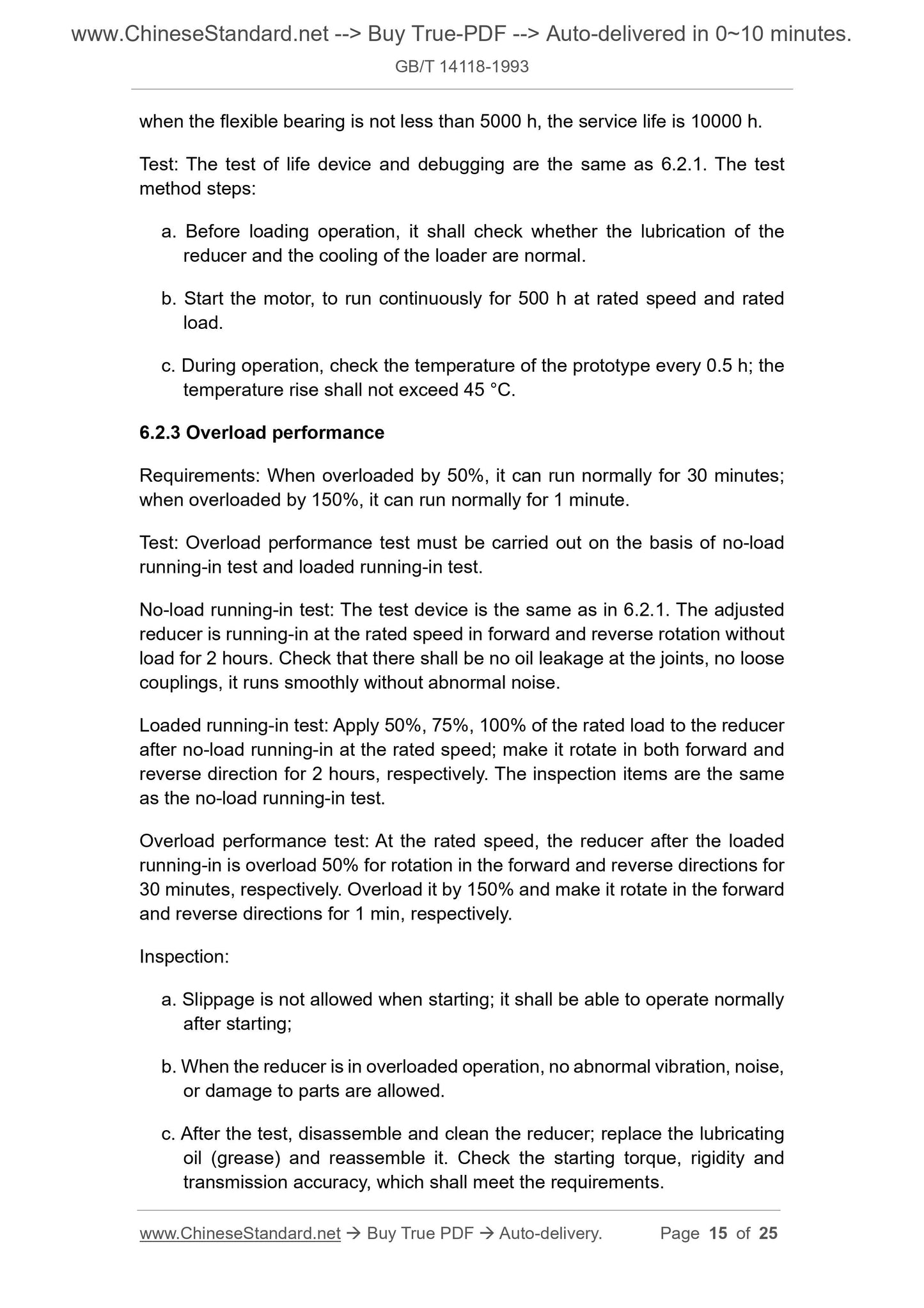
when the flexible bearing is not less than 5000 h, the service life is 10000 h.
Test: The test of life device and debugging are the same as 6.2.1. The test
method steps:
a. Before loading operation, it shall check whether the lubrication of the
reducer and the cooling of the loader are normal.
b. Start the motor, to run continuously for 500 h at rated speed and rated
load.
c. During operation, check the temperature of the prototype every 0.5 h; the
temperature rise shall not exceed 45 °C.
6.2.3 Overload performance
Requirements: When overloaded by 50%, it can run normally for 30 minutes;
when overloaded by 150%, it can run normally for 1 minute.
Test: Overload performance test must be carried out on the basis of no-load
running-in test and loaded running-in test.
No-load running-in test: The test device is the same as in 6.2.1. The adjusted
reducer is running-in at the rated speed in forward and reverse rotation without
load for 2 hours. Check that there shall be no oil leakage at the joints, no loose
couplings, it runs smoothly without abnormal noise.
Loaded running-in test: Apply 50%, 75%, 100% of the rated load to the reducer
after no-load running-in at the rated speed; make it rotate in both forward and
reverse direction for 2 hours, respectively. The inspection items are the same
as the no-load running-in test.
Overload performance test: At the rated speed, the reducer after the loaded
running-in is overload 50% for rotation in the forward and reverse directions for
30 minutes, respectively. Overload it by 150% and make it rotate in the forward
and reverse directions for 1 min, respectively.
Inspection:
a. Slippage is not allowed when starting; it shall be able to operate normally
after starting;
b. When the reducer is in overloaded operation, no abnormal vibration, noise,
or damage to parts are allowed.
c. After the test, disassemble and clean the reducer; replace the lubricating
oil (grease) and reassemble it. Check the starting torque, rigidity and
transmission accuracy, which shall meet the requirements.
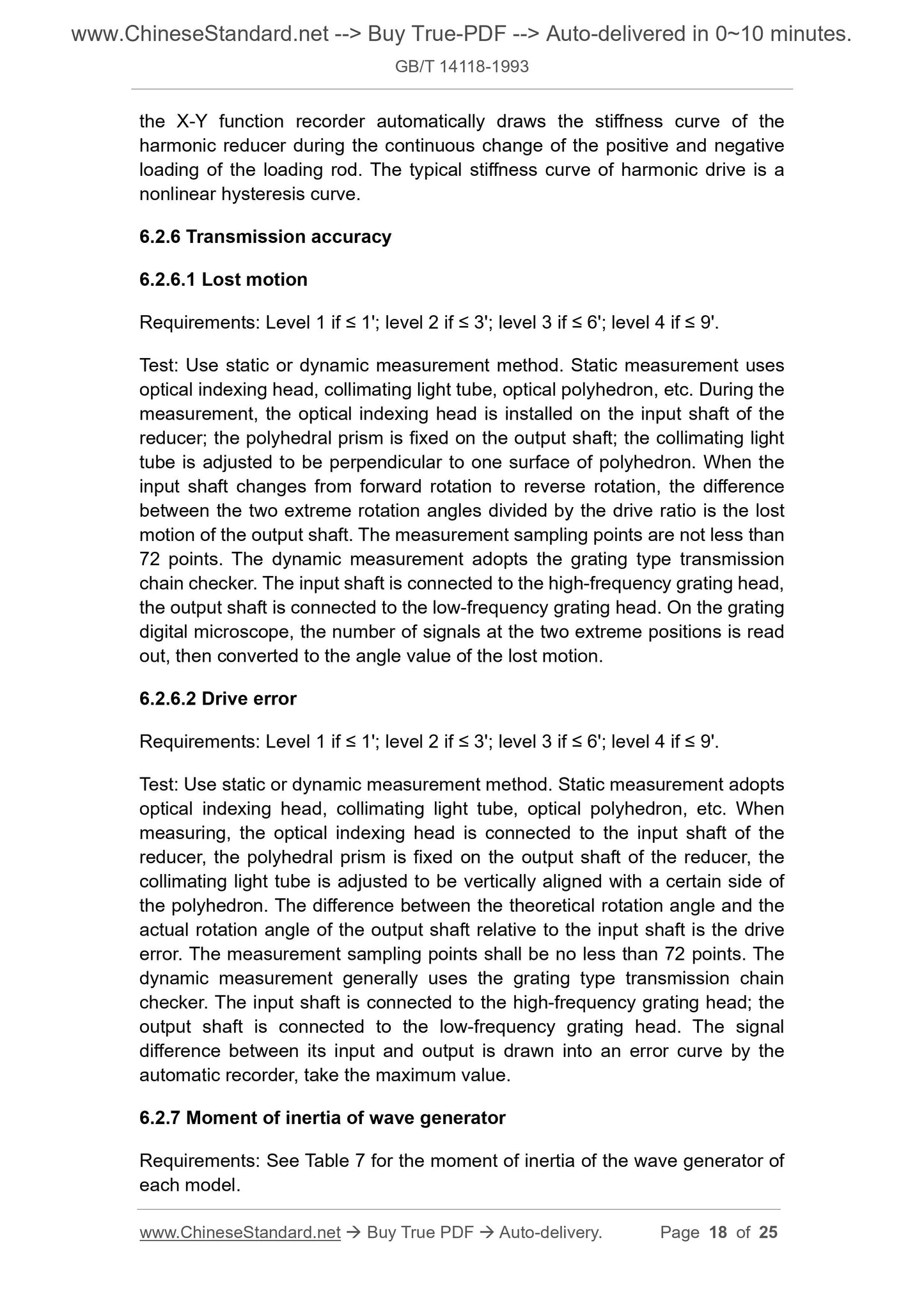
the X-Y function recorder automatically draws the stiffness curve of the
harmonic reducer during the continuous change of the positive and negative
loading of the loading rod. The typical stiffness curve of harmonic drive is a
nonlinear hysteresis curve.
6.2.6 Transmission accuracy
6.2.6.1 Lost motion
Requirements: Level 1 if ≤ 1'; level 2 if ≤ 3'; level 3 if ≤ 6'; level 4 if ≤ 9'.
Test: Use static or dynamic measurement method. Static measurement uses
optical indexing head, collimating light tube, optical polyhedron, etc. During the
measurement, the optical indexing head is installed on the input shaft of the
reducer; the polyhedral prism is fixed on the output shaft; the collimating light
tube is adjusted to be perpendicular to one surface of polyhedron. When the
input shaft changes from forward rotation to reverse rotation, the difference
between the two extreme rotation angles divided by the drive ratio is the lost
motion of the output shaft. The measurement sampling points are not less than
72 points. The dynamic measurement adopts the grating type transmission
chain checker. The input shaft is connected to the high-frequency grating head,
the output shaft is connected to the low-frequency grating head. On the grating
digital microscope, the number of signals at the two extreme positions is read
out, then converted to the angle value of the lost motion.
6.2.6.2 Drive error
Requirements: Level 1 if ≤ 1'; level 2 if ≤ 3'; level 3 if ≤ 6'; level 4 if ≤ 9'.
Test: Use static or dynamic measurement method. Static measurement adopts
optical indexing head, collimating light tube, optical polyhedron, etc. When
measuring, the optical indexing head is connected to the input shaft of the
reducer, the polyhedral prism is fixed on the output shaft of the reducer, the
collimating light tube is adjusted to be vertically aligned with a certain side of
the polyhedron. The difference between the theoretical rotation angle and the
actual rotation angle of the output shaft relative to the input shaft is the drive
error. The measurement sampling points shall be no less than 72 points. The
dynamic measu...
Get QUOTATION in 1-minute: Click GB/T 14118-1993
Historical versions: GB/T 14118-1993
Preview True-PDF (Reload/Scroll if blank)
GB/T 14118-1993: Harmonic drive reducers
GB/T 14118-1993
GB
NATIONAL STANDARD OF THE
PEOPLE’S REPUBLIC OF CHINA
GB/T 14118-93
Harmonic drive reducers
谐波齿轮减速器
ISSUED ON: MARCH 18, 1993
IMPLEMENTED ON: AUGUST 01, 1993
Issued by: State Bureau of Technical Supervision
Table of Contents
1 Scope ... 3
2 Normative references ... 3
3 Terms ... 3
4 Symbols and codes ... 5
5 Product classification ... 5
6 Technical requirements and test methods ... 14
7 Inspection rules ... 22
8 Marking, packaging, transportation and storage ... 23
Additional information ... 25
Harmonic drive reducers
1 Scope
This standard specifies the classification principles, technical requirements, test
methods and inspection rules of harmonic drive reducers.
This standard is mainly applicable to products in industries such as electronics,
aviation, aerospace, robotics, machine tools, textiles, medical treatment,
metallurgy, mining, etc.
2 Normative references
GB 699 Quality carbon structural steels - Technical conditions
GB 976 Classification and technical conditions of gray cast iron
GB 1096 Ordinary flat key - Type size
GB 1099 Half-round key - Type size
GB 2423.10 Electric and electronic products - Basic environmental test
regulations for electricians - Test Fc: The vibration (sine) method
GB 2828 Sampling procedures and tables for lot-by-lot inspection by
attributes (Apply to inspection of successive lots or batches)
GB 2829 Sampling procedures and tables for periodic inspection by
attributes (Apply to inspection of stability for productive process)
GB 6404 Determination of sound power level for noise emitted by gear units
YB 6 Alloy steel technical conditions
3 Terms
3.1 Harmonic drive
It is a transmission that uses a wave generator to generate a controllable
elastic deformation wave from a flexible gear, to realize movement and
power transmission.
In the working state, when the input shaft changes from forward to reverse
rotation, the lag of the output shaft on the angle of rotation.
3.13 Drive error
Under working conditions, when the input shaft rotates in one direction, the
difference between the actual rotation angle and theoretical rotation angle of
the output shaft.
4 Symbols and codes
4.1 XB - Cup type flexible gear harmonic drive reducer;
4.2 XBZ - Cup type flexible gear harmonic drive reducer with support;
4.3 A - Transmission accuracy level 1;
4.4 B - Transmission accuracy level 2;
4.5 C - Transmission accuracy level 3;
4.6 D - Transmission accuracy level 4;
4.7 A/B - Transmission accuracy mixed level, A means lost motion level 1 and
B means drive error level 2
4.8 Y - Lubricating oil;
4.9 ZH - Lubricating grease.
5 Product classification
5.1 Variety specifications
This standard harmonic drive reducer has 12 models and 60 transmission ratio
specifications. The same model includes several transmission ratios (see Table
3).
5.2 Type
This standard is a single-stage horizontal double-shaft extension type harmonic
drive reducer, which is divided into two types: large and small. Large reducer:
the flexible gear and output shaft are assembled (see Figure 1); small reducer:
the flexible gear and output shaft are integrated (see Figure 2).
5.3 Model
when the flexible bearing is not less than 5000 h, the service life is 10000 h.
Test: The test of life device and debugging are the same as 6.2.1. The test
method steps:
a. Before loading operation, it shall check whether the lubrication of the
reducer and the cooling of the loader are normal.
b. Start the motor, to run continuously for 500 h at rated speed and rated
load.
c. During operation, check the temperature of the prototype every 0.5 h; the
temperature rise shall not exceed 45 °C.
6.2.3 Overload performance
Requirements: When overloaded by 50%, it can run normally for 30 minutes;
when overloaded by 150%, it can run normally for 1 minute.
Test: Overload performance test must be carried out on the basis of no-load
running-in test and loaded running-in test.
No-load running-in test: The test device is the same as in 6.2.1. The adjusted
reducer is running-in at the rated speed in forward and reverse rotation without
load for 2 hours. Check that there shall be no oil leakage at the joints, no loose
couplings, it runs smoothly without abnormal noise.
Loaded running-in test: Apply 50%, 75%, 100% of the rated load to the reducer
after no-load running-in at the rated speed; make it rotate in both forward and
reverse direction for 2 hours, respectively. The inspection items are the same
as the no-load running-in test.
Overload performance test: At the rated speed, the reducer after the loaded
running-in is overload 50% for rotation in the forward and reverse directions for
30 minutes, respectively. Overload it by 150% and make it rotate in the forward
and reverse directions for 1 min, respectively.
Inspection:
a. Slippage is not allowed when starting; it shall be able to operate normally
after starting;
b. When the reducer is in overloaded operation, no abnormal vibration, noise,
or damage to parts are allowed.
c. After the test, disassemble and clean the reducer; replace the lubricating
oil (grease) and reassemble it. Check the starting torque, rigidity and
transmission accuracy, which shall meet the requirements.
the X-Y function recorder automatically draws the stiffness curve of the
harmonic reducer during the continuous change of the positive and negative
loading of the loading rod. The typical stiffness curve of harmonic drive is a
nonlinear hysteresis curve.
6.2.6 Transmission accuracy
6.2.6.1 Lost motion
Requirements: Level 1 if ≤ 1'; level 2 if ≤ 3'; level 3 if ≤ 6'; level 4 if ≤ 9'.
Test: Use static or dynamic measurement method. Static measurement uses
optical indexing head, collimating light tube, optical polyhedron, etc. During the
measurement, the optical indexing head is installed on the input shaft of the
reducer; the polyhedral prism is fixed on the output shaft; the collimating light
tube is adjusted to be perpendicular to one surface of polyhedron. When the
input shaft changes from forward rotation to reverse rotation, the difference
between the two extreme rotation angles divided by the drive ratio is the lost
motion of the output shaft. The measurement sampling points are not less than
72 points. The dynamic measurement adopts the grating type transmission
chain checker. The input shaft is connected to the high-frequency grating head,
the output shaft is connected to the low-frequency grating head. On the grating
digital microscope, the number of signals at the two extreme positions is read
out, then converted to the angle value of the lost motion.
6.2.6.2 Drive error
Requirements: Level 1 if ≤ 1'; level 2 if ≤ 3'; level 3 if ≤ 6'; level 4 if ≤ 9'.
Test: Use static or dynamic measurement method. Static measurement adopts
optical indexing head, collimating light tube, optical polyhedron, etc. When
measuring, the optical indexing head is connected to the input shaft of the
reducer, the polyhedral prism is fixed on the output shaft of the reducer, the
collimating light tube is adjusted to be vertically aligned with a certain side of
the polyhedron. The difference between the theoretical rotation angle and the
actual rotation angle of the output shaft relative to the input shaft is the drive
error. The measurement sampling points shall be no less than 72 points. The
dynamic measu...
Share