1
/
of
4
www.ChineseStandard.us -- Field Test Asia Pte. Ltd.
GB/T 14517-1993 English PDF (GB/T14517-1993)
GB/T 14517-1993 English PDF (GB/T14517-1993)
Regular price
$205.00
Regular price
Sale price
$205.00
Unit price
/
per
Shipping calculated at checkout.
Couldn't load pickup availability
GB/T 14517-1993: Test method for dielectric strength of insulating adhesive tape at power frequency
Delivery: 9 seconds. Download (& Email) true-PDF + Invoice.
Get Quotation: Click GB/T 14517-1993 (Self-service in 1-minute)
Historical versions (Master-website): GB/T 14517-1993
Preview True-PDF (Reload/Scroll-down if blank)
GB/T 14517-1993
GB
NATIONAL STANDARD OF THE
PEOPLE’S REPUBLIC OF CHINA
UDC 621.315.611
G 38
GB/T 14517-93
Test method for dielectric strength of
insulating adhesive tape at power frequency
ISSUED ON. JUNE 15, 1993
IMPLEMENTED ON. APRIL 1, 1994
Issued by. State Bureau of Technical Supervision
Table of Contents
1 Subject content and application scope ... 3
2 Definitions ... 3
3 Test equipment ... 3
4 Test conditions ... 5
5 Sample ... 5
6 Test steps ... 6
7 Test report ... 6
Additional information... 7
Test method for dielectric strength of
insulating adhesive tape at power frequency
This Standard referred to International Electrotechnical Commission (IEC)
publication 243-1-1988 “Methods of test for electric strength of solid insulating
materials, Part 1. Tests at power frequencies”.
1 Subject content and application scope
This Standard specifies the sample preparation, test equipment and test steps
for test of dielectric strength of insulating adhesive tape at power frequency.
This Standard is applicable to the determination of dielectric strength of
insulating adhesive tape at power frequency.
2 Definitions
Dielectric strength -- The sample is not broken down within a specified time
under the action of a certain power frequency voltage, expressed in kilovolts
and minutes.
Breakdown -- The sample has traces of through holes, cracks, burns, etc. along
the direction of the applied voltage.
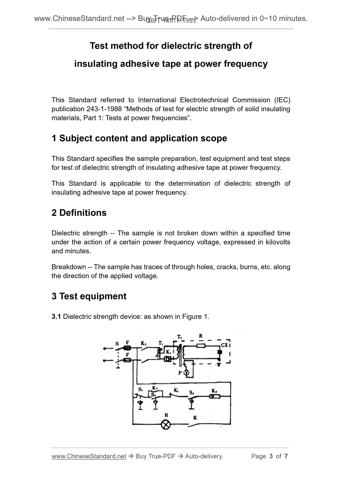
3 Test equipment
3.1 Dielectric strength device. as shown in Figure 1.
The sample shall be clean, dry, free of impurities and bubbles, and the adhesive
layer has no significant uneven areas.
6 Test steps
6.1 Check the grounding wire of the dielectric strength device to ensure good
grounding.
6.2 Loosen the wing nut on the top of the electrode assembly, take out the upper
cover of the electrode device, and install the sample as shown in Figure 2. In
order to prevent arcing at the edge of the sample, an insulating adhesive tape
can be used to overlap the sample at the edge of the sample. Install the upper
cover and tighten the wing nut.
6.3 Connect one end of the high voltage cable to the AC high voltage output of
the dielectric strength device AND the other end to an upper electrode of the
electrode device.
6.4 Connect one end of the test cable to the test end of the dielectric strength
device and the other end to the lower electrode of the electrode assembly.
6.5 Select the voltage range on the dielectric strength device according to the
specified test voltage.
6.6 Select the time range on the dielectric strength device according to the
specified dielectric strength time.
6.7 Turn on the power, turn on the power switch of the dielectric strength device,
and warm up the device for a few minutes.
6.8 The tester stands on the insulating rubber plate, press the voltage-rise
switch to continuously and evenly rise to the test voltage within 10~20 s. At the
same time, press the stopwatch to start timing.
6.9 When the dielectric strength time is over, press the return switch to lower
the voltage to zero and remove the sample.
6.10 If the sample is broken during the voltage-rise process or during the
dielectric strength, the test voltage is automatically reduced to zero. Remove
the sample and observe the part where the sample is in contact with the
electrode. Record the form in which the sample is broken down, such as small
holes, cracking, charring, etc.
7 Test report
The test report shall contain the following information.
GB/T 14517-1993
GB
NATIONAL STANDARD OF THE
PEOPLE’S REPUBLIC OF CHINA
UDC 621.315.611
G 38
GB/T 14517-93
Test method for dielectric strength of
insulating adhesive tape at power frequency
ISSUED ON. JUNE 15, 1993
IMPLEMENTED ON. APRIL 1, 1994
Issued by. State Bureau of Technical Supervision
Table of Contents
1 Subject content and application scope ... 3
2 Definitions ... 3
3 Test equipment ... 3
4 Test conditions ... 5
5 Sample ... 5
6 Test steps ... 6
7 Test report ... 6
Additional information... 7
Test method for dielectric strength of
insulating adhesive tape at power frequency
This Standard referred to International Electrotechnical Commission (IEC)
publication 243-1-1988 “Methods of test for electric strength of solid insulating
materials, Part 1. Tests at power frequencies”.
1 Subject content and application scope
This Standard specifies the sample preparation, test equipment and test steps
for test of dielectric strength of insulating adhesive tape at power frequency.
This Standard is applicable to the determination of dielectric strength of
insulating adhesive tape at power frequency.
2 Definitions
Dielectric strength -- The sample is not broken down within a specified time
under the action of a certain power frequency voltage, expressed in kilovolts
and minutes.
Breakdown -- The sample has traces of through holes, cracks, burns, etc. along
the direction of the applied voltage.
3 Test equipment
3.1 Dielectric strength device. as shown in Figure 1.
The sample shall be clean, dry, free of impurities and bubbles, and the adhesive
layer has no significant uneven areas.
6 Test steps
6.1 Check the grounding wire of the dielectric strength device to ensure good
grounding.
6.2 Loosen the wing nut on the top of the electrode assembly, take out the upper
cover of the electrode device, and install the sample as shown in Figure 2. In
order to prevent arcing at the edge of the sample, an insulating adhesive tape
can be used to overlap the sample at the edge of the sample. Install the upper
cover and tighten the wing nut.
6.3 Connect one end of the high voltage cable to the AC high voltage output of
the dielectric strength device AND the other end to an upper electrode of the
electrode device.
6.4 Connect one end of the test cable to the test end of the dielectric strength
device and the other end to the lower electrode of the electrode assembly.
6.5 Select the voltage range on the dielectric strength device according to the
specified test voltage.
6.6 Select the time range on the dielectric strength device according to the
specified dielectric strength time.
6.7 Turn on the power, turn on the power switch of the dielectric strength device,
and warm up the device for a few minutes.
6.8 The tester stands on the insulating rubber plate, press the voltage-rise
switch to continuously and evenly rise to the test voltage within 10~20 s. At the
same time, press the stopwatch to start timing.
6.9 When the dielectric strength time is over, press the return switch to lower
the voltage to zero and remove the sample.
6.10 If the sample is broken during the voltage-rise process or during the
dielectric strength, the test voltage is automatically reduced to zero. Remove
the sample and observe the part where the sample is in contact with the
electrode. Record the form in which the sample is broken down, such as small
holes, cracking, charring, etc.
7 Test report
The test report shall contain the following information.
Delivery: 9 seconds. Download (& Email) true-PDF + Invoice.
Get Quotation: Click GB/T 14517-1993 (Self-service in 1-minute)
Historical versions (Master-website): GB/T 14517-1993
Preview True-PDF (Reload/Scroll-down if blank)
GB/T 14517-1993
GB
NATIONAL STANDARD OF THE
PEOPLE’S REPUBLIC OF CHINA
UDC 621.315.611
G 38
GB/T 14517-93
Test method for dielectric strength of
insulating adhesive tape at power frequency
ISSUED ON. JUNE 15, 1993
IMPLEMENTED ON. APRIL 1, 1994
Issued by. State Bureau of Technical Supervision
Table of Contents
1 Subject content and application scope ... 3
2 Definitions ... 3
3 Test equipment ... 3
4 Test conditions ... 5
5 Sample ... 5
6 Test steps ... 6
7 Test report ... 6
Additional information... 7
Test method for dielectric strength of
insulating adhesive tape at power frequency
This Standard referred to International Electrotechnical Commission (IEC)
publication 243-1-1988 “Methods of test for electric strength of solid insulating
materials, Part 1. Tests at power frequencies”.
1 Subject content and application scope
This Standard specifies the sample preparation, test equipment and test steps
for test of dielectric strength of insulating adhesive tape at power frequency.
This Standard is applicable to the determination of dielectric strength of
insulating adhesive tape at power frequency.
2 Definitions
Dielectric strength -- The sample is not broken down within a specified time
under the action of a certain power frequency voltage, expressed in kilovolts
and minutes.
Breakdown -- The sample has traces of through holes, cracks, burns, etc. along
the direction of the applied voltage.
3 Test equipment
3.1 Dielectric strength device. as shown in Figure 1.
The sample shall be clean, dry, free of impurities and bubbles, and the adhesive
layer has no significant uneven areas.
6 Test steps
6.1 Check the grounding wire of the dielectric strength device to ensure good
grounding.
6.2 Loosen the wing nut on the top of the electrode assembly, take out the upper
cover of the electrode device, and install the sample as shown in Figure 2. In
order to prevent arcing at the edge of the sample, an insulating adhesive tape
can be used to overlap the sample at the edge of the sample. Install the upper
cover and tighten the wing nut.
6.3 Connect one end of the high voltage cable to the AC high voltage output of
the dielectric strength device AND the other end to an upper electrode of the
electrode device.
6.4 Connect one end of the test cable to the test end of the dielectric strength
device and the other end to the lower electrode of the electrode assembly.
6.5 Select the voltage range on the dielectric strength device according to the
specified test voltage.
6.6 Select the time range on the dielectric strength device according to the
specified dielectric strength time.
6.7 Turn on the power, turn on the power switch of the dielectric strength device,
and warm up the device for a few minutes.
6.8 The tester stands on the insulating rubber plate, press the voltage-rise
switch to continuously and evenly rise to the test voltage within 10~20 s. At the
same time, press the stopwatch to start timing.
6.9 When the dielectric strength time is over, press the return switch to lower
the voltage to zero and remove the sample.
6.10 If the sample is broken during the voltage-rise process or during the
dielectric strength, the test voltage is automatically reduced to zero. Remove
the sample and observe the part where the sample is in contact with the
electrode. Record the form in which the sample is broken down, such as small
holes, cracking, charring, etc.
7 Test report
The test report shall contain the following information.
Share