1
/
of
12
www.ChineseStandard.us -- Field Test Asia Pte. Ltd.
GB/T 150.3-2024 English PDF (GB/T150.3-2024)
GB/T 150.3-2024 English PDF (GB/T150.3-2024)
Regular price
$3,505.00
Regular price
Sale price
$3,505.00
Unit price
/
per
Shipping calculated at checkout.
Couldn't load pickup availability
GB/T 150.3-2024: Pressure vessels - Part 3: Design
Delivery: 9 seconds. Download (& Email) true-PDF + Invoice.
Get Quotation: Click GB/T 150.3-2024 (Self-service in 1-minute)
Historical versions (Master-website): GB/T 150.3-2024
Preview True-PDF (Reload/Scroll-down if blank)
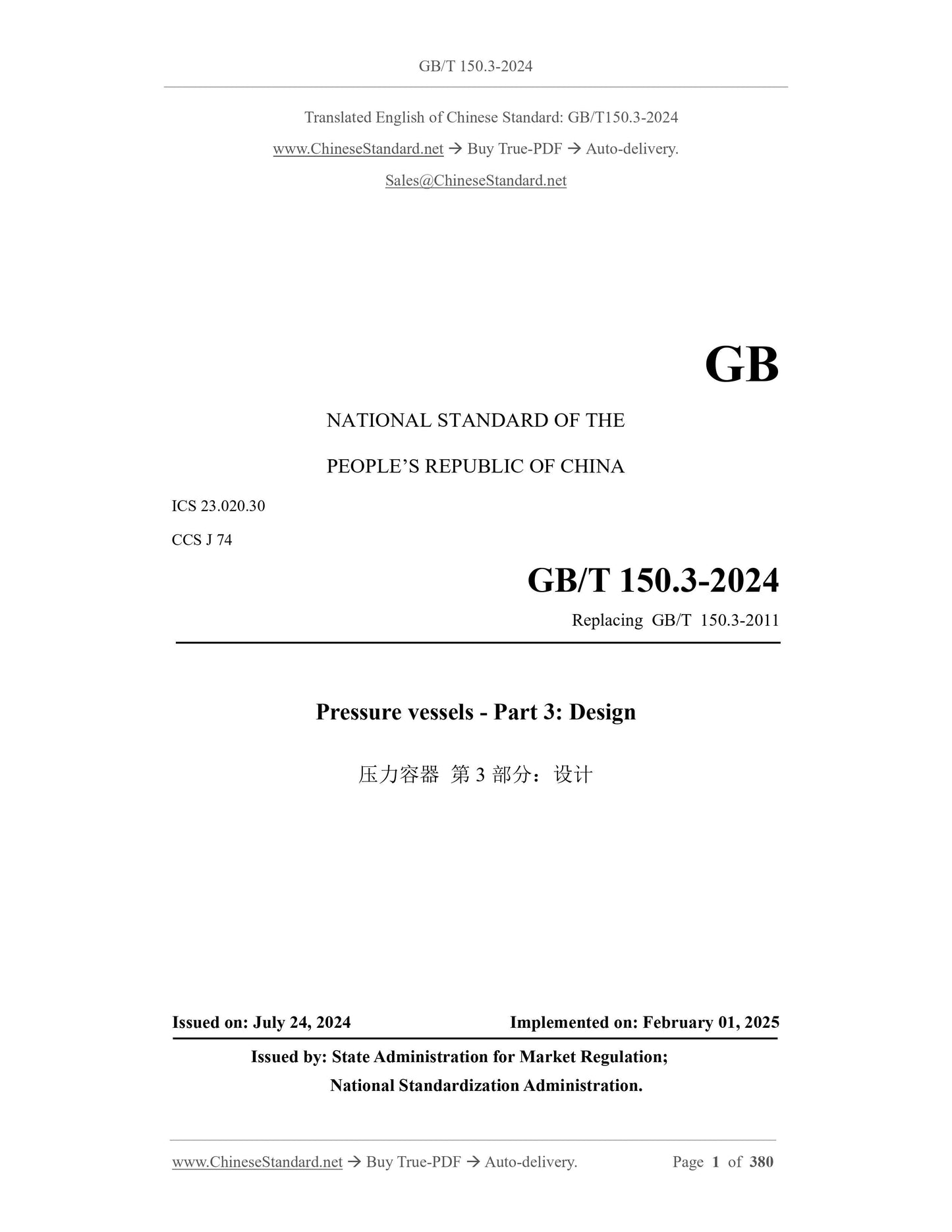
GB/T 150.3-2024
GB
NATIONAL STANDARD OF THE
PEOPLE’S REPUBLIC OF CHINA
ICS 23.020.30
CCS J 74
Replacing GB/T 150.3-2011
Pressure vessels - Part 3: Design
ISSUED ON: JULY 24, 2024
IMPLEMENTED ON: FEBRUARY 01, 2025
Issued by: State Administration for Market Regulation;
National Standardization Administration.
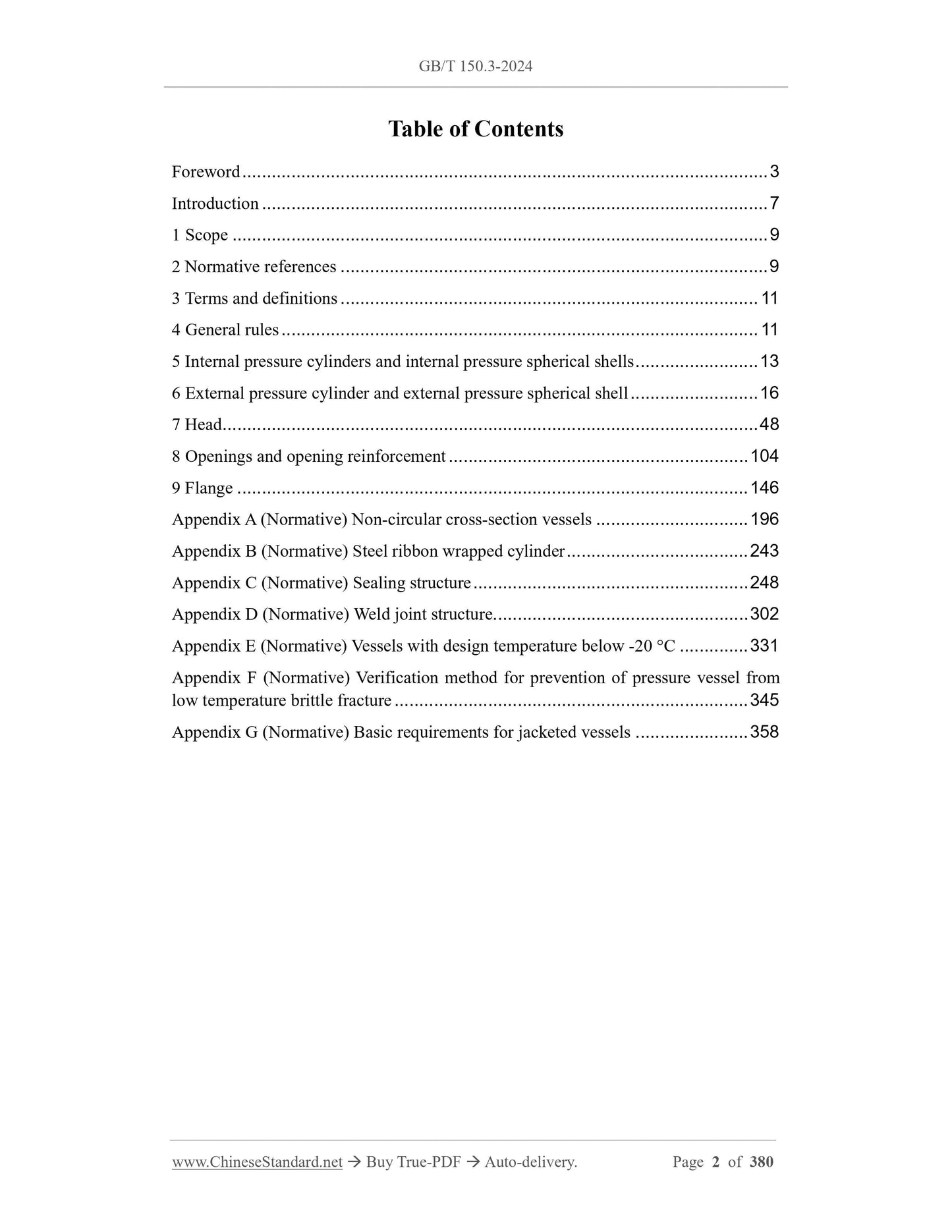
Table of Contents
Foreword ... 3
Introduction ... 7
1 Scope ... 9
2 Normative references ... 9
3 Terms and definitions ... 11
4 General rules ... 11
5 Internal pressure cylinders and internal pressure spherical shells ... 13
6 External pressure cylinder and external pressure spherical shell ... 16
7 Head ... 48
8 Openings and opening reinforcement ... 104
9 Flange ... 146
Appendix A (Normative) Non-circular cross-section vessels ... 196
Appendix B (Normative) Steel ribbon wrapped cylinder ... 243
Appendix C (Normative) Sealing structure ... 248
Appendix D (Normative) Weld joint structure ... 302
Appendix E (Normative) Vessels with design temperature below -20 °C ... 331
Appendix F (Normative) Verification method for prevention of pressure vessel from
low temperature brittle fracture ... 345
Appendix G (Normative) Basic requirements for jacketed vessels ... 358
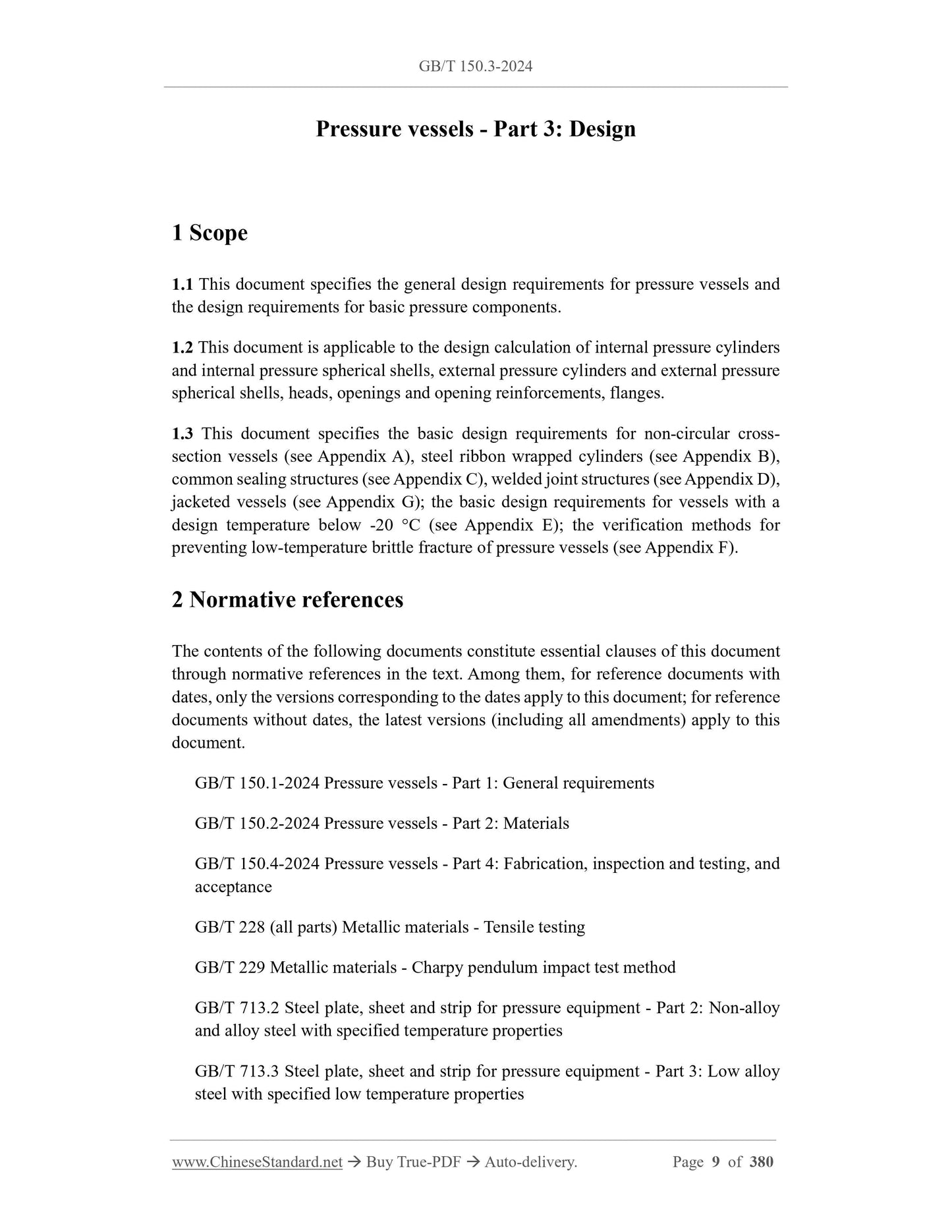
Pressure vessels - Part 3: Design
1 Scope
1.1 This document specifies the general design requirements for pressure vessels and
the design requirements for basic pressure components.
1.2 This document is applicable to the design calculation of internal pressure cylinders
and internal pressure spherical shells, external pressure cylinders and external pressure
spherical shells, heads, openings and opening reinforcements, flanges.
1.3 This document specifies the basic design requirements for non-circular cross-
section vessels (see Appendix A), steel ribbon wrapped cylinders (see Appendix B),
common sealing structures (see Appendix C), welded joint structures (see Appendix D),
jacketed vessels (see Appendix G); the basic design requirements for vessels with a
design temperature below -20 °C (see Appendix E); the verification methods for
preventing low-temperature brittle fracture of pressure vessels (see Appendix F).
2 Normative references
The contents of the following documents constitute essential clauses of this document
through normative references in the text. Among them, for reference documents with
dates, only the versions corresponding to the dates apply to this document; for reference
documents without dates, the latest versions (including all amendments) apply to this
document.
GB/T 150.1-2024 Pressure vessels - Part 1: General requirements
GB/T 150.2-2024 Pressure vessels - Part 2: Materials
GB/T 150.4-2024 Pressure vessels - Part 4: Fabrication, inspection and testing, and
acceptance
GB/T 228 (all parts) Metallic materials - Tensile testing
GB/T 229 Metallic materials - Charpy pendulum impact test method
GB/T 713.2 Steel plate, sheet and strip for pressure equipment - Part 2: Non-alloy
and alloy steel with specified temperature properties
GB/T 713.3 Steel plate, sheet and strip for pressure equipment - Part 3: Low alloy
steel with specified low temperature properties
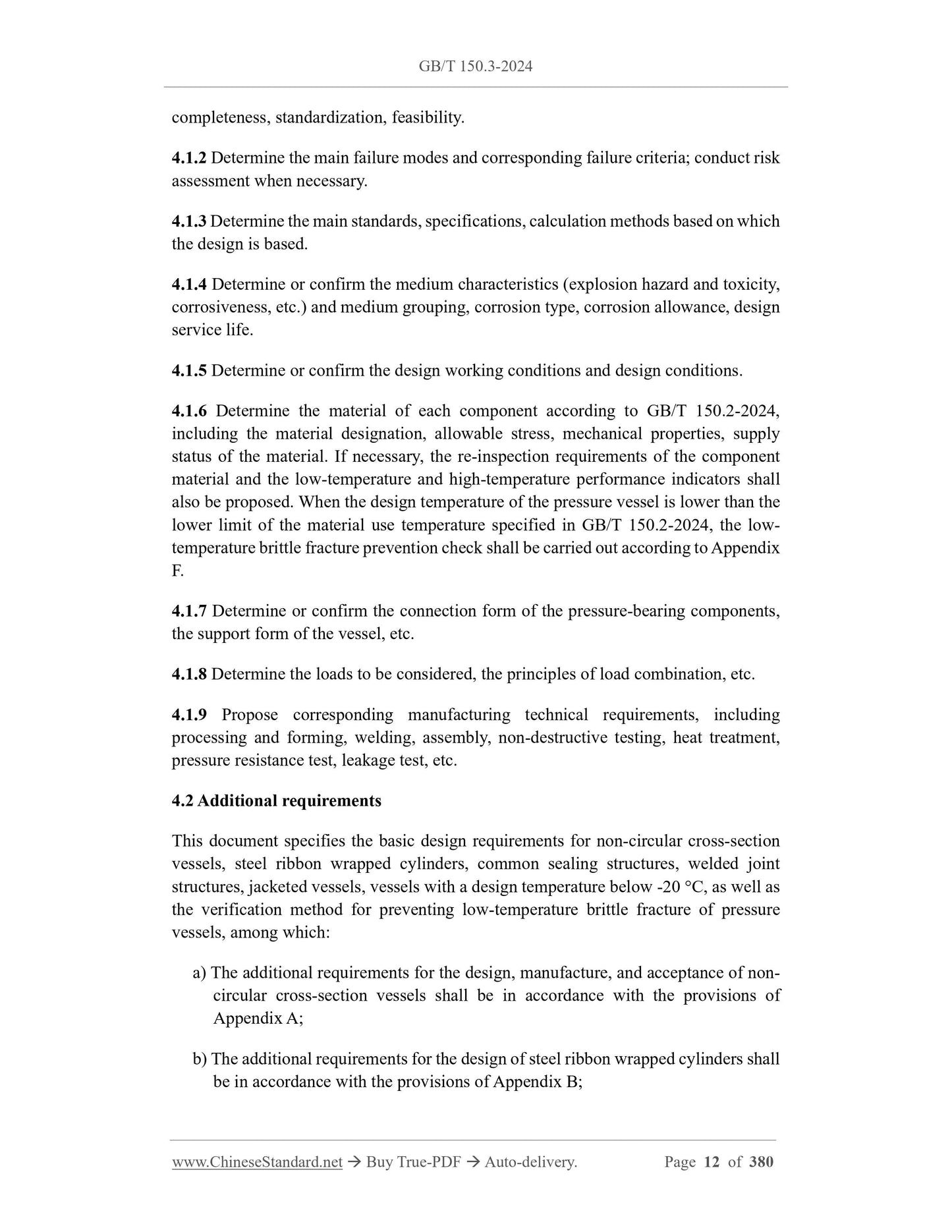
completeness, standardization, feasibility.
4.1.2 Determine the main failure modes and corresponding failure criteria; conduct risk
assessment when necessary.
4.1.3 Determine the main standards, specifications, calculation methods based on which
the design is based.
4.1.4 Determine or confirm the medium characteristics (explosion hazard and toxicity,
corrosiveness, etc.) and medium grouping, corrosion type, corrosion allowance, design
service life.
4.1.5 Determine or confirm the design working conditions and design conditions.
4.1.6 Determine the material of each component according to GB/T 150.2-2024,
including the material designation, allowable stress, mechanical properties, supply
status of the material. If necessary, the re-inspection requirements of the component
material and the low-temperature and high-temperature performance indicators shall
also be proposed. When the design temperature of the pressure vessel is lower than the
lower limit of the material use temperature specified in GB/T 150.2-2024, the low-
temperature brittle fracture prevention check shall be carried out according to Appendix
F.
4.1.7 Determine or confirm the connection form of the pressure-bearing components,
the support form of the vessel, etc.
4.1.8 Determine the loads to be considered, the principles of load combination, etc.
4.1.9 Propose corresponding manufacturing technical requirements, including
processing and forming, welding, assembly, non-destructive testing, heat treatment,
pressure resistance test, leakage test, etc.
4.2 Additional requirements
This document specifies the basic design requirements for non-circular cross-section
vessels, steel ribbon wrapped cylinders, common sealing structures, welded joint
structures, jacketed vessels, vessels with a design temperature below -20 °C, as well as
the verification method for preventing low-temperature brittle fracture of pressure
vessels, among which:
a) The additional requirements for the design, manufacture, and acceptance of non-
circular cross-section vessels shall be in accordance with the provisions of
Appendix A;
b) The additional requirements for the design of steel ribbon wrapped cylinders shall
be in accordance with the provisions of Appendix B;
edge or conical shell with folding edge and transition section shall not be less than
the required thickness of the connected cylinder. In addition, when the conical
shell and the cylinder are connected without folding edge, it shall also meet the
area verification requirements (see 7.6.6.4.1 or 7.6.6.5.1).
b) As shown in b-1) in Figure 6-1, the calculated length shall be the total length of
the equipment. At this time, the length L shown, the outer diameter of each
cylinder at the connection, the corresponding thickness shall be used for design
calculation. The required thickness of the conical shell without folding edge or
conical shell with folding edge and transition section shall not be less than the
required thickness of the connected cylinder. In addition, when the connection
between the conical shell and the cylinder is not provided with a folded edge, it
shall also meet the area verification requirements (see 7.6.6.4.1 or 7.6.6.5.1).
As shown in b-2) in Figure 6-1, when the connection between the cylinder and the
conical shell can be considered as a support line, the calculated length of the cylinder
part is the total length of the cylinder. The connection between the cylinder and the
conical shell shall meet the requirements of 7.6.6.4 or 7.6.6.5. When the moment of
inertia of the cylinder-conical shell combined section as a support line is insufficient,
a cylinder-conical shell-reinforcement ring combined structure is allowed to
increase the moment of inertia of the combined section to meet the requirements of
7.6.6.4.2 or 7.6.6.5.2.
c) As shown in c-1) and c-2) in Figure 6-1, when the cylinder part has a
reinforcement ring (or can be used as a reinforcement member), the calculated
length is the distance between the center lines of adjacent reinforcement rings.
According to c-2) in Figure 6-1, the length L shown, the outer diameter of each
cylinder at the connection, the corresponding thickness shall be used for design
calculation. The required thickness of the conical shell without folded edge or the
conical shell with folded edge and the transition section shall not be less than the
required thickness of the connected cylinder. In addition, when the conical shell and
the cylinder are connected without folded edges, it shall meet the area verification
requirements (see 7.6.6.4.1 or 7.6.6.5.1).
d) As shown in d) in Figure 6-1, the calculated length is the distance between the
center line of the first reinforcement ring of the cylinder and the tangent line of
the convex head plus 1/3 of the depth of the convex head’s curved surface.
e) As shown in e-1), e-2), f) in Figure 6-1, when the connection between the cylinder
and the conical shell can be used as a support line, the calculated length is the
distance between this connection and the adjacent support line. The connection
between the cylinder and the conical shell shall meet the requirements of 7.6.6.4
or 7.6.6.5; when the moment of inertia of the cylinder-conical shell combined
section as the support line is insufficient, the cylinder-conical shell-reinforcement
ring combined structure is allowed to increase the moment of inertia of the
following rules.
a) When the large end or the large and small ends of the conical shell have a
reinforcement section or a transition section at the same time, the calculated
thickness of each part of the conical head shall be determined according to 7.6.3
~ 7.6.5. If it is considered to be composed of only one thickness, the maximum
value of the thickness of the above parts shall be taken as the thickness of the
conical head.
b) In any case, the effective thickness of the transition section or reinforcement
section shall not be less than the calculated thickness of the conical shell
connected to it, meanwhile it shall not be less than 0.15% of the inner diameter
of the cylinder.
c) For conical heads subjected to external pressure, the strength requirements under
the internal pressure design conditions shall be met first.
7.6.1.4 The connection between the conical shell and the cylinder shall adopt a full
penetration structure.
7.6.2 Symbols
The following symbols apply to this section:
A - Strain coefficient for external pressure calculation;
AeL - Effective reinforcement cross-sectional area at the connection between the
large end of the conical shell and the cylinder, when calculating external pressure,
mm2;
Aes - Effective reinforcement cross-sectional area at the connection between the
small end of the conical shell and the cylinder, when calculating external pressure,
mm2;
ArL - Cross-sectional area of the large end of the conical shell that needs to be
reinforced, mm2;
Ars - Cross-sectional area of the small end of the conical shell that needs to be
reinforced, mm2;
As - Cross-sectional area of the reinforcement ring, mm2;
AT - Equivalent cross-sectional area of the cylinder, conical shell, reinforcement ring,
where the large end is ATL, as shown in formula (7-34), the small end is ATs, as
shown in formula (7-39), mm2;
B - Stress coefficient for external pressure calculation, MPa;
C - Thickness addition (according to GB/T 150.1-2024), mm;
Dc - Calculated inner diameter of the conical shell, mm;
Di - Inner diameter of the cylinder, mm;
DiL - Inner diameter of the straight edge section at the large end of the conical shell,
mm;
Dis - Inner diameter of the straight edge section at the small end of the conical shell,
mm;
DL - The outer diameter of the large end of the conical shell section considered in
the external pressure calculation (see Figure 7-18), mm;
DoL - The outer diameter of the straight edge section at the large end of the conical
shell, mm;
Dos - The outer diameter of the straight edge section at the small end of the conical
shell, mm;
Ds - The outer diameter of the small end of the conical shell section considered in
the external pressure calculation (see Figure 7-18), mm;
Ec, Er, Es - The elastic modulus of the material at the design temperature, wherein
Ec, Er, Es represent the conical shell, reinforcement ring, cylinder, respectively, MPa;
f1 - In addition to the pressure load, the axial force per unit circumference length
generated by the external load at the large end of the conical shell, N/mm;
f2 - In addition to the pressure load, the axial force per unit circumference length
generated by the external load at the small end of the conical shell, N/mm;
I - The required moment of inertia of the cylinder-conical shell or reinforcement
ring-cylinder-conical shell combination, mm4;
Is - The moment of inertia of the effective cross section of the cylinder-conical shell
or reinforcement ring-cylinder-conical shell combination about the centroidal axis
parallel to the shell axis, mm4;
k - Coefficient, see formula (7-17);
Lc - The length between the two reinforcement rings on the conical shell measured
along the conical shell surface, mm;
Le - The equivalent length of the conical shell, mm;
LL - The calculated length of the cylinder connected to the large end of the conical
Multiple opening reinforcement of shell meets the following requirements.
a) When the center distance between any two adjacent openings is less than the
sum of the diameters of the two openings, whilst their reinforcement ranges
overlap each other (see Figure 8-3), joint reinforcement is adopted in the shell
method section passing through the line connecting the center points of the two
openings. The total area of joint reinforcement shall not be less than the sum of
the areas required for the individual reinforcement of each opening (calculated
according to 8.3.3 and 8.3.5), meanwhile the reinforcement area between the two
openings shall not be less than 50% of the total reinforcement area required for
the two openings.
When calculating the joint reinforcement area, no section shall be counted
repeatedly.
When the center lines of multiple openings are on the same straight line, they
shall be treated as paired openings; the area of the overlapping part shall be
apportioned according to the diameter ratio of the two adjacent openings.
b) For 3 or more openings, if the center distance between any two adjacent openings
is less than the sum of the diameters of the two openings, meanwhile joint
reinforcement is adopted (see Figure 8-4), the center distance between these
adjacent openings shall be at least equal to 4/3 times their average diameter. The
reinforcement area between any two adjacent openings shall be at least equal to
50% of the total reinforcement area required for the two openings.
If the center distance between any two adj...
Share
