1
/
of
9
PayPal, credit cards. Download editable-PDF and invoice in 1 second!
GB/T 17911-2018 English PDF (GB/T17911-2018)
GB/T 17911-2018 English PDF (GB/T17911-2018)
Regular price
$185.00
Regular price
Sale price
$185.00
Unit price
/
per
Shipping calculated at checkout.
Couldn't load pickup availability
Delivery: 3 seconds. Download true-PDF + Invoice.
Get Quotation: Click GB/T 17911-2018 (Self-service in 1-minute)
Historical versions (Master-website): GB/T 17911-2018
Preview True-PDF (Reload/Scroll-down if blank)
GB/T 17911-2018: Methods of test for refractory fibre products
GB/T 17911-2018
GB
NATIONAL STANDARD OF THE
PEOPLE’S REPUBLIC OF CHINA
ICS 81.080
Q 47
Replacing GB/T 17911-2006
Methods of test for refractory fibre product
(ISO 10635.1999, Refractory products –
Methods of test for ceramic fibre products, MOD)
ISSUED ON. MAY 14, 2018
IMPLEMENTED ON. APRIL 01, 2019
Issued by. State Administration for Market Regulation;
Standardization Administration Committee.
Table of Contents
Foreword ... 3
1 Scope ... 5
2 Normative references ... 5
3 Terms and definitions ... 5
4 Specimen preparation ... 5
5 Thickness measurement ... 7
6 Measurement of bulk density ... 8
7 Measurement of resilience ... 9
8 Measurement of heating permanent line change ... 10
9 Measurement of thermal conductivity ... 13
10 Measurement of tensile strength ... 17
11 Measurement of slag content ... 18
12 Test report ... 21
Annex A (informative) Comparison on sub-clause number between this
Standard and ISO 10635.1999 ... 26
Annex B (informative) Technical differences between this Standard and ISO
10635.1999 as well as the reasons ... 27
Annex C (informative) Calculation of thermal conductivity at actual temperature
of each point in the sample ... 29
Foreword
This Standard was drafted in accordance with the rules given in GB/T 1.1-2009.
This Standard replaces GB/T 17911-2006 "Refractory products - Methods of
test for ceramic fibre products". Compared with GB/T 17911-2006, the main
technical changes are as follows.
- modified the standard's name;
- added Clause 3; used GB/T 18930 as reference; deleted the definitions of
resilience, thermal conductivity, tensile strength and slag content in other
sub-clauses;
- modified the provisions on dry sample in 6.3.2;
- modified formula (3), consistent with international standard expression;
- modified the unit of tensile strength as kPa, the units of sample thickness
and width as mm; modified formula (7);
- added negative pressure screening as test method for slag content;
different sieve apertures can be selected as needed for the determination
of the content of the slag.
This Standard uses redrafting method to modify and adopt ISO 10635.1999
"Refractory products - Methods of test for ceramic fibre products".
Compared with ISO 10635.1999, this Standard has modifications on structure.
Annex A shows the comparison list on sub-clause number between this
Standard and ISO 10635.1999.
There are technical differences between this Standard and ISO 10635.1999.
The sub-clauses these differences involved have been marked with vertical line
(|) at the outer margin. Annex B lists the technical differences between this
Standard and ISO 10635.1999 as well as reasons.
Attention is drawn to the possibility that some of the elements of this Standard
may be the subject of patent rights. The issuing authority shall not be held
responsible for identifying any or all such patent rights.
This Standard was proposed by and shall be under the jurisdiction of National
Technical Committee on Refractory of Standardization Administration of China
(SAC/TC 193).
Methods of test for refractory fibre product
1 Scope
This Standard specifies the test methods for thickness, bulk density, resilience,
permanent line change, thermal conductivity, tensile strength and slag content
of refractory fibre.
This Standard is applicable to refractory fiber cotton, carpet, felt, woven, board,
paper and preforms; not applicable to products delivered in a wet state.
2 Normative references
The following referenced documents are indispensable for the application of
this document. For dated references, only the edition cited applies. For undated
references, the latest edition of the referenced document (including any
amendments) applies.
GB/T 6003.1, Test sieves - Technical requirements and testing - Part 1. Test
sieves of metal wire cloth (GB/T 6003.1-2012, ISO 3310-1.2000, MOD)
GB/T 8170, Rules of rounding off for numerical values and expression and
judgement of limiting values
GB/T 18930, Terminology for refractories
JJG 139, Tension, Compression and Universal Testing Machines
3 Terms and definitions
For the purposes of this document, the terms and definitions defined in GB/T
18930 apply.
4 Specimen preparation
The test items of the products shall be agreed by the relevant parties. The size
and quantity of the specimen shall comply with the requirements of Table 1.
Remove rolled material from the surrounding pressurized part. Then, make its
length perpendicularly across the entire width and cut a sample of sufficient
quantity for different test items. For non-rolled material, there shall be enough
5 Thickness measurement
5.1 Principle
The thickness of the product is measured under specified compressive stress.
The compressive stress is determined by the nominal bulk density of the
product. There are two methods of measurement. the comparison method (see
5.3.1) and the acupuncture method (see 5.3.2). The comparison method is an
arbitration method and is the only method for refractory fiber paper.
5.2 Specimen
Prepare specimen according to Clause 4.
5.3 Methods
5.3.1 Comparison method
5.3.1.1 Equipment
Thickness gauge consists of a reference plate and a comparator with a metal
disc. The disc diameter is 75mm ± 1mm. The disc shall be capable of applying
a compressive stress of 350Pa ± 7Pa to a product having a nominal bulk density
of < 96kg/m3. For products with a nominal volume density of ≥ 96kg/m3, a
compressive stress of 725Pa±15Pa shall be applied.
5.3.1.2 Test steps
Sweep the reference board clean. Place the disc on it. When the two are in full
contact, the comparator reads zero.
Smoothly lift the disc. Put the specimen on the reference board. Slowly put
down the disc. Record the reading, to the nearest of 0.1mm.
5.3.2 Acupuncture
5.3.2.1 Equipment
Needle type thickness gauge consists of a metal disc with a frame and a ruler
with a needle, as shown in Figure 1. The ruler has marks. The diameter of the
disc is 75mm ± 1mm. The diameter of the needle is 3mm ± 0.2mm. The disc
shall be capable of applying a compressive stress of 350Pa ± 7Pa to a product
having a nominal bulk density of < 96kg/m3. For products with a nominal volume
density of ≥ 96kg/m3, a compressive stress of 725Pa ± 15Pa shall be applied.
5.3.2.2 Test steps
Place the sample flat on the flat glass. Gently place the disc of the needle type
Keep the specimen at the specified temperature for a certain period of time.
Indicate the change of the permanent line of the specimen in terms of the ratio
of the difference between the original size and the heated size between the
platinum wires inserted on the surface of the specimen to the original size.
8.2 Equipment
8.2.1 Heating furnace, shall be an oxidizing atmosphere and meet the relevant
requirements of 8.4.3.
8.2.2 Measuring device, using optical instruments, such as a tool microscope
with a graduation value of 0.01 mm; or a vernier caliper with an accuracy 0.05
mm.
8.2.3 Thermocouple, at least two.
8.3 Specimen
8.3.1 Prepare specimen according to Clause 4.
8.3.2 Dry specimen according to 6.3.2.
8.4 Test steps
8.4.1 Specimen preparation
On the diagonal line of 100mm×100mm on the surface of each specimen, insert
4 platinum wires at the edge from 10mm ~ 15mm for marking. The spacing is
about 75 mm.
Platinum wire diameter is about 0.5 mm. The length shall be such that it can be
inserted at least 3/4 of the thickness of the specimen and has a protruding
surface of 1 mm to 2 mm.
NOTE. For plates and preforms, color markings (such as chromium oxide) can be used
instead of platinum wire.
8.4.2 Measurement
Measure the distance between the platinum wires parallel to the edge of the
specimen. Measure with optical instruments, to the nearest of 0.05 mm, as an
arbitration method. Measure with vernier caliper, to the nearest of 0.1 mm. The
measurement method shall be indicated in the test report.
8.4.3 Heating
8.4.3.1 Specimen placement
Place the specimen flat on a pad cut from the same material. The pad can only
The central calorimeter and the inner protection device are respectively
equipped with a water inlet and a water outlet. The inlet and outlet shall be
positioned to avoid heat transfer between the central calorimeter and the
internal protection device. Inlet water temperature shall be within room
temperature +3°C ~ -1°C. The temperature change of the inlet water shall not
exceed 0.5°C/h. The inlet pressure shall be constant. The water pressure shall
not change by more than 1%.
9.2.1.3 Measuring device of water temperature
It shall be able to measure the temperature difference between the inlet and
outlet, to the nearest of 0.05°C.
9.2.2 Electric heating furnace
It shall ensure that the temperature distribution is uniform over the entire surface
of the specimen. The temperature control device shall be able to keep the
temperature constant. The fluctuation range does not exceed ±10°C.
Heating rate shall meet the requirements of Table 2.
9.3 Specimen
9.3.1 Prepare specimen according to Clause 4.
9.3.2 Dry specimen according to 6.3.2.
9.4 Test steps
9.4.1 Specimen installation
For each layer of specimens, use insulating bricks to prepare 4 pillars with a
diameter of 17mm ± 0.5mm. Its height shall be 9/10 ~ 1 of specimen thickness.
Pierce the holes with a diameter same as the pillar on 4 corners of each layer
of specimens. Load the pillars into the holes. The position of the holes on each
layer of specimens shall be the same.
Install the first thermocouple in the center of the center calorimeter. Then install
the first layer specimen. Press a piece of wood or other tool with the same
length and width as the specimen to the top of the pillar to bring the specimen
into close contact with the calorimeter. Take out the board. Place the second
thermocouple on the center of the first layer of the specimen, directly above the
first thermocouple. So on and so forth, install the second layer specimen and
the third thermocouple until the required number of layers. Use a silicon carbide
plate of the same length and width as the specimen to press on the last
specimen and thermocouple. The silicon carbide plate remains in contact with
the layer of the specimen and the thermocouple above it during the entire test
period.
F - maximum tensile force when the specimen breaks, in Newtons (N);
w - original width of the tensioned portion of the specimen, in millimeters (mm);
t - original thickness of the tensioned portion of the specimen, in millimeters
(mm).
10.6 Test report of this item
Report the relationship between the length direction of the specimen and the
manufacturing direction of the product and the average of the test results of the
five samples as required by Clause 12.
11 Measurement of slag content
11.1 Principle
Burn off organic matter that may be present in the fiber product and embrittle
the fiber. Separate fibers from slag balls by pressurization and agitation.
Recycle the slag ball.
11.2 Equipment
11.2.1 Heating furnace.
11.2.2 Balance, graduation value of 0.1 g.
11.2.3 Pressure cylinder, inner diameter of 50mm ± 5mm, built-in quenched
steel piston, leaving 0.15mm ~ 0.20mm clearance.
11.2.4 Pressure testing machine, measuring range of 25 kN.
11.2.5 Glass washer, including separation chamber, panning column, and water
at a constant flow rate. Washing column diameter is 29mm ~ 76mm. The entire
device volume is ≥ 0.75dm3 (see Figure 3 and Figure 4 for an example).
11.2.6 Agitator, including a glass crucible with a volume of 1L, speed ≥
15000r/min.
11.2.7 Standard sieve, which shall meet the requirements of GB/T 6003.1.
11.2.8 Negative pressure sieve analyzer consisting of sieve seat, negative
pressure screen, negative pressure source and dust collector, of which the
sieve base consists of an air nozzle with a rotational speed of (30 ± 2) r/min, a
negative pressure gauge, a control panel, a micromotor and a housing; the
negative pressure of the sieve analyzer can be adjusted from 0kPa to 10kPa
(see Figure 5 for the screen of the negative pressure sieve analyzer).
- negative pressure screening method, only for specimen processed by
crushing.
11.4.2 Elutriation method
Transfer all samples to the washer’s separation chamber. Fill in 10°C ~ 30°C
water. Let the flow calculated by the formula flow through the wash column.
Wash 15min. After the end of the panning, the slag ball is recovered by a
standard sieve (mesh aperture is 0.075mm or 0.212mm, or the mesh size of
the sieve can be negotiated according to the supplier and the purchaser).
Dry the slag ball at 110°C ± 5°C to a constant amount. Dry the specimen for at
least 1 h in an electric drying oven. When the difference between the two
consecutive weighings before and after is not more than 0.1% of the previous
weighing, the constant amount shall be reached. Weigh the slag ball after
cooling, to the nearest of 0.1g.
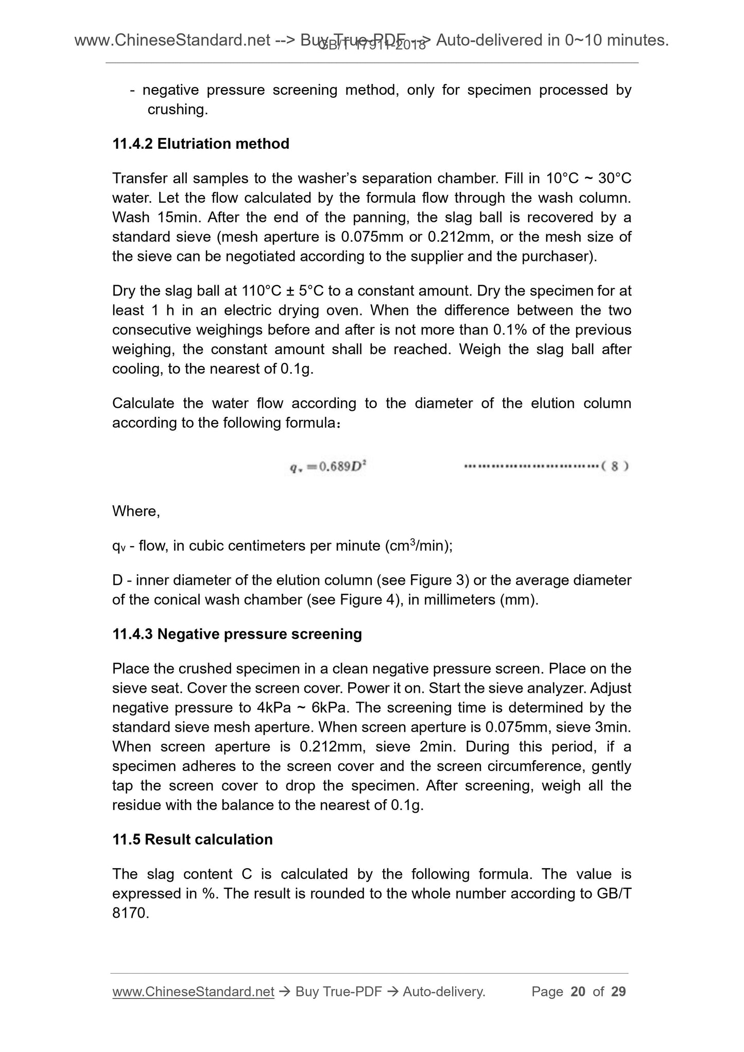
Calculate the water flow according to the diameter of the elution column
according to the following formula.
Where,
qv - flow, in cubic centimeters per minute (cm3/min);
D - inner diameter of the elution column (see Figure 3) or the average diameter
of the conical wash chamber (see Figure 4), in millimeters (mm).
11.4.3 Negative pressure screening
Place the crushed specimen in a clean negative pressure screen. Place on the
sieve seat. Cover the screen cover. Power it on. Start the sieve analyzer. Adjust
negative pressure to 4kPa ~ 6kPa. The screening time is determined by the
standard sieve mesh aperture. When screen aperture is 0.075mm, sieve 3min.
When screen aperture is 0.212mm, sieve 2min. During this period, if a
specimen adheres to the screen cover and the screen circumference, gently
tap the screen cover to drop the specimen. After screening, weigh all the
residue with the balance to the nearest of 0.1g.
11.5 Result ca...
Get Quotation: Click GB/T 17911-2018 (Self-service in 1-minute)
Historical versions (Master-website): GB/T 17911-2018
Preview True-PDF (Reload/Scroll-down if blank)
GB/T 17911-2018: Methods of test for refractory fibre products
GB/T 17911-2018
GB
NATIONAL STANDARD OF THE
PEOPLE’S REPUBLIC OF CHINA
ICS 81.080
Q 47
Replacing GB/T 17911-2006
Methods of test for refractory fibre product
(ISO 10635.1999, Refractory products –
Methods of test for ceramic fibre products, MOD)
ISSUED ON. MAY 14, 2018
IMPLEMENTED ON. APRIL 01, 2019
Issued by. State Administration for Market Regulation;
Standardization Administration Committee.
Table of Contents
Foreword ... 3
1 Scope ... 5
2 Normative references ... 5
3 Terms and definitions ... 5
4 Specimen preparation ... 5
5 Thickness measurement ... 7
6 Measurement of bulk density ... 8
7 Measurement of resilience ... 9
8 Measurement of heating permanent line change ... 10
9 Measurement of thermal conductivity ... 13
10 Measurement of tensile strength ... 17
11 Measurement of slag content ... 18
12 Test report ... 21
Annex A (informative) Comparison on sub-clause number between this
Standard and ISO 10635.1999 ... 26
Annex B (informative) Technical differences between this Standard and ISO
10635.1999 as well as the reasons ... 27
Annex C (informative) Calculation of thermal conductivity at actual temperature
of each point in the sample ... 29
Foreword
This Standard was drafted in accordance with the rules given in GB/T 1.1-2009.
This Standard replaces GB/T 17911-2006 "Refractory products - Methods of
test for ceramic fibre products". Compared with GB/T 17911-2006, the main
technical changes are as follows.
- modified the standard's name;
- added Clause 3; used GB/T 18930 as reference; deleted the definitions of
resilience, thermal conductivity, tensile strength and slag content in other
sub-clauses;
- modified the provisions on dry sample in 6.3.2;
- modified formula (3), consistent with international standard expression;
- modified the unit of tensile strength as kPa, the units of sample thickness
and width as mm; modified formula (7);
- added negative pressure screening as test method for slag content;
different sieve apertures can be selected as needed for the determination
of the content of the slag.
This Standard uses redrafting method to modify and adopt ISO 10635.1999
"Refractory products - Methods of test for ceramic fibre products".
Compared with ISO 10635.1999, this Standard has modifications on structure.
Annex A shows the comparison list on sub-clause number between this
Standard and ISO 10635.1999.
There are technical differences between this Standard and ISO 10635.1999.
The sub-clauses these differences involved have been marked with vertical line
(|) at the outer margin. Annex B lists the technical differences between this
Standard and ISO 10635.1999 as well as reasons.
Attention is drawn to the possibility that some of the elements of this Standard
may be the subject of patent rights. The issuing authority shall not be held
responsible for identifying any or all such patent rights.
This Standard was proposed by and shall be under the jurisdiction of National
Technical Committee on Refractory of Standardization Administration of China
(SAC/TC 193).
Methods of test for refractory fibre product
1 Scope
This Standard specifies the test methods for thickness, bulk density, resilience,
permanent line change, thermal conductivity, tensile strength and slag content
of refractory fibre.
This Standard is applicable to refractory fiber cotton, carpet, felt, woven, board,
paper and preforms; not applicable to products delivered in a wet state.
2 Normative references
The following referenced documents are indispensable for the application of
this document. For dated references, only the edition cited applies. For undated
references, the latest edition of the referenced document (including any
amendments) applies.
GB/T 6003.1, Test sieves - Technical requirements and testing - Part 1. Test
sieves of metal wire cloth (GB/T 6003.1-2012, ISO 3310-1.2000, MOD)
GB/T 8170, Rules of rounding off for numerical values and expression and
judgement of limiting values
GB/T 18930, Terminology for refractories
JJG 139, Tension, Compression and Universal Testing Machines
3 Terms and definitions
For the purposes of this document, the terms and definitions defined in GB/T
18930 apply.
4 Specimen preparation
The test items of the products shall be agreed by the relevant parties. The size
and quantity of the specimen shall comply with the requirements of Table 1.
Remove rolled material from the surrounding pressurized part. Then, make its
length perpendicularly across the entire width and cut a sample of sufficient
quantity for different test items. For non-rolled material, there shall be enough
5 Thickness measurement
5.1 Principle
The thickness of the product is measured under specified compressive stress.
The compressive stress is determined by the nominal bulk density of the
product. There are two methods of measurement. the comparison method (see
5.3.1) and the acupuncture method (see 5.3.2). The comparison method is an
arbitration method and is the only method for refractory fiber paper.
5.2 Specimen
Prepare specimen according to Clause 4.
5.3 Methods
5.3.1 Comparison method
5.3.1.1 Equipment
Thickness gauge consists of a reference plate and a comparator with a metal
disc. The disc diameter is 75mm ± 1mm. The disc shall be capable of applying
a compressive stress of 350Pa ± 7Pa to a product having a nominal bulk density
of < 96kg/m3. For products with a nominal volume density of ≥ 96kg/m3, a
compressive stress of 725Pa±15Pa shall be applied.
5.3.1.2 Test steps
Sweep the reference board clean. Place the disc on it. When the two are in full
contact, the comparator reads zero.
Smoothly lift the disc. Put the specimen on the reference board. Slowly put
down the disc. Record the reading, to the nearest of 0.1mm.
5.3.2 Acupuncture
5.3.2.1 Equipment
Needle type thickness gauge consists of a metal disc with a frame and a ruler
with a needle, as shown in Figure 1. The ruler has marks. The diameter of the
disc is 75mm ± 1mm. The diameter of the needle is 3mm ± 0.2mm. The disc
shall be capable of applying a compressive stress of 350Pa ± 7Pa to a product
having a nominal bulk density of < 96kg/m3. For products with a nominal volume
density of ≥ 96kg/m3, a compressive stress of 725Pa ± 15Pa shall be applied.
5.3.2.2 Test steps
Place the sample flat on the flat glass. Gently place the disc of the needle type
Keep the specimen at the specified temperature for a certain period of time.
Indicate the change of the permanent line of the specimen in terms of the ratio
of the difference between the original size and the heated size between the
platinum wires inserted on the surface of the specimen to the original size.
8.2 Equipment
8.2.1 Heating furnace, shall be an oxidizing atmosphere and meet the relevant
requirements of 8.4.3.
8.2.2 Measuring device, using optical instruments, such as a tool microscope
with a graduation value of 0.01 mm; or a vernier caliper with an accuracy 0.05
mm.
8.2.3 Thermocouple, at least two.
8.3 Specimen
8.3.1 Prepare specimen according to Clause 4.
8.3.2 Dry specimen according to 6.3.2.
8.4 Test steps
8.4.1 Specimen preparation
On the diagonal line of 100mm×100mm on the surface of each specimen, insert
4 platinum wires at the edge from 10mm ~ 15mm for marking. The spacing is
about 75 mm.
Platinum wire diameter is about 0.5 mm. The length shall be such that it can be
inserted at least 3/4 of the thickness of the specimen and has a protruding
surface of 1 mm to 2 mm.
NOTE. For plates and preforms, color markings (such as chromium oxide) can be used
instead of platinum wire.
8.4.2 Measurement
Measure the distance between the platinum wires parallel to the edge of the
specimen. Measure with optical instruments, to the nearest of 0.05 mm, as an
arbitration method. Measure with vernier caliper, to the nearest of 0.1 mm. The
measurement method shall be indicated in the test report.
8.4.3 Heating
8.4.3.1 Specimen placement
Place the specimen flat on a pad cut from the same material. The pad can only
The central calorimeter and the inner protection device are respectively
equipped with a water inlet and a water outlet. The inlet and outlet shall be
positioned to avoid heat transfer between the central calorimeter and the
internal protection device. Inlet water temperature shall be within room
temperature +3°C ~ -1°C. The temperature change of the inlet water shall not
exceed 0.5°C/h. The inlet pressure shall be constant. The water pressure shall
not change by more than 1%.
9.2.1.3 Measuring device of water temperature
It shall be able to measure the temperature difference between the inlet and
outlet, to the nearest of 0.05°C.
9.2.2 Electric heating furnace
It shall ensure that the temperature distribution is uniform over the entire surface
of the specimen. The temperature control device shall be able to keep the
temperature constant. The fluctuation range does not exceed ±10°C.
Heating rate shall meet the requirements of Table 2.
9.3 Specimen
9.3.1 Prepare specimen according to Clause 4.
9.3.2 Dry specimen according to 6.3.2.
9.4 Test steps
9.4.1 Specimen installation
For each layer of specimens, use insulating bricks to prepare 4 pillars with a
diameter of 17mm ± 0.5mm. Its height shall be 9/10 ~ 1 of specimen thickness.
Pierce the holes with a diameter same as the pillar on 4 corners of each layer
of specimens. Load the pillars into the holes. The position of the holes on each
layer of specimens shall be the same.
Install the first thermocouple in the center of the center calorimeter. Then install
the first layer specimen. Press a piece of wood or other tool with the same
length and width as the specimen to the top of the pillar to bring the specimen
into close contact with the calorimeter. Take out the board. Place the second
thermocouple on the center of the first layer of the specimen, directly above the
first thermocouple. So on and so forth, install the second layer specimen and
the third thermocouple until the required number of layers. Use a silicon carbide
plate of the same length and width as the specimen to press on the last
specimen and thermocouple. The silicon carbide plate remains in contact with
the layer of the specimen and the thermocouple above it during the entire test
period.
F - maximum tensile force when the specimen breaks, in Newtons (N);
w - original width of the tensioned portion of the specimen, in millimeters (mm);
t - original thickness of the tensioned portion of the specimen, in millimeters
(mm).
10.6 Test report of this item
Report the relationship between the length direction of the specimen and the
manufacturing direction of the product and the average of the test results of the
five samples as required by Clause 12.
11 Measurement of slag content
11.1 Principle
Burn off organic matter that may be present in the fiber product and embrittle
the fiber. Separate fibers from slag balls by pressurization and agitation.
Recycle the slag ball.
11.2 Equipment
11.2.1 Heating furnace.
11.2.2 Balance, graduation value of 0.1 g.
11.2.3 Pressure cylinder, inner diameter of 50mm ± 5mm, built-in quenched
steel piston, leaving 0.15mm ~ 0.20mm clearance.
11.2.4 Pressure testing machine, measuring range of 25 kN.
11.2.5 Glass washer, including separation chamber, panning column, and water
at a constant flow rate. Washing column diameter is 29mm ~ 76mm. The entire
device volume is ≥ 0.75dm3 (see Figure 3 and Figure 4 for an example).
11.2.6 Agitator, including a glass crucible with a volume of 1L, speed ≥
15000r/min.
11.2.7 Standard sieve, which shall meet the requirements of GB/T 6003.1.
11.2.8 Negative pressure sieve analyzer consisting of sieve seat, negative
pressure screen, negative pressure source and dust collector, of which the
sieve base consists of an air nozzle with a rotational speed of (30 ± 2) r/min, a
negative pressure gauge, a control panel, a micromotor and a housing; the
negative pressure of the sieve analyzer can be adjusted from 0kPa to 10kPa
(see Figure 5 for the screen of the negative pressure sieve analyzer).
- negative pressure screening method, only for specimen processed by
crushing.
11.4.2 Elutriation method
Transfer all samples to the washer’s separation chamber. Fill in 10°C ~ 30°C
water. Let the flow calculated by the formula flow through the wash column.
Wash 15min. After the end of the panning, the slag ball is recovered by a
standard sieve (mesh aperture is 0.075mm or 0.212mm, or the mesh size of
the sieve can be negotiated according to the supplier and the purchaser).
Dry the slag ball at 110°C ± 5°C to a constant amount. Dry the specimen for at
least 1 h in an electric drying oven. When the difference between the two
consecutive weighings before and after is not more than 0.1% of the previous
weighing, the constant amount shall be reached. Weigh the slag ball after
cooling, to the nearest of 0.1g.
Calculate the water flow according to the diameter of the elution column
according to the following formula.
Where,
qv - flow, in cubic centimeters per minute (cm3/min);
D - inner diameter of the elution column (see Figure 3) or the average diameter
of the conical wash chamber (see Figure 4), in millimeters (mm).
11.4.3 Negative pressure screening
Place the crushed specimen in a clean negative pressure screen. Place on the
sieve seat. Cover the screen cover. Power it on. Start the sieve analyzer. Adjust
negative pressure to 4kPa ~ 6kPa. The screening time is determined by the
standard sieve mesh aperture. When screen aperture is 0.075mm, sieve 3min.
When screen aperture is 0.212mm, sieve 2min. During this period, if a
specimen adheres to the screen cover and the screen circumference, gently
tap the screen cover to drop the specimen. After screening, weigh all the
residue with the balance to the nearest of 0.1g.
11.5 Result ca...
Share