1
/
of
11
PayPal, credit cards. Download editable-PDF and invoice in 1 second!
GB/T 19484.1-2013 English PDF (GBT19484.1-2013)
GB/T 19484.1-2013 English PDF (GBT19484.1-2013)
Regular price
$305.00 USD
Regular price
Sale price
$305.00 USD
Unit price
/
per
Shipping calculated at checkout.
Couldn't load pickup availability
Delivery: 3 seconds. Download true-PDF + Invoice.
Get QUOTATION in 1-minute: Click GB/T 19484.1-2013
Historical versions: GB/T 19484.1-2013
Preview True-PDF (Reload/Scroll if blank)
GB/T 19484.1-2013: Requirements and measurement methods of electromagnetic compatibility for 800MHz/2GHz cdma2000 digital cellular mobile telecommunications system -- Part 1: User equipment and ancillary equipment
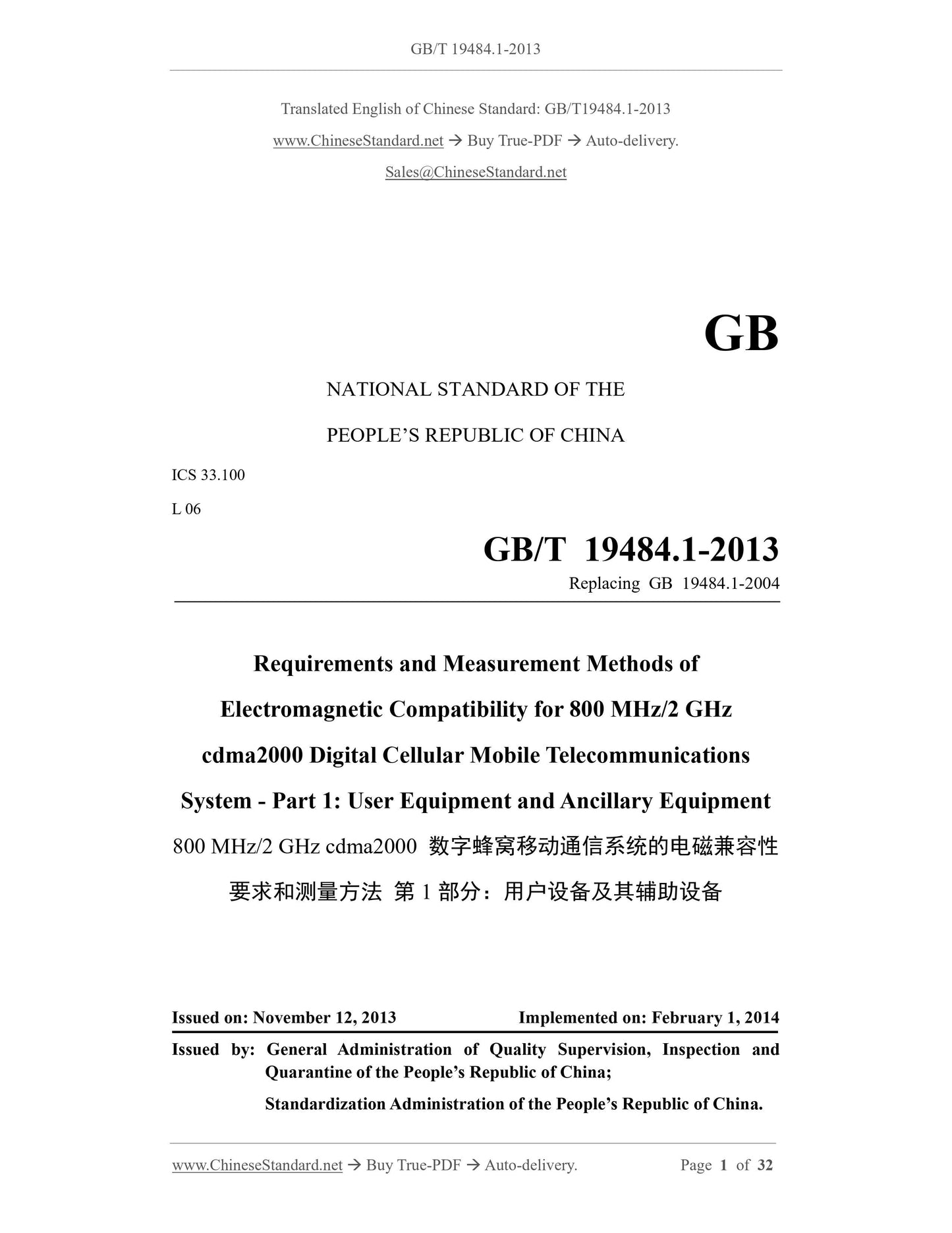
GB/T 19484.1-2013
GB
NATIONAL STANDARD OF THE
PEOPLE’S REPUBLIC OF CHINA
ICS 33.100
L 06
Replacing GB 19484.1-2004
Requirements and Measurement Methods of
Electromagnetic Compatibility for 800 MHz/2 GHz
cdma2000 Digital Cellular Mobile Telecommunications
System - Part 1: User Equipment and Ancillary Equipment
ISSUED ON: NOVEMBER 12, 2013
IMPLEMENTED ON: FEBRUARY 1, 2014
Issued by: General Administration of Quality Supervision, Inspection and
Quarantine of the People’s Republic of China;
Standardization Administration of the People’s Republic of China.
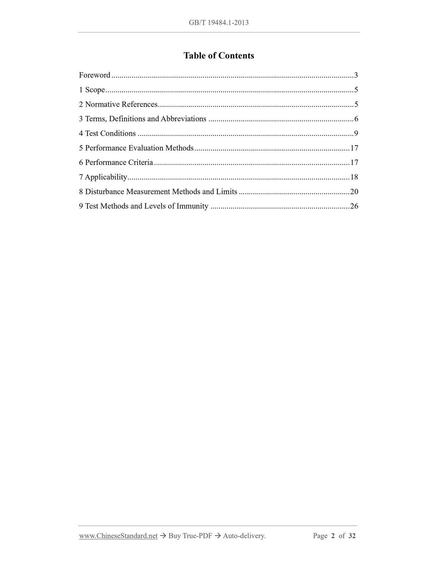
Table of Contents
Foreword ... 3
1 Scope ... 5
2 Normative References ... 5
3 Terms, Definitions and Abbreviations ... 6
4 Test Conditions ... 9
5 Performance Evaluation Methods ... 17
6 Performance Criteria ... 17
7 Applicability ... 18
8 Disturbance Measurement Methods and Limits ... 20
9 Test Methods and Levels of Immunity ... 26
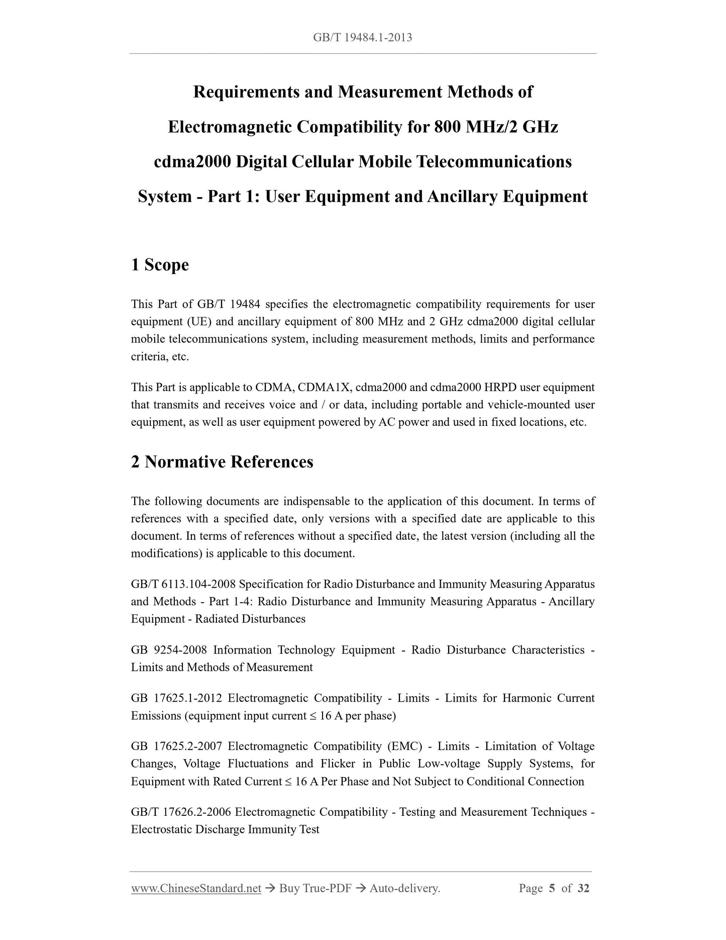
Requirements and Measurement Methods of
Electromagnetic Compatibility for 800 MHz/2 GHz
cdma2000 Digital Cellular Mobile Telecommunications
System - Part 1: User Equipment and Ancillary Equipment
1 Scope
This Part of GB/T 19484 specifies the electromagnetic compatibility requirements for user
equipment (UE) and ancillary equipment of 800 MHz and 2 GHz cdma2000 digital cellular
mobile telecommunications system, including measurement methods, limits and performance
criteria, etc.
This Part is applicable to CDMA, CDMA1X, cdma2000 and cdma2000 HRPD user equipment
that transmits and receives voice and / or data, including portable and vehicle-mounted user
equipment, as well as user equipment powered by AC power and used in fixed locations, etc.
2 Normative References
The following documents are indispensable to the application of this document. In terms of
references with a specified date, only versions with a specified date are applicable to this
document. In terms of references without a specified date, the latest version (including all the
modifications) is applicable to this document.
GB/T 6113.104-2008 Specification for Radio Disturbance and Immunity Measuring Apparatus
and Methods - Part 1-4: Radio Disturbance and Immunity Measuring Apparatus - Ancillary
Equipment - Radiated Disturbances
GB 9254-2008 Information Technology Equipment - Radio Disturbance Characteristics -
Limits and Methods of Measurement
GB 17625.1-2012 Electromagnetic Compatibility - Limits - Limits for Harmonic Current
Emissions (equipment input current 16 A per phase)
GB 17625.2-2007 Electromagnetic Compatibility (EMC) - Limits - Limitation of Voltage
Changes, Voltage Fluctuations and Flicker in Public Low-voltage Supply Systems, for
Equipment with Rated Current 16 A Per Phase and Not Subject to Conditional Connection
GB/T 17626.2-2006 Electromagnetic Compatibility - Testing and Measurement Techniques -
Electrostatic Discharge Immunity Test
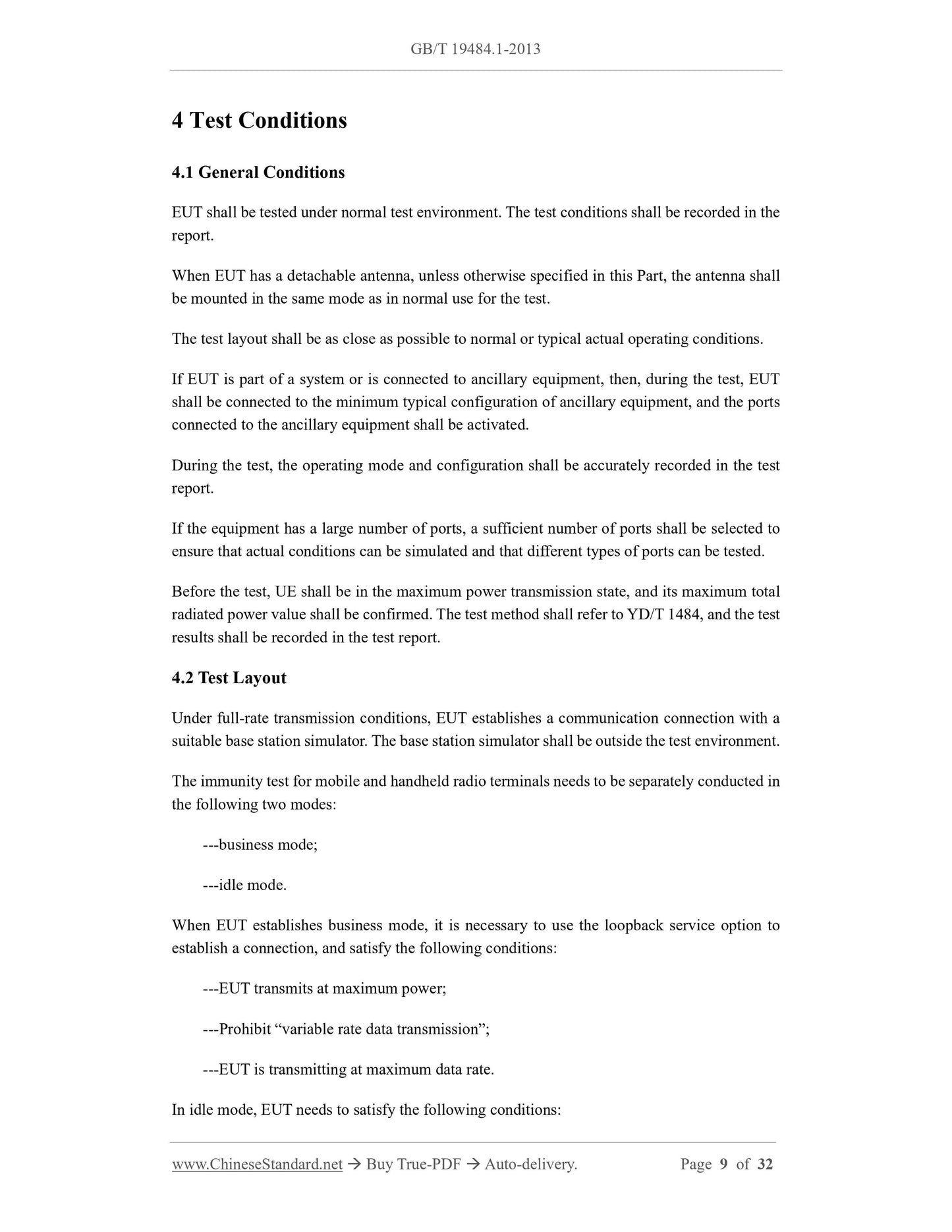
4 Test Conditions
4.1 General Conditions
EUT shall be tested under normal test environment. The test conditions shall be recorded in the
report.
When EUT has a detachable antenna, unless otherwise specified in this Part, the antenna shall
be mounted in the same mode as in normal use for the test.
The test layout shall be as close as possible to normal or typical actual operating conditions.
If EUT is part of a system or is connected to ancillary equipment, then, during the test, EUT
shall be connected to the minimum typical configuration of ancillary equipment, and the ports
connected to the ancillary equipment shall be activated.
During the test, the operating mode and configuration shall be accurately recorded in the test
report.
If the equipment has a large number of ports, a sufficient number of ports shall be selected to
ensure that actual conditions can be simulated and that different types of ports can be tested.
Before the test, UE shall be in the maximum power transmission state, and its maximum total
radiated power value shall be confirmed. The test method shall refer to YD/T 1484, and the test
results shall be recorded in the test report.
4.2 Test Layout
Under full-rate transmission conditions, EUT establishes a communication connection with a
suitable base station simulator. The base station simulator shall be outside the test environment.
The immunity test for mobile and handheld radio terminals needs to be separately conducted in
the following two modes:
---business mode;
---idle mode.
When EUT establishes business mode, it is necessary to use the loopback service option to
establish a connection, and satisfy the following conditions:
---EUT transmits at maximum power;
---Prohibit “variable rate data transmission”;
---EUT is transmitting at maximum data rate.
In idle mode, EUT needs to satisfy the following conditions:
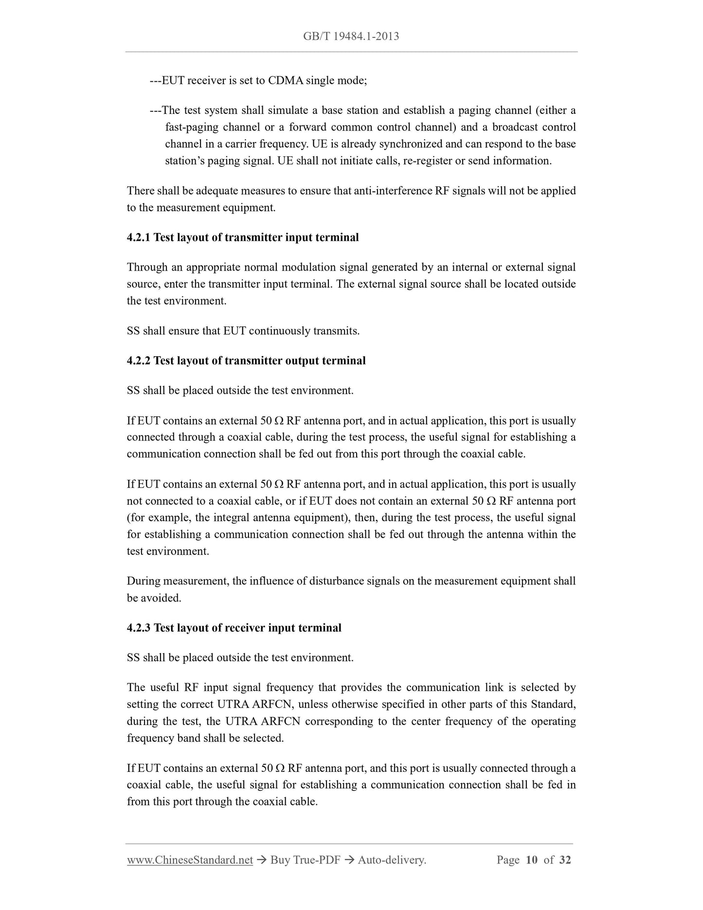
---EUT receiver is set to CDMA single mode;
---The test system shall simulate a base station and establish a paging channel (either a
fast-paging channel or a forward common control channel) and a broadcast control
channel in a carrier frequency. UE is already synchronized and can respond to the base
station’s paging signal. UE shall not initiate calls, re-register or send information.
There shall be adequate measures to ensure that anti-interference RF signals will not be applied
to the measurement equipment.
4.2.1 Test layout of transmitter input terminal
Through an appropriate normal modulation signal generated by an internal or external signal
source, enter the transmitter input terminal. The external signal source shall be located outside
the test environment.
SS shall ensure that EUT continuously transmits.
4.2.2 Test layout of transmitter output terminal
SS shall be placed outside the test environment.
If EUT contains an external 50 RF antenna port, and in actual application, this port is usually
connected through a coaxial cable, during the test process, the useful signal for establishing a
communication connection shall be fed out from this port through the coaxial cable.
If EUT contains an external 50 RF antenna port, and in actual application, this port is usually
not connected to a coaxial cable, or if EUT does not contain an external 50 RF antenna port
(for example, the integral antenna equipment), then, during the test process, the useful signal
for establishing a communication connection shall be fed out through the antenna within the
test environment.
During measurement, the influence of disturbance signals on the measurement equipment shall
be avoided.
4.2.3 Test layout of receiver input terminal
SS shall be placed outside the test environment.
The useful RF input signal frequency that provides the communication link is selected by
setting the correct UTRA ARFCN, unless otherwise specified in other parts of this Standard,
during the test, the UTRA ARFCN corresponding to the center frequency of the operating
frequency band shall be selected.
If EUT contains an external 50 RF antenna port, and this port is usually connected through a
coaxial cable, the useful signal for establishing a communication connection shall be fed in
from this port through the coaxial cable.
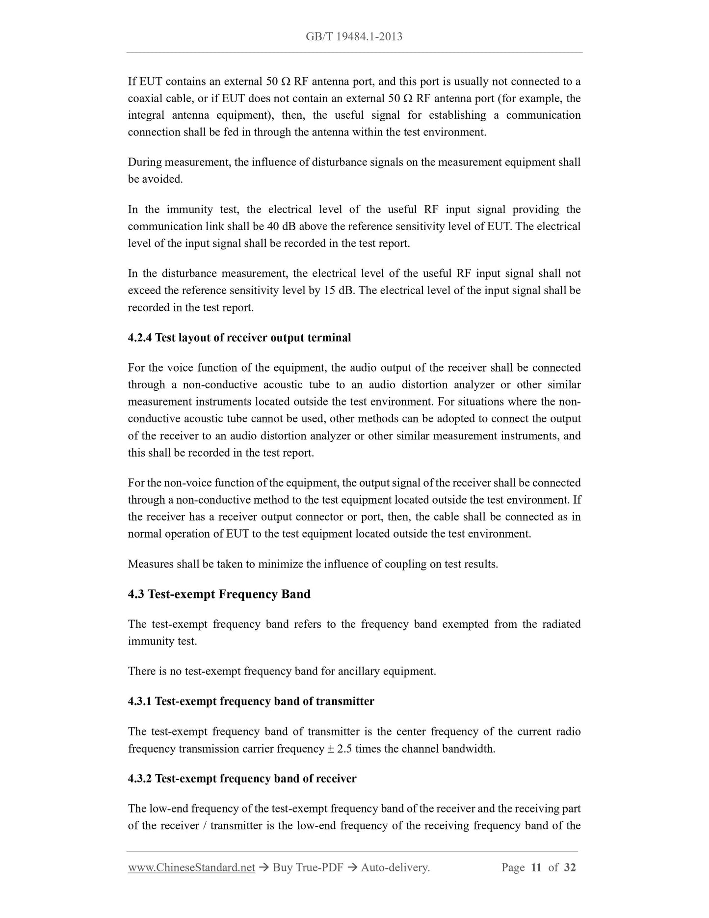
If EUT contains an external 50 RF antenna port, and this port is usually not connected to a
coaxial cable, or if EUT does not contain an external 50 RF antenna port (for example, the
integral antenna equipment), then, the useful signal for establishing a communication
connection shall be fed in through the antenna within the test environment.
...
Share
