1
/
of
10
www.ChineseStandard.us -- Field Test Asia Pte. Ltd.
GB/T 20834-2024 English PDF (GB/T20834-2024)
GB/T 20834-2024 English PDF (GB/T20834-2024)
Regular price
$275.00
Regular price
Sale price
$275.00
Unit price
/
per
Shipping calculated at checkout.
Couldn't load pickup availability
GB/T 20834-2024: Technical requirements for motor-generator
Delivery: 9 seconds. Download (& Email) true-PDF + Invoice.
Get Quotation: Click GB/T 20834-2024 (Self-service in 1-minute)
Historical versions (Master-website): GB/T 20834-2024
Preview True-PDF (Reload/Scroll-down if blank)
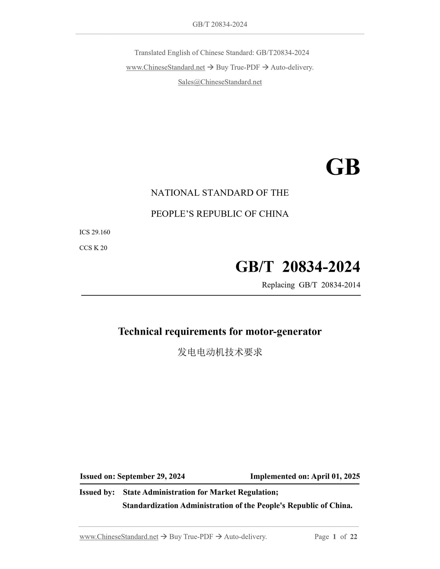
GB/T 20834-2024
GB
NATIONAL STANDARD OF THE
PEOPLE’S REPUBLIC OF CHINA
ICS 29.160
CCS K 20
Replacing GB/T 20834-2014
Technical requirements for motor-generator
ISSUED ON: SEPTEMBER 29, 2024
IMPLEMENTED ON: APRIL 01, 2025
Issued by: State Administration for Market Regulation;
Standardization Administration of the People's Republic of China.
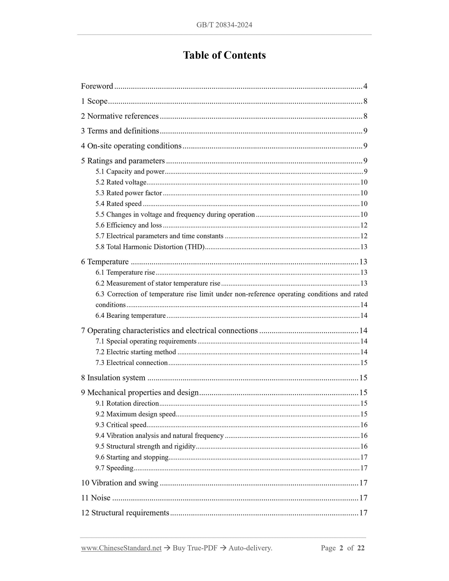
Table of Contents
Foreword ... 4
1 Scope ... 8
2 Normative references ... 8
3 Terms and definitions ... 9
4 On-site operating conditions ... 9
5 Ratings and parameters ... 9
5.1 Capacity and power ... 9
5.2 Rated voltage ... 10
5.3 Rated power factor ... 10
5.4 Rated speed ... 10
5.5 Changes in voltage and frequency during operation ... 10
5.6 Efficiency and loss ... 12
5.7 Electrical parameters and time constants ... 12
5.8 Total Harmonic Distortion (THD) ... 13
6 Temperature ... 13
6.1 Temperature rise ... 13
6.2 Measurement of stator temperature rise ... 13
6.3 Correction of temperature rise limit under non-reference operating conditions and rated
conditions ... 14
6.4 Bearing temperature ... 14
7 Operating characteristics and electrical connections ... 14
7.1 Special operating requirements ... 14
7.2 Electric starting method ... 14
7.3 Electrical connection ... 15
8 Insulation system ... 15
9 Mechanical properties and design ... 15
9.1 Rotation direction ... 15
9.2 Maximum design speed ... 15
9.3 Critical speed ... 16
9.4 Vibration analysis and natural frequency ... 16
9.5 Structural strength and rigidity ... 16
9.6 Starting and stopping... 17
9.7 Speeding ... 17
10 Vibration and swing ... 17
11 Noise ... 17
12 Structural requirements ... 17
Technical requirements for motor-generator
1 Scope
This document specifies the overall technical requirements for generator motors and
their ancillary equipment, as well as requirements for product identification, material
and component storage, factory and field testing, supply and trial operation, and
warranty period.
This document is applicable to three-phase, 50 Hz, reversible salient-pole synchronous
generator motors (hereinafter referred to as "generator motors") directly connected to
pump-turbines with a rated capacity of 100 MVA and above. For units with a rated
capacity of less than 100 MVA or a frequency of 60 Hz, this document can be used as
a reference.
2 Normative references
The following referenced documents are indispensable for the application of this
document. For dated references, only the edition cited applies. For undated references,
the latest edition of the referenced document (including any amendments) applies.
GB/T 755, Rotating electrical machines -- Rating and performance
GB/T 2900.25, Electrotechnical terminology -- Rotating electrical machines
GB/T 5321, Measurement of loss and efficiency for electrical machine by the
calorimetric method
GB/T 7894-2023, Fundamental technical requirements for hydro generators
GB/T 11805, General specifications of automatic control components (devices) and
their related system for hydro-turbine generating sets
GB/T 18482, Specification for start-up test of reversible pumped-storage units
GB/T 25442, Standard methods for determining losses and efficiency of rotation
electrical machines from tests (excluding machines for traction vehicles)
GB/T 36550, Basic terminology of pumped storage power station
GB 50084, Code of design for sprinkler systems
GB 50193, Code of design for carbon dioxide fire extinguishing systems
NB/T 47004.1, Plate heat exchangers - Part 1: Plate-and-frame heat exchangers
3 Terms and definitions
For the purposes of this document, the terms and definitions defined in GB/T 2900.25,
GB/T 755, GB/T 7894 and GB/T 36550 apply.
4 On-site operating conditions
Unless otherwise specified, the generator motor shall be able to operate continuously at
rated speed under the following environmental conditions:
a) Altitude shall not exceed 1000 m;
b) Cooling air temperature shall not exceed 40℃;
c) Inlet water temperature of air cooler and oil cooler shall not be higher than 30℃
and not lower than 5℃;
d) Relative humidity shall not exceed 85%;
e) Meet the requirements of local earthquake acceleration. The purchaser shall
provide the requirements of horizontal and vertical acceleration values according
to the geographical conditions of the location.
For operating environments that are different from the above requirements, the on-site
operating conditions shall be determined by negotiation between the supplier and the
purchaser.
5 Ratings and parameters
5.1 Capacity and power
5.1.1 The rated capacity under power generation conditions refers to the apparent power
output at the rated frequency, rated voltage and rated power factor, and the unit is MVA.
5.1.2 The rated power under electric working condition refers to the mechanical power
output on the shaft under rated frequency, rated voltage and rated power factor, and the
unit is MW.
5.1.3 The capacity/power of the generator motor shall match the turbine operating
output power of the pump-turbine and the maximum input power of the pump operating
condition.
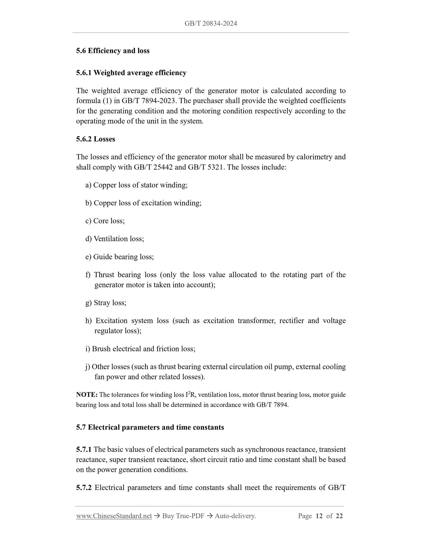
5.6 Efficiency and loss
5.6.1 Weighted average efficiency
The weighted average efficiency of the generator motor is calculated according to
formula (1) in GB/T 7894-2023. The purchaser shall provide the weighted coefficients
for the generating condition and the motoring condition respectively according to the
operating mode of the unit in the system.
5.6.2 Losses
The losses and efficiency of the generator motor shall be measured by calorimetry and
shall comply with GB/T 25442 and GB/T 5321. The losses include:
a) Copper loss of stator winding;
b) Copper loss of excitation winding;
c) Core loss;
d) Ventilation loss;
e) Guide bearing loss;
f) Thrust bearing loss (only the loss value allocated to the rotating part of the
generator motor is taken into account);
g) Stray loss;
h) Excitation system loss (such as excitation transformer, rectifier and voltage
regulator loss);
i) Brush electrical and friction loss;
j) Other losses (such as thrust bearing external circulation oil pump, external cooling
fan power and other related losses).
NOTE: The tolerances for winding loss I2R, ventilation loss, motor thrust bearing loss, motor guide
bearing loss and total loss shall be determined in accordance with GB/T 7894.
5.7 Electrical parameters and time constants
5.7.1 The basic values of electrical parameters such as synchronous reactance, transient
reactance, super transient reactance, short circuit ratio and time constant shall be based
on the power generation conditions.
5.7.2 Electrical parameters and time constants shall meet the requirements of GB/T
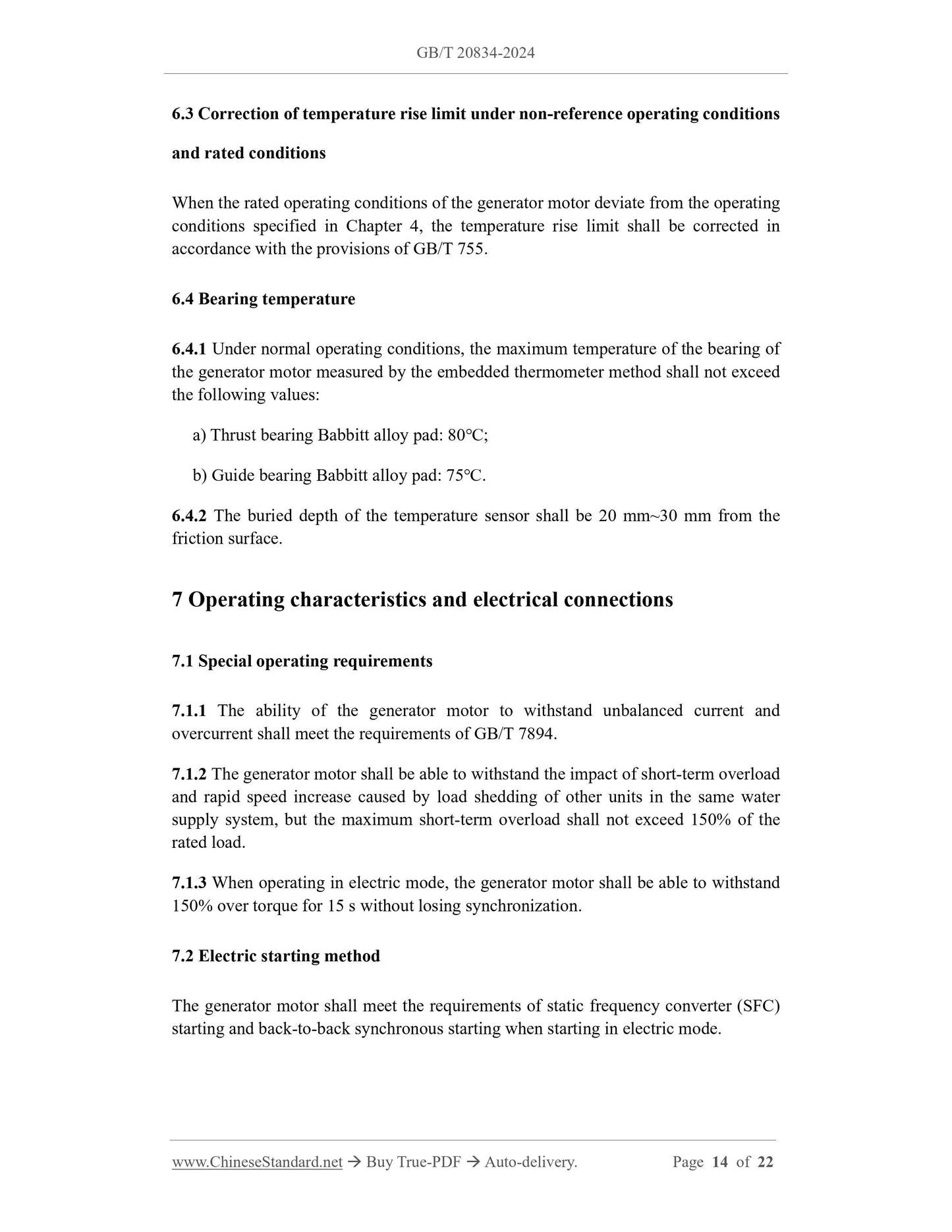
6.3 Correction of temperature rise limit under non-reference operating conditions
and rated conditions
When the rated operating conditions of the generator motor deviate from the operating
conditions specified in Chapter 4, the temperature rise limit shall be corrected in
accordance with the provisions of GB/T 755.
6.4 Bearing temperature
6.4.1 Under normal operating conditions, the maximum temperature of the bearing of
the generator motor measured by the embedded thermometer method shall not exceed
the following values:
a) Thrust bearing Babbitt alloy pad: 80℃;
b) Guide bearing Babbitt alloy pad: 75℃.
6.4.2 The buried depth of the temperature sensor shall be 20 mm~30 mm from the
friction surface.
7 Operating characteristics and electrical connections
7.1 Special operating requirements
7.1.1 The ability of the generator motor to withstand unbalanced current and
overcurrent shall meet the requirements of GB/T 7894.
7.1.2 The generator motor shall be able to withstand the impact of short-term overload
and rapid speed increase caused by load shedding of other units in the same water
supply system, but the maximum short-term overload shall not exceed 150% of the
rated load.
7.1.3 When operating in electric mode, the generator motor shall be able to withstand
150% over torque for 15 s without losing synchronization.
7.2 Electric starting method
The generator motor shall meet the requirements of static frequency converter (SFC)
starting and back-to-back synchronous starting when starting in electric mode.
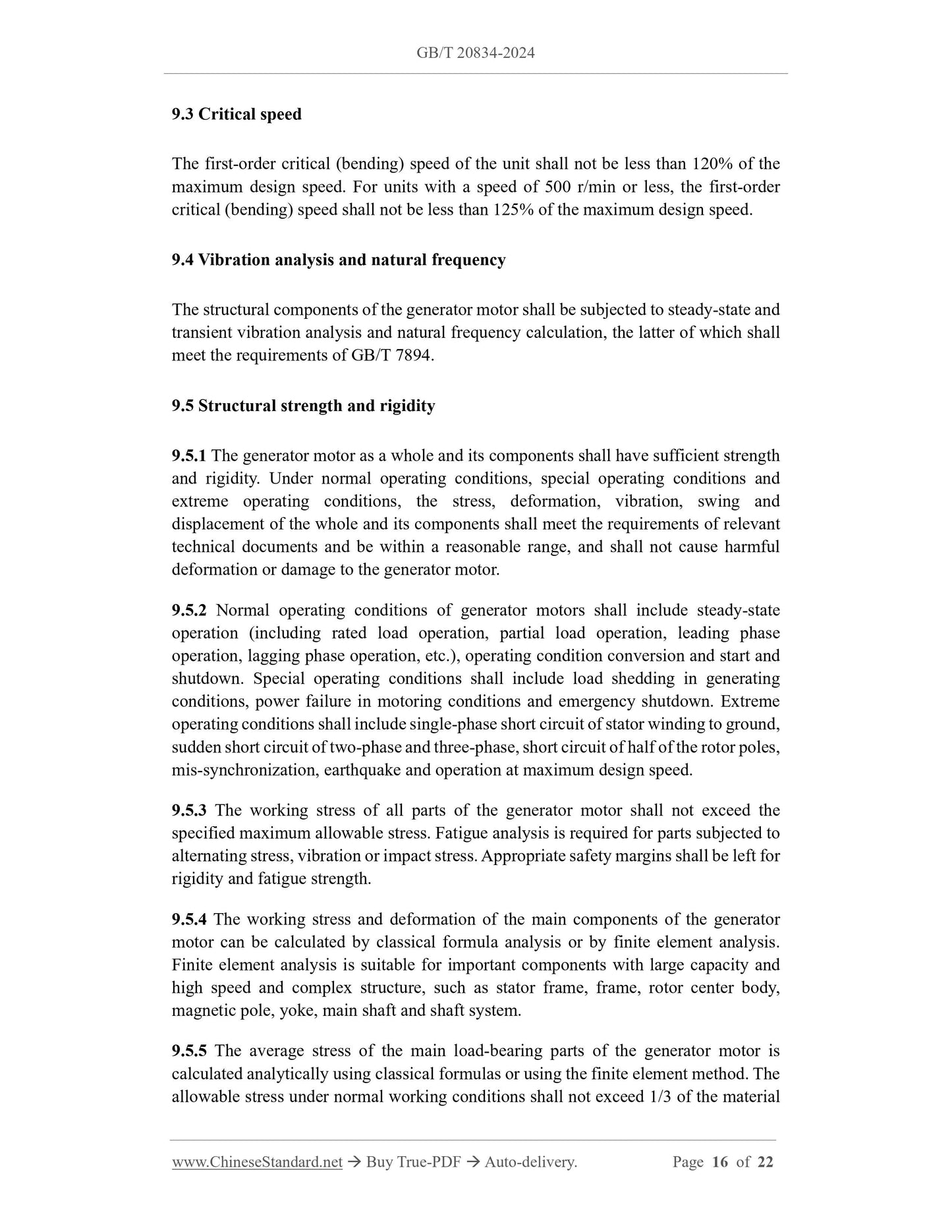
9.3 Critical speed
The first-order critical (bending) speed of the unit shall not be less than 120% of the
maximum design speed. For units with a speed of 500 r/min or less, the first-order
critical (bending) speed shall not be less than 125% of the maximum design speed.
9.4 Vibration analysis and natural frequency
The structural components of the generator motor shall be subjected to steady-state and
transient vibration analysis and natural frequency calculation, the latter of which shall
meet the requirements of GB/T 7894.
9.5 Structural strength and rigidity
9.5.1 The generator motor as a whole and its components shall have sufficient strength
and rigidity. Under normal operating conditions, special operating conditions and
extreme operating conditions, the stress, deformation, vibration, swing and
displacement of the whole and its components shall meet the requirements of relevant
technical documents and be within a reasonable range, and shall not cause harmful
deformation or damage to the generator motor.
9.5.2 Normal operating conditions of generator motors shall include steady-state
operation (including rated load operation, partial load operation, leading phase
operation, lagging phase operation, etc.), operating condition conversion and start and
shutdown. Special operating conditions shall include load shedding in generating
conditions, power failure in motoring conditions and emergency shutdown. Extreme
operating conditions shall include single-phase short circuit of stator winding to ground,
sudden short circuit of two-phase and three-phase, short circuit of half of the rotor poles,
mis-synchronization, earthquake and operation at maximum design speed.
9.5.3 The working stress of all parts of the generator motor shall not exceed the
specified maximum allowable stress. Fatigue analysis is required for parts subjected to
alternating stress, vibration or impact stress. Appropriate safety margins shall be left for
rigidity and fatigue strength.
9.5.4 The working stress and deformation of the main components of the generator
motor can be calculated by classical formula analysis or by finite element analysis.
Finite element analysis is suitable for important components with large capacity and
high speed and complex structure, such as stator frame, frame, rotor center body,
magnetic pole, yoke, main shaft and shaft system.
9.5.5 The average stress of the main load-bearing parts of the generator motor is
calculated analytically using classical formulas or using the finite element method. The
allowable stress under normal working conditions shall not exceed 1/3 of the material
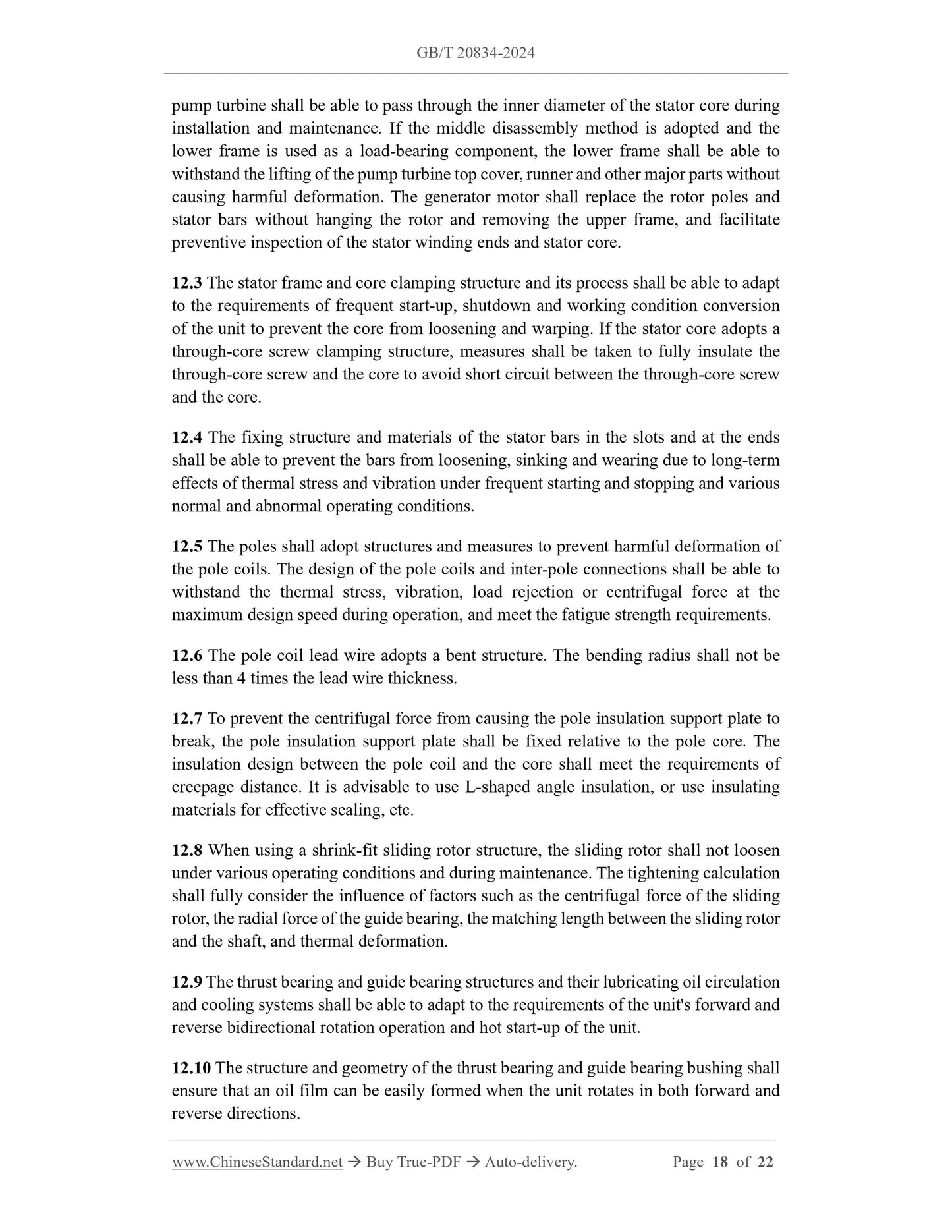
pump turbine shall be able to pass through the inner diameter of the stator core during
installation and maintenance. If the middle disassembly method is adopted and the
lower frame is used as a load-bearing component, the lower frame shall be able to
withstand the lifting of the pump turbine top cover, runner and other major parts without
causing harmful deformation. The generator motor shall replace the rotor poles and
stator bars without hanging the rotor and removing the upper frame, and facilitate
preventive inspection of the stator winding ends and stator core.
12.3 The stator frame and core clamping structure and its process shall be able to adapt
to the requirements of frequent start-up, shutdown and working condition conversion
of the unit to prevent the core from loosening and warping. If the stator core adopts a
through-core screw clamping structure, measures shall be taken to fully insulate the
through-core screw and the core to avoid short circuit between the through-core screw
and the core.
12.4 The fixing structure and materials of the stator bars in the slots and at the ends
shall be able to prevent the bars from loosening, sinking and wearing due to long-term
effects of thermal stress and vibration under frequent starting and stopping and various
normal and abnormal operating conditions.
12.5 The poles shall adopt structures and measures to prevent harmful deformation of
the pole coils. The design of the pole coils and inter-pole connections shall be able to
withstand the thermal stress, vibration, load rejection or centrifugal force at the
maximum design speed during operation, and meet the fatigue strength requirements.
12.6 The pole coil lead wire adopts a bent structure. The bending radius shall not be
less than 4 times the lead wire thickness.
12.7 To prevent the centrifugal force from causing the pole insulation support plate to
break, the pole insulation support plate shall be fixed relative to the pole core. The
insulation design between the pole coil and the core shall meet the requirements of
creepage distance. It is advisable to use L-shaped angle insulation, or use insulating
materials for effective sealing, etc.
12.8 When using a shrink-fit sliding rotor structure, the sliding rotor shall not loosen
under various operating conditions and during maintenance. The tightening calculation
shall fully consider the influence of factors such as the centrifugal force of the sliding
rotor, the radial force of the guide bearing, the matching length between the sliding rotor
and the shaft, and thermal deformation.
12.9 The thrust bearing and guide bearing structures and their lubricating oil circulation
and cooling systems shall be able to adapt to the requirements of the unit's forward and
reverse bidirectional rotation operation and hot start-up of the unit.
12.10 The structure and geometry of the thrust bearing and guide bearing bushing shall
ensure that an oil film can be easily formed when the unit rotates in both forward and
reverse directions.
12.11 The thrust bearing of the generator motor sh...
Share
