


1
/
of
12
www.ChineseStandard.us -- Field Test Asia Pte. Ltd.
GB/T 22720.1-2017 English PDF (GB/T22720.1-2017)
GB/T 22720.1-2017 English PDF (GB/T22720.1-2017)
Regular price
$500.00
Regular price
Sale price
$500.00
Unit price
/
per
Shipping calculated at checkout.
Couldn't load pickup availability
GB/T 22720.1-2017: Rotating electrical machines -- Qualification and quality control tests of partial discharge free electrical insulation systems (Type Ⅰ) used in rotating electrical machines fed from voltage converters
Delivery: 9 seconds. Download (& Email) true-PDF + Invoice.
Get Quotation: Click GB/T 22720.1-2017 (Self-service in 1-minute)
Historical versions (Master-website): GB/T 22720.1-2017
Preview True-PDF (Reload/Scroll-down if blank)
GB/T 22720.1-2017
GB
NATIONAL STANDARD OF THE
PEOPLE’S REPUBLIC OF CHINA
ICS 29.160.01
K 20
GB/T 22720.1-2017 / IEC 60034-18-41:2014
Replacing GB/T 22720.1-2008
Rotating Electrical Machines - Qualification and
Quality Control Tests of Partial Discharge Free
Electrical Insulation Systems (Type I) Used in Rotating
Electrical Machines Fed from Voltage Converters
[IEC 60034-18-41:2014, Rotating Electrical Machines - Part 18-41:
Partial Discharge Free Electrical Insulation Systems (Type I) Used in
Rotating Electrical Machines Fed from Voltage Converters -
Qualification and Quality Control Tests, IDT]
ISSUED ON: NOVEMBER 1, 2017
IMPLEMENTED ON: MAY 1, 2018
Issued by: General Administration of Quality Supervision, Inspection and
Quarantine;
Standardization Administration of the People’s Republic of
China.
Table of Contents
Foreword ... 3
Introduction ... 6
1 Scope ... 8
2 Normative References ... 8
3 Terms and Definitions ... 9
4 Motor Terminal Voltage Generated during Converter Operation ... 14
5 Electrical Stresses in the Insulation System of Motor Windings ... 18
6 Types of Motor Insulation ... 22
7 Stress Categories for Type I Insulation Systems Used in Motors Fed from
Converters ... 22
8 Qualification and Type Tests of Type I Insulation Systems ... 24
9 Test Equipment ... 25
10 Qualification of Type I Insulation Systems ... 27
11 Type Test Procedures of Type I Insulation Systems ... 32
12 Exit-factory Inspection ... 34
13 Analysis, Report and Classification ... 34
Appendix A (informative) Terminal Voltages of a Converter-fed Motor during
Operation ... 35
Appendix B (normative) Test Voltages of Type I Insulation Systems ... 38
Appendix C (normative) Derivation of Allowable Voltages in Operation ... 47
Appendix NA (informative) Derivation and Example of Conventional Withstand
Voltage Test of Motors with a Rated Voltage of 500 V ... 49
Bibliography ... 50
Rotating Electrical Machines - Qualification and
Quality Control Tests of Partial Discharge Free
Electrical Insulation Systems (Type I) Used in Rotating
Electrical Machines Fed from Voltage Converters
1 Scope
This Part specifies the assessment criteria for stator / rotor winding insulation systems
fed from voltage-source pulse-width-modulation (PWM). This Part is applicable to the
stator / rotor winding insulation systems of single-phase or multi-phase AC motors
powdered by converters.
This Part specifies the qualification and quality control (type and exit-factory) tests for
typical samples or complete motors, so as to verify the degree of fitness with voltage-
source converters.
This Part is inapplicable to:
---Rotating electrical machines only started by converters;
---Rotating electrical machines whose rated voltage has an effective value of ≤
300 V;
---Rotor windings of rotating electrical machines with an operating voltage (peak
value) ≤ 200 V.
2 Normative References
The following documents are indispensable to the application of this document. In
terms of references with a specified date, only versions with a specified date are
applicable to this document. In terms of references without a specified date, the latest
version (including all the modifications) is applicable to this document.
GB/T 17948.7-2016 Rotating Electrical Machines - Functional Evaluation of Insulation
Systems - General Guidelines (IEC 60034-18-1:2010, IDT)
IEC 60034-18-21 Rotating Electrical Machines - Part 18-21: Functional Evaluation of
Insulation Systems - Test Procedures for Wire-wound Windings - Thermal Evaluation
and Classification
IEC 60034-18-31 Rotating Electrical Machines - Part 18-31: Functional Evaluation of
voltage, PDIV is defined as peak to peak voltage.
3.3 Partial Discharge Extinction Voltage
PDEV
Partial discharge extinction voltage refers to the voltage when the voltage applied to
the sample gradually decreases from a certain relatively high value where partial
discharge is detected to the voltage where no partial discharge can be detected in the
test circuit.
NOTE: for sinusoidal voltage, PDEV is defined as the effective value of voltage; for impulse
voltage, PDEV is defined as peak to peak voltage.
3.4 Peak (impulse) Voltage
Up
Peak (impulse) voltage refers to the highest voltage value that a unipolar impulse can
reach (for example, Up in Figure 1).
NOTE 1: for bipolar impulse voltage, the peak (impulse) voltage is half of the peak to peak
voltage (see Figure 2);
NOTE 2: the definition of peak to peak voltage is described in Chapter 4.
3.5 Steady State Voltage Impulse Magnitude
Ua
Steady state voltage impulse magnitude refers to the final magnitude of the impulse
voltage (see Figure 1).
3.6 Voltage Overshoot
Ub
Voltage overshoot refers to the magnitude of the peak voltage value exceeding the
steady state voltage impulse magnitude (see Figure 1).
3.7 Peak to Peak Impulse Voltage
Upk/pk
Peak to peak impulse voltage refers to the peak to peak voltage at the impulse
repetition rate (see Figure 2).
3.8 Peak to Peak Voltage
3.15 Formette
Formette refers to a special test model used for the evaluation of the electrical
insulation systems for form-wound windings.
3.16 Motorette
Motorette refers to a special test model used for the evaluation of the electrical
insulation systems for wire-wound windings.
3.17 (electric) Stress
(electric) stress refers to electric field strength, which is expressed in V/mm.
3.18 Rated Voltage
UN
Rated voltage refers to the voltage value of the motor under the conditions of power
frequency operation. It is specified by the manufacturer and marked on the nameplate.
3.19 Impulse Voltage Insulation Class
IVIC
Impulse voltage insulation class refers to the safe peak to peak voltage specified by
the manufacturer and related to the rated voltage for the motor fed from a specific
converter. It is marked in the instruction manual and on the nameplate.
3.20 Fundamental Frequency
Fundamental frequency refers to the frequency in the spectrum obtained through the
Fourier transform of the periodic time function. All frequencies in the spectrum are
related to it.
NOTE: for this Part, the fundamental frequency of the motor terminal voltage determines
the speed of the variable frequency motor.
3.21 Impulse Duration / Width
Impulse duration / width refers to the time interval between the first instant and the last
instant when the transient impulse value reaches the specified value of the impulse
magnitude or the specified threshold.
3.22 Jump Voltage
Uj
Jump voltage refers to the change of the voltage at the motor terminal at the beginning
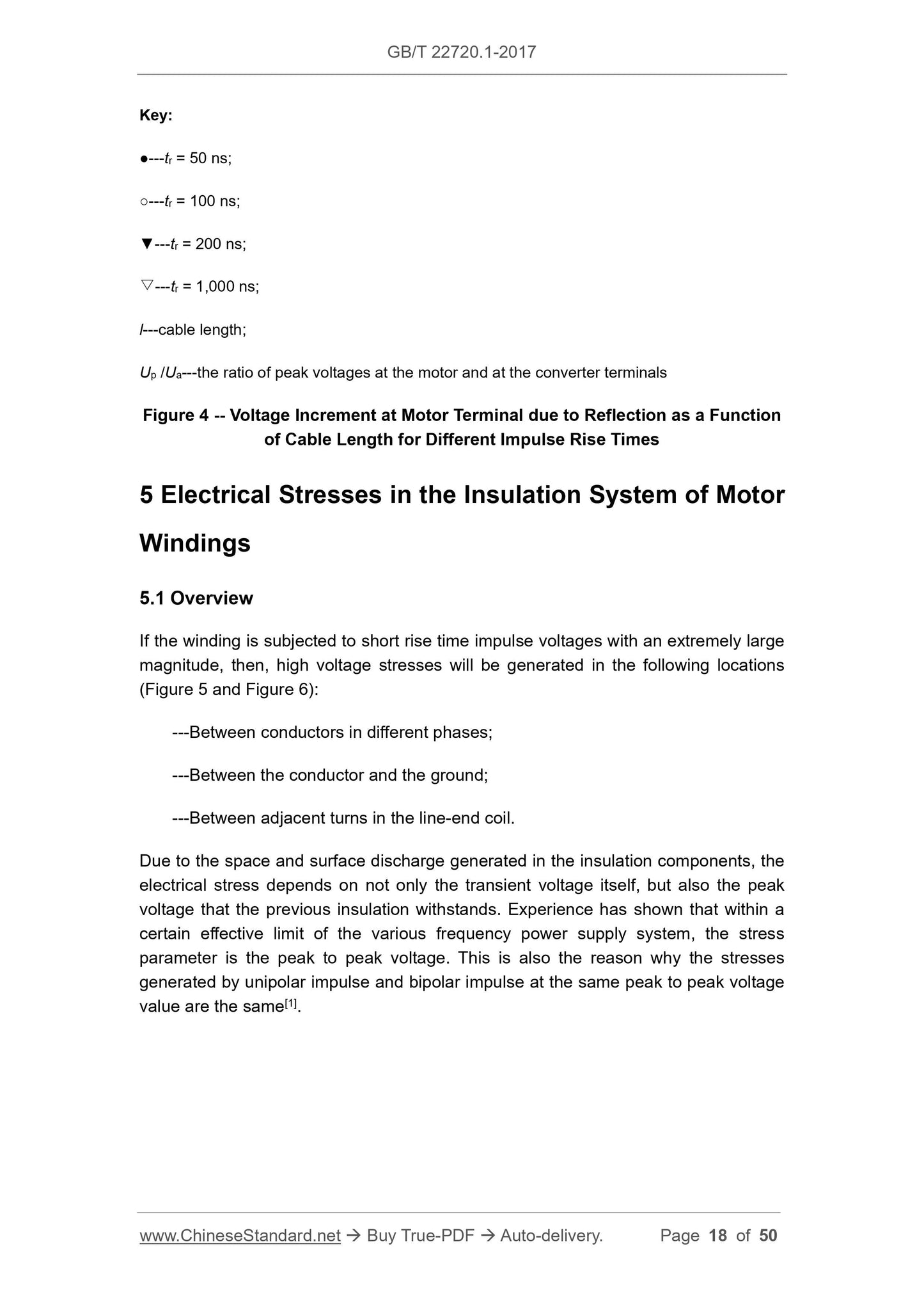
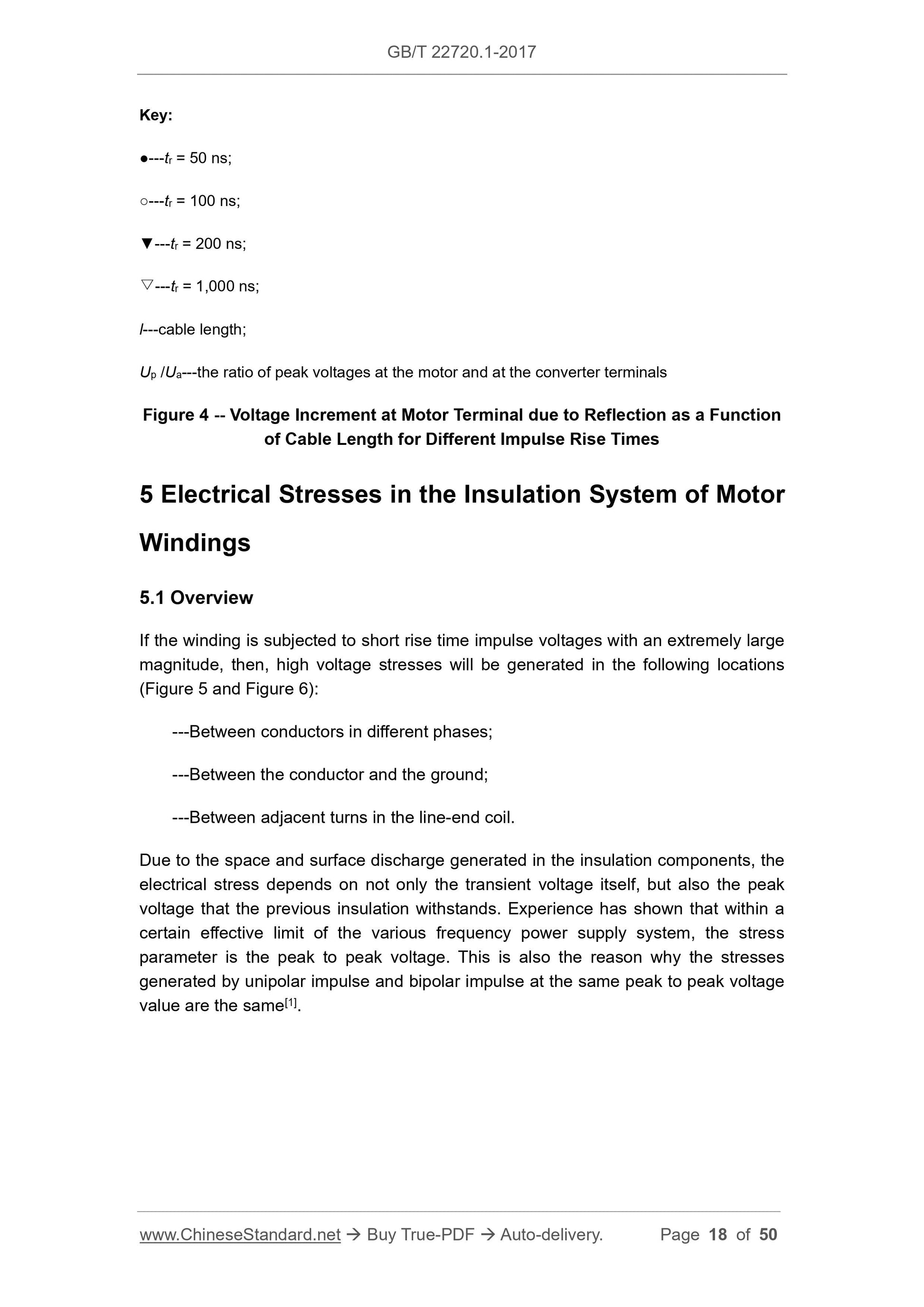
Key:
●---tr = 50 ns;
○---tr = 100 ns;
▼---tr = 200 ns;
▽---tr = 1,000 ns;
l---cable length;
Up /Ua---the ratio of peak voltages at the motor and at the converter terminals
Figure 4 -- Voltage Increment at Motor Terminal due to Reflection as a Function
of Cable Length for Different Impulse Rise Times
5 Electrical Stresses in the Insulation System of Motor
Windings
5.1 Overview
If the winding is subjected to short rise time impulse voltages with an extremely large
magnitude, then, high voltage stresses will be generated in the following locations
(Figure 5 and Figure 6):
---Between conductors in different phases;
---Between the conductor and the ground;
---Between adjacent turns in the line-end coil.
Due to the space and surface discharge generated in the insulation components, the
electrical stress depends on not only the transient voltage itself, but also the peak
voltage that the previous insulation withstands. Experience has shown that within a
certain effective limit of the various frequency power supply system, the stress
parameter is the peak to peak voltage. This is also the reason why the stresses
generated by unipolar impulse and bipolar impulse at the same peak to peak voltage
value are the same[1].
Key:
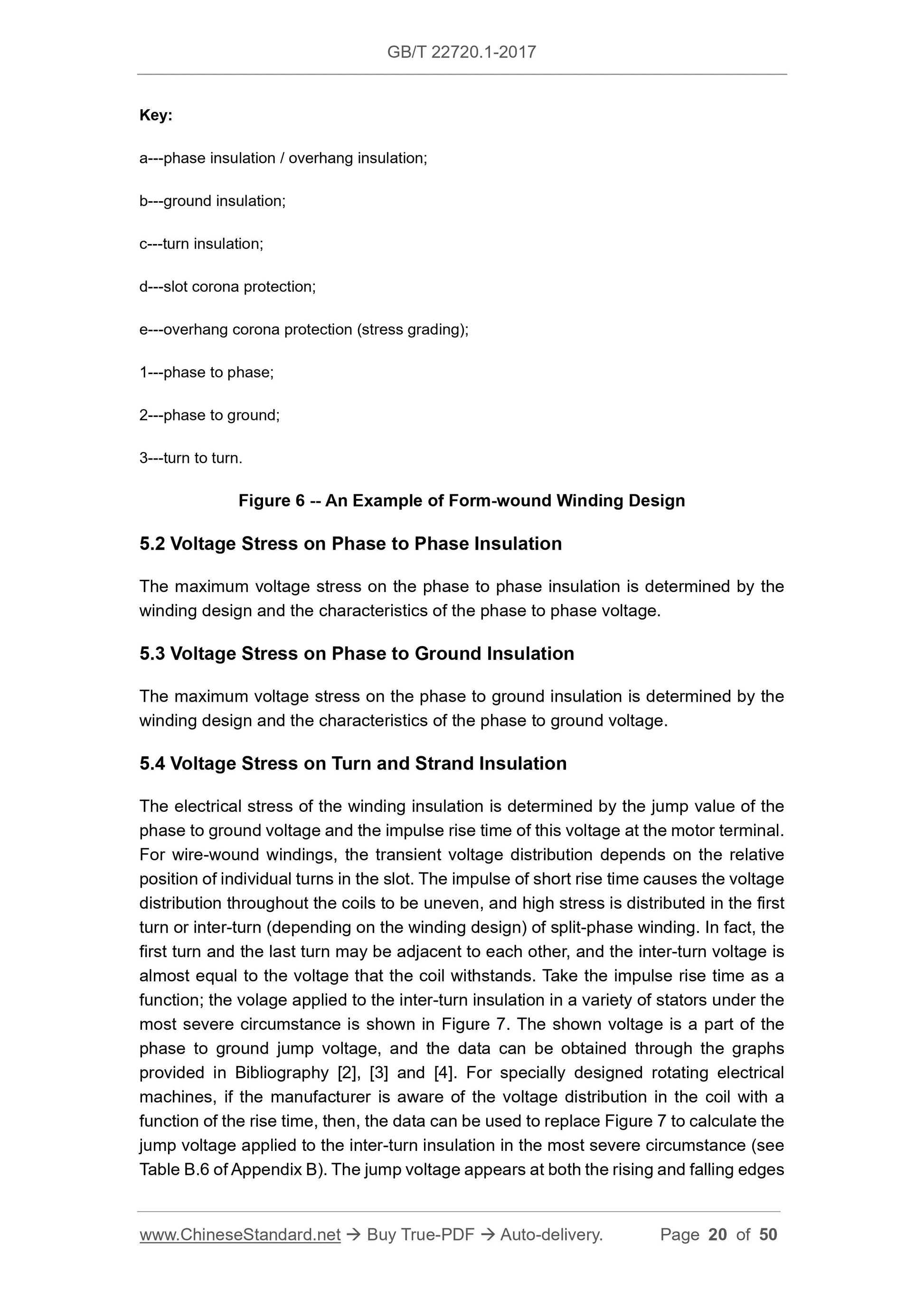
a---phase insulation / overhang insulation;
b---ground insulation;
c---turn insulation;
d---slot corona protection;
e---overhang corona protection (stress grading);
1---phase to phase;
2---phase to ground;
3---turn to turn.
Figure 6 -- An Example of Form-wound Winding Design
5.2 Voltage Stress on Phase to Phase Insulation
The maximum voltage stress on the phase to phase insulation is determined by the
winding design and the characteristics of the phase to phase voltage.
5.3 Voltage Stress on Phase to Ground Insulation
The maximum voltage stress on the phase to ground insulation is determined by the
winding design and the characteristics of the phase to ground voltage.
5.4 Voltage Stress on Turn and Strand Insulation
The electrical stress of the winding insulation is determined by the jump value of the
phase to ground voltage and the impulse rise time of this voltage at the motor terminal.
For wire-wound windings, the transient voltage distribution depends on the relative
position of individual turns in the slot. The impulse of short rise time causes the voltage
distribution throughout the coils to be uneven, and high stress is distributed in the first
turn or inter-turn (depending on the winding design) of split-phase winding. In fact, the
first turn and the last turn may be adjacent to each other, and the inter-turn voltage is
almost equal to the voltage that the coil withstands. Take the impulse rise time as a
function; the volage applied to the inter-turn insulation in a variety of stators under the
most severe circumstance is shown in Figure 7. The shown voltage is a part of the
phase to ground jump voltage, and the data can be obtained through the graphs
provided in Bibliography [2], [3] and [4]. For specially designed rotating electrical
machines, if the manufacturer is aware of the voltage distribution in the coil with a
function of the rise time, then, the data can be used to replace Figure 7 to calculate the
jump voltage applied to the inter-turn insulation in the most severe circumstance (see
Table B.6 of Appendix B). The jump voltage appears at both the rising and falling edges
resistant composite insulating materials, the designer can allow the existence of partial
discharges.
Another factor that may affect the insulation life is the high-frequency dielectric heating
caused by the converter waveform. If the coils have slot corona protection and stress
grading, then, the high-frequency current caused by the power supply in these
materials may cause overheating and degradation. The repetition frequency and the
frequencies related to the rise time of the rising edge will cause the insulating materials
to overheat due to dielectric loss. The most severe areas are the main wall insulation,
the inter-turn insulation and phase to phase insulation.
6 Types of Motor Insulation
This Part and IEC/TS 60034-18-42 divide winding insulations into two types. Type I
winding insulation (Figure 5) is not expected to withstand PD at any part of the
insulation during its life. Type II winding insulation (Figure 6) may have to withstand PD
in certain parts of the insulation during its life, so PD-resistant materials shall be used.
Motors with a rated voltage of 700 V and below may have both Type I and Type II
winding insulations. Motors with a rated voltage of above 700 V usually have Type II
winding insulation. The manufacturer specifies a rated voltage for each motor at a
power frequency, which assumes that the voltage from the power supply is 50 Hz or
60 Hz sinusoidal voltage. When the motor is fed from a converter, although the
manufacturer indicates a rated voltage of 50 Hz / 60 Hz and marks it on the nameplate
of the motor, the conventional definition of rated voltage is no longer applicable to the
winding insulation system. In order to solve this problem, the definition of impulse
voltage insulation class is introduced, which is to be separately indicated on the
instruction manual and nameplate as described in Appendix C. The classification of
Type I insulation can be determined by the absence of partial discharges during
operation or when subjected to the test procedures described in this Part.
7 Stress Categories for Type I Insulation Systems Used
in Motors Fed from Converters
In order to obtain sufficient reliability of the electric drive system, the strength of the
motor winding insulation system shall be coordinated with the electrical stress that it
bears. In other words,
---If the system supplier provides a complete electric drive system, it is responsible
for coordinating the strength of the motor winding insulation system and the
electrical stress, and ensuring the compatibility of the components, or;
---The drive system integrator shall explain to the motor designer the voltages that
appear at the motor terminal, so as to ensure that its design satisfies the
motorette or form-wound formette to conduct thermal cycling and treatment procedure
tests. The treatment procedure tests include mechanical vibration, moisture exposure
and high voltage test. The sample or the complete winding is used for diagnostic test,
the purpose of which is the evaluate the existence of PD. The second stage is the type
test of the complete winding or motor.
Based on the results of the qualification test and type test, determine the impulse
voltage insulation class of the motor, which specifies the maximum allowable voltage
applied to the insulation system under the power supply by the converter, expressed
in UN (see Appendix C).
8.2 Qualification Test
For this Part, the qualification test is used to study the capability of the insulation
systems to withstand various stresses. The qualification test of Type I insulation
systems is based on the voltage stress obtained through the thermal cycle and PDIV
test before and after other tests specified in IEC 60034-18-21 and IEC 60034-18-31,
and one of the stress categories specified in Chapter 7, multiplied by the increase
factor described in B.3. In accordance with IEC 60034-18-21...
Delivery: 9 seconds. Download (& Email) true-PDF + Invoice.
Get Quotation: Click GB/T 22720.1-2017 (Self-service in 1-minute)
Historical versions (Master-website): GB/T 22720.1-2017
Preview True-PDF (Reload/Scroll-down if blank)
GB/T 22720.1-2017
GB
NATIONAL STANDARD OF THE
PEOPLE’S REPUBLIC OF CHINA
ICS 29.160.01
K 20
GB/T 22720.1-2017 / IEC 60034-18-41:2014
Replacing GB/T 22720.1-2008
Rotating Electrical Machines - Qualification and
Quality Control Tests of Partial Discharge Free
Electrical Insulation Systems (Type I) Used in Rotating
Electrical Machines Fed from Voltage Converters
[IEC 60034-18-41:2014, Rotating Electrical Machines - Part 18-41:
Partial Discharge Free Electrical Insulation Systems (Type I) Used in
Rotating Electrical Machines Fed from Voltage Converters -
Qualification and Quality Control Tests, IDT]
ISSUED ON: NOVEMBER 1, 2017
IMPLEMENTED ON: MAY 1, 2018
Issued by: General Administration of Quality Supervision, Inspection and
Quarantine;
Standardization Administration of the People’s Republic of
China.
Table of Contents
Foreword ... 3
Introduction ... 6
1 Scope ... 8
2 Normative References ... 8
3 Terms and Definitions ... 9
4 Motor Terminal Voltage Generated during Converter Operation ... 14
5 Electrical Stresses in the Insulation System of Motor Windings ... 18
6 Types of Motor Insulation ... 22
7 Stress Categories for Type I Insulation Systems Used in Motors Fed from
Converters ... 22
8 Qualification and Type Tests of Type I Insulation Systems ... 24
9 Test Equipment ... 25
10 Qualification of Type I Insulation Systems ... 27
11 Type Test Procedures of Type I Insulation Systems ... 32
12 Exit-factory Inspection ... 34
13 Analysis, Report and Classification ... 34
Appendix A (informative) Terminal Voltages of a Converter-fed Motor during
Operation ... 35
Appendix B (normative) Test Voltages of Type I Insulation Systems ... 38
Appendix C (normative) Derivation of Allowable Voltages in Operation ... 47
Appendix NA (informative) Derivation and Example of Conventional Withstand
Voltage Test of Motors with a Rated Voltage of 500 V ... 49
Bibliography ... 50
Rotating Electrical Machines - Qualification and
Quality Control Tests of Partial Discharge Free
Electrical Insulation Systems (Type I) Used in Rotating
Electrical Machines Fed from Voltage Converters
1 Scope
This Part specifies the assessment criteria for stator / rotor winding insulation systems
fed from voltage-source pulse-width-modulation (PWM). This Part is applicable to the
stator / rotor winding insulation systems of single-phase or multi-phase AC motors
powdered by converters.
This Part specifies the qualification and quality control (type and exit-factory) tests for
typical samples or complete motors, so as to verify the degree of fitness with voltage-
source converters.
This Part is inapplicable to:
---Rotating electrical machines only started by converters;
---Rotating electrical machines whose rated voltage has an effective value of ≤
300 V;
---Rotor windings of rotating electrical machines with an operating voltage (peak
value) ≤ 200 V.
2 Normative References
The following documents are indispensable to the application of this document. In
terms of references with a specified date, only versions with a specified date are
applicable to this document. In terms of references without a specified date, the latest
version (including all the modifications) is applicable to this document.
GB/T 17948.7-2016 Rotating Electrical Machines - Functional Evaluation of Insulation
Systems - General Guidelines (IEC 60034-18-1:2010, IDT)
IEC 60034-18-21 Rotating Electrical Machines - Part 18-21: Functional Evaluation of
Insulation Systems - Test Procedures for Wire-wound Windings - Thermal Evaluation
and Classification
IEC 60034-18-31 Rotating Electrical Machines - Part 18-31: Functional Evaluation of
voltage, PDIV is defined as peak to peak voltage.
3.3 Partial Discharge Extinction Voltage
PDEV
Partial discharge extinction voltage refers to the voltage when the voltage applied to
the sample gradually decreases from a certain relatively high value where partial
discharge is detected to the voltage where no partial discharge can be detected in the
test circuit.
NOTE: for sinusoidal voltage, PDEV is defined as the effective value of voltage; for impulse
voltage, PDEV is defined as peak to peak voltage.
3.4 Peak (impulse) Voltage
Up
Peak (impulse) voltage refers to the highest voltage value that a unipolar impulse can
reach (for example, Up in Figure 1).
NOTE 1: for bipolar impulse voltage, the peak (impulse) voltage is half of the peak to peak
voltage (see Figure 2);
NOTE 2: the definition of peak to peak voltage is described in Chapter 4.
3.5 Steady State Voltage Impulse Magnitude
Ua
Steady state voltage impulse magnitude refers to the final magnitude of the impulse
voltage (see Figure 1).
3.6 Voltage Overshoot
Ub
Voltage overshoot refers to the magnitude of the peak voltage value exceeding the
steady state voltage impulse magnitude (see Figure 1).
3.7 Peak to Peak Impulse Voltage
Upk/pk
Peak to peak impulse voltage refers to the peak to peak voltage at the impulse
repetition rate (see Figure 2).
3.8 Peak to Peak Voltage
3.15 Formette
Formette refers to a special test model used for the evaluation of the electrical
insulation systems for form-wound windings.
3.16 Motorette
Motorette refers to a special test model used for the evaluation of the electrical
insulation systems for wire-wound windings.
3.17 (electric) Stress
(electric) stress refers to electric field strength, which is expressed in V/mm.
3.18 Rated Voltage
UN
Rated voltage refers to the voltage value of the motor under the conditions of power
frequency operation. It is specified by the manufacturer and marked on the nameplate.
3.19 Impulse Voltage Insulation Class
IVIC
Impulse voltage insulation class refers to the safe peak to peak voltage specified by
the manufacturer and related to the rated voltage for the motor fed from a specific
converter. It is marked in the instruction manual and on the nameplate.
3.20 Fundamental Frequency
Fundamental frequency refers to the frequency in the spectrum obtained through the
Fourier transform of the periodic time function. All frequencies in the spectrum are
related to it.
NOTE: for this Part, the fundamental frequency of the motor terminal voltage determines
the speed of the variable frequency motor.
3.21 Impulse Duration / Width
Impulse duration / width refers to the time interval between the first instant and the last
instant when the transient impulse value reaches the specified value of the impulse
magnitude or the specified threshold.
3.22 Jump Voltage
Uj
Jump voltage refers to the change of the voltage at the motor terminal at the beginning
Key:
●---tr = 50 ns;
○---tr = 100 ns;
▼---tr = 200 ns;
▽---tr = 1,000 ns;
l---cable length;
Up /Ua---the ratio of peak voltages at the motor and at the converter terminals
Figure 4 -- Voltage Increment at Motor Terminal due to Reflection as a Function
of Cable Length for Different Impulse Rise Times
5 Electrical Stresses in the Insulation System of Motor
Windings
5.1 Overview
If the winding is subjected to short rise time impulse voltages with an extremely large
magnitude, then, high voltage stresses will be generated in the following locations
(Figure 5 and Figure 6):
---Between conductors in different phases;
---Between the conductor and the ground;
---Between adjacent turns in the line-end coil.
Due to the space and surface discharge generated in the insulation components, the
electrical stress depends on not only the transient voltage itself, but also the peak
voltage that the previous insulation withstands. Experience has shown that within a
certain effective limit of the various frequency power supply system, the stress
parameter is the peak to peak voltage. This is also the reason why the stresses
generated by unipolar impulse and bipolar impulse at the same peak to peak voltage
value are the same[1].
Key:
a---phase insulation / overhang insulation;
b---ground insulation;
c---turn insulation;
d---slot corona protection;
e---overhang corona protection (stress grading);
1---phase to phase;
2---phase to ground;
3---turn to turn.
Figure 6 -- An Example of Form-wound Winding Design
5.2 Voltage Stress on Phase to Phase Insulation
The maximum voltage stress on the phase to phase insulation is determined by the
winding design and the characteristics of the phase to phase voltage.
5.3 Voltage Stress on Phase to Ground Insulation
The maximum voltage stress on the phase to ground insulation is determined by the
winding design and the characteristics of the phase to ground voltage.
5.4 Voltage Stress on Turn and Strand Insulation
The electrical stress of the winding insulation is determined by the jump value of the
phase to ground voltage and the impulse rise time of this voltage at the motor terminal.
For wire-wound windings, the transient voltage distribution depends on the relative
position of individual turns in the slot. The impulse of short rise time causes the voltage
distribution throughout the coils to be uneven, and high stress is distributed in the first
turn or inter-turn (depending on the winding design) of split-phase winding. In fact, the
first turn and the last turn may be adjacent to each other, and the inter-turn voltage is
almost equal to the voltage that the coil withstands. Take the impulse rise time as a
function; the volage applied to the inter-turn insulation in a variety of stators under the
most severe circumstance is shown in Figure 7. The shown voltage is a part of the
phase to ground jump voltage, and the data can be obtained through the graphs
provided in Bibliography [2], [3] and [4]. For specially designed rotating electrical
machines, if the manufacturer is aware of the voltage distribution in the coil with a
function of the rise time, then, the data can be used to replace Figure 7 to calculate the
jump voltage applied to the inter-turn insulation in the most severe circumstance (see
Table B.6 of Appendix B). The jump voltage appears at both the rising and falling edges
resistant composite insulating materials, the designer can allow the existence of partial
discharges.
Another factor that may affect the insulation life is the high-frequency dielectric heating
caused by the converter waveform. If the coils have slot corona protection and stress
grading, then, the high-frequency current caused by the power supply in these
materials may cause overheating and degradation. The repetition frequency and the
frequencies related to the rise time of the rising edge will cause the insulating materials
to overheat due to dielectric loss. The most severe areas are the main wall insulation,
the inter-turn insulation and phase to phase insulation.
6 Types of Motor Insulation
This Part and IEC/TS 60034-18-42 divide winding insulations into two types. Type I
winding insulation (Figure 5) is not expected to withstand PD at any part of the
insulation during its life. Type II winding insulation (Figure 6) may have to withstand PD
in certain parts of the insulation during its life, so PD-resistant materials shall be used.
Motors with a rated voltage of 700 V and below may have both Type I and Type II
winding insulations. Motors with a rated voltage of above 700 V usually have Type II
winding insulation. The manufacturer specifies a rated voltage for each motor at a
power frequency, which assumes that the voltage from the power supply is 50 Hz or
60 Hz sinusoidal voltage. When the motor is fed from a converter, although the
manufacturer indicates a rated voltage of 50 Hz / 60 Hz and marks it on the nameplate
of the motor, the conventional definition of rated voltage is no longer applicable to the
winding insulation system. In order to solve this problem, the definition of impulse
voltage insulation class is introduced, which is to be separately indicated on the
instruction manual and nameplate as described in Appendix C. The classification of
Type I insulation can be determined by the absence of partial discharges during
operation or when subjected to the test procedures described in this Part.
7 Stress Categories for Type I Insulation Systems Used
in Motors Fed from Converters
In order to obtain sufficient reliability of the electric drive system, the strength of the
motor winding insulation system shall be coordinated with the electrical stress that it
bears. In other words,
---If the system supplier provides a complete electric drive system, it is responsible
for coordinating the strength of the motor winding insulation system and the
electrical stress, and ensuring the compatibility of the components, or;
---The drive system integrator shall explain to the motor designer the voltages that
appear at the motor terminal, so as to ensure that its design satisfies the
motorette or form-wound formette to conduct thermal cycling and treatment procedure
tests. The treatment procedure tests include mechanical vibration, moisture exposure
and high voltage test. The sample or the complete winding is used for diagnostic test,
the purpose of which is the evaluate the existence of PD. The second stage is the type
test of the complete winding or motor.
Based on the results of the qualification test and type test, determine the impulse
voltage insulation class of the motor, which specifies the maximum allowable voltage
applied to the insulation system under the power supply by the converter, expressed
in UN (see Appendix C).
8.2 Qualification Test
For this Part, the qualification test is used to study the capability of the insulation
systems to withstand various stresses. The qualification test of Type I insulation
systems is based on the voltage stress obtained through the thermal cycle and PDIV
test before and after other tests specified in IEC 60034-18-21 and IEC 60034-18-31,
and one of the stress categories specified in Chapter 7, multiplied by the increase
factor described in B.3. In accordance with IEC 60034-18-21...
Share