1
/
of
12
PayPal, credit cards. Download editable-PDF and invoice in 1 second!
GB/T 27930-2023 English PDF (GB/T27930-2023)
GB/T 27930-2023 English PDF (GB/T27930-2023)
Regular price
$1,805.00 USD
Regular price
Sale price
$1,805.00 USD
Unit price
/
per
Shipping calculated at checkout.
Couldn't load pickup availability
Delivery: 3 seconds. Download true-PDF + Invoice.
Get Quotation: Click GB/T 27930-2023 (Self-service in 1-minute)
Historical versions (Master-website): GB/T 27930-2023
Preview True-PDF (Reload/Scroll-down if blank)
GB/T 27930-2023: Digital communication protocols between off-board conductive charger and electric vehicle
GB/T 27930-2023
ChaoJi-1 (Chinese standard GB/T) and compatible CHAdeMO-3.1 (Japanese standard, joint-development with Chinese standard) are consisted of GB/T 18487.1-2023, GB/T27930-2023, and GB/T 20234.4-2023. It is suitable for high, medium and low power charging (up to 1.2MW) to meet the needs of safe and fast electric-vehicle charging.
GB
NATIONAL STANDARD OF THE
PEOPLE’S REPUBLIC OF CHINA
ICS 29.200
CCS K 81
Replacing GB/T 27930-2015
Digital communication protocols between off-board
conductive charger and electric vehicle
ISSUED ON: SEPTEMBER 07, 2023
IMPLEMENTED ON: APRIL 01, 2024
Issued by: Status Administration for Market Regulation.
Standardization Administration of PRC.
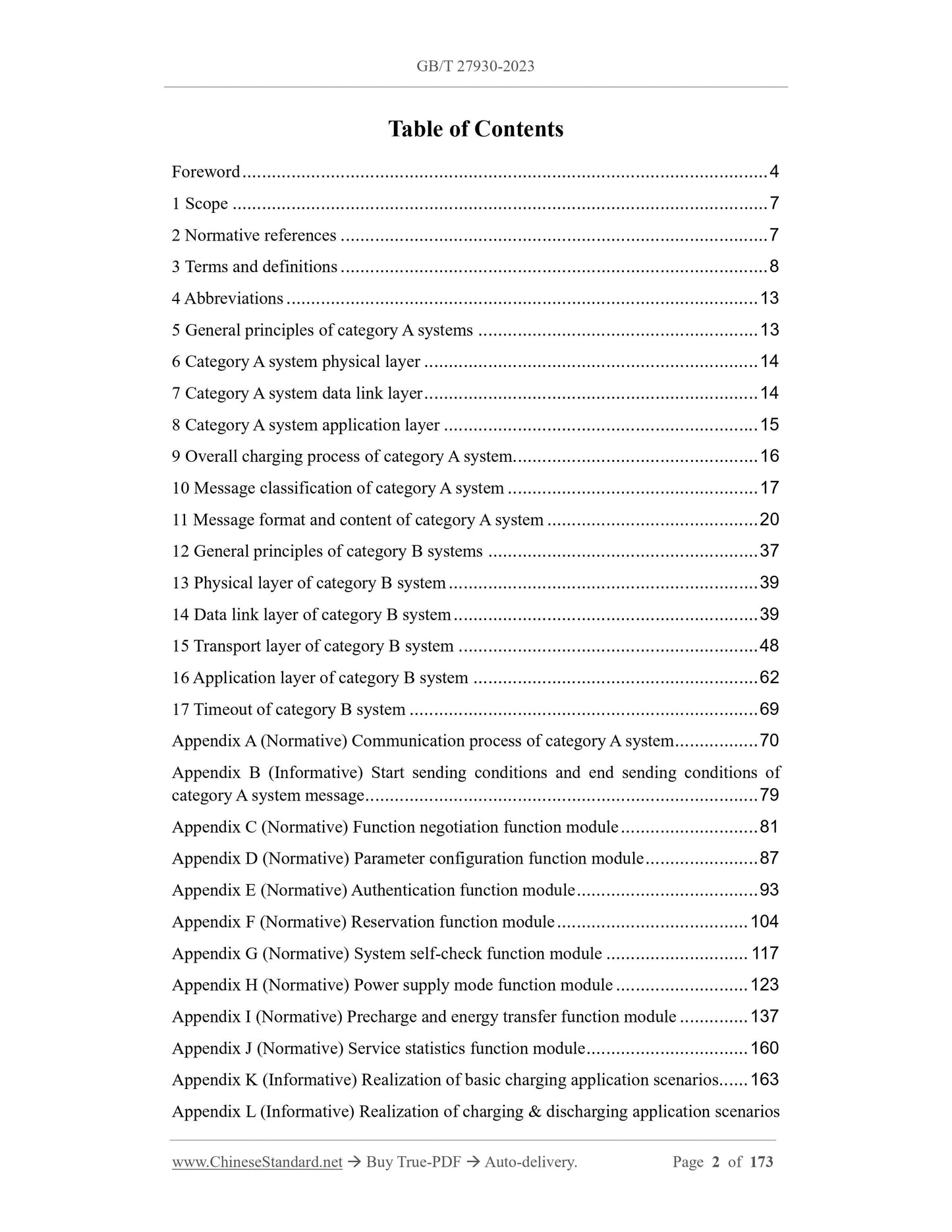
Table of Contents
Foreword ... 4
1 Scope ... 7
2 Normative references ... 7
3 Terms and definitions ... 8
4 Abbreviations ... 13
5 General principles of category A systems ... 13
6 Category A system physical layer ... 14
7 Category A system data link layer ... 14
8 Category A system application layer ... 15
9 Overall charging process of category A system... 16
10 Message classification of category A system ... 17
11 Message format and content of category A system ... 20
12 General principles of category B systems ... 37
13 Physical layer of category B system ... 39
14 Data link layer of category B system ... 39
15 Transport layer of category B system ... 48
16 Application layer of category B system ... 62
17 Timeout of category B system ... 69
Appendix A (Normative) Communication process of category A system ... 70
Appendix B (Informative) Start sending conditions and end sending conditions of
category A system message ... 79
Appendix C (Normative) Function negotiation function module ... 81
Appendix D (Normative) Parameter configuration function module ... 87
Appendix E (Normative) Authentication function module ... 93
Appendix F (Normative) Reservation function module ... 104
Appendix G (Normative) System self-check function module ... 117
Appendix H (Normative) Power supply mode function module ... 123
Appendix I (Normative) Precharge and energy transfer function module ... 137
Appendix J (Normative) Service statistics function module ... 160
Appendix K (Informative) Realization of basic charging application scenarios ... 163
Appendix L (Informative) Realization of charging and discharging application scenarios
... 165
Appendix M (Normative) Parameter type table ... 168
Appendix N (Informative) Realization of adaptor communication ... 173
Digital communication protocols between off-board
conductive charger and electric vehicle
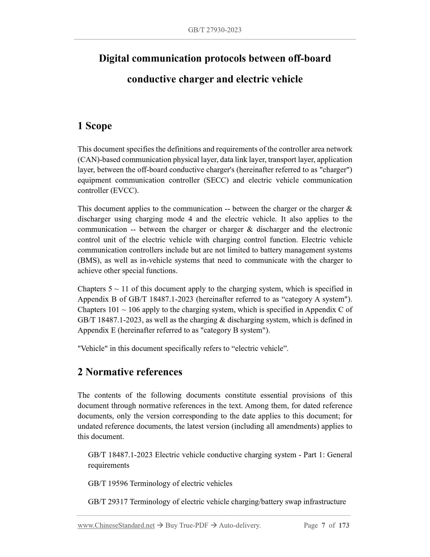
1 Scope
This document specifies the definitions and requirements of the controller area network
(CAN)-based communication physical layer, data link layer, transport layer, application
layer, between the off-board conductive charger's (hereinafter referred to as "charger")
equipment communication controller (SECC) and electric vehicle communication
controller (EVCC).
This document applies to the communication -- between the charger or the charger and
discharger using charging mode 4 and the electric vehicle. It also applies to the
communication -- between the charger or charger and discharger and the electronic
control unit of the electric vehicle with charging control function. Electric vehicle
communication controllers include but are not limited to battery management systems
(BMS), as well as in-vehicle systems that need to communicate with the charger to
achieve other special functions.
Chapters 5 ~ 11 of this document apply to the charging system, which is specified in
Appendix B of GB/T 18487.1-2023 (hereinafter referred to as “category A system").
Chapters 101 ~ 106 apply to the charging system, which is specified in Appendix C of
GB/T 18487.1-2023, as well as the charging and discharging system, which is defined in
Appendix E (hereinafter referred to as "category B system").
"Vehicle" in this document specifically refers to “electric vehicle”.
2 Normative references
The contents of the following documents constitute essential provisions of this
document through normative references in the text. Among them, for dated reference
documents, only the version corresponding to the date applies to this document; for
undated reference documents, the latest version (including all amendments) applies to
this document.
GB/T 18487.1-2023 Electric vehicle conductive charging system - Part 1: General
requirements
GB/T 19596 Terminology of electric vehicles
GB/T 29317 Terminology of electric vehicle charging/battery swap infrastructure
Extended vehicle identification number; EVIN
Vehicle identification number (VIN code), or a vehicle identifier with the words I,
O, Q designed, to identify vehicle identity information.
Note: Standards related to extended vehicle identification numbers are under consideration.
4 Abbreviations
The following abbreviations apply to this document.
LM_ACK: Long message acknowledgement
LM_EndofACK: Long message end of acknowledge
LM_NACK: Long message negative acknowledge
RM_SM_ACK: Reliable short message acknowledge
5 General principles of category A systems
5.1 The communication network between the charger and the vehicle is based on
CAN2.0B.
5.2 The CAN communication network, between the charger and the vehicle, shall be
composed of two nodes: the charger and the vehicle. In order to achieve the
compatibility solution of Appendix G of GB/T 18487.1-2023, adaptor nodes can be
added to the communication network; however, between each node, there shall be no
conflicts in addresses, PGNs, etc.
5.3 Data information transmission adopts the format of low byte sent first.
5.4 The current value during vehicle charging is negative. In public stations, when the
vehicle/charger receives a charging current value, which is outside the range of -400 A
~ 0 A, the charging process shall be exited. In private stations, the charger and vehicle
can be subject to the negotiation, according to private agreement.
5.5 In public stations, messages not specified in this document shall not appear on the
communication network, between chargers and vehicles. Messages, which are not
specified in this document and received by the charger or vehicle, will not be processed.
5.6 The conversion relationship between the data value and the physical quantity in the
message is: physical quantity = Resolution × Data value + Offset.
5.7 Chargers and vehicles, that implement this document, shall have forward
compatibility.
data packet, based on PGN.
8.3 Use periodic sending and event-driven methods to send data.
8.4 If multiple PGN data need to be sent to implement a function, all the defined
multiple PGN messages must be received, to determine whether the function is
successfully sent.
8.5 When defining a new parameter group, try to put parameters with the same function,
parameters with the same or similar transmission cycle, parameters belonging to the
same subsystem in the same parameter group. At the same time, the new parameter
group must make full use of the data width in 8 bytes; try to put related parameters in
the same group; consider extendibility; reserve some bytes or bits for future
modifications.
8.6 When modifying the parameter group defined in Chapter 10, the newly added
parameters must be related to the original parameters in the parameter group. Irrelevant
parameters shall not be added to the defined PGN in order to save the number of PGN.
8.7 Parameter options are divided into mandatory items and optional items. The
mandatory item parameters shall send actual data, according to the format specified in
this document. Optional item parameters can send actual data, according to the format
specified in this document, OR all bits shall be filled with 1 and sent. For all contents
in the same message which are optional. the sender does not need to send the message.
If it is sent, the actual data shall be sent in the format specified in this document. The
optional item parameters that do not send the actual data are filled with 1.
8.8 The message shall be sent according to the length specified in this document; the
undefined bits in the specified length shall be filled with 1.
8.9 "Untrusted status" is content sent in order to maintain the communication link, when
the sender cannot obtain or clarify the current status. The receiver shall ignore and not
process the information.
9 Overall charging process of category A system
The entire charging process includes six phases: physical connection completion, low-
voltage auxiliary power-on, charging handshake phase, charging parameter
configuration phase, charging phase, charging end phase, as shown in Figure 1. After
the physical connection and the low-voltage auxiliary power-on is completed, the two
parties start communication. At each phase of communication, if the charger and the
vehicle do not receive each other's message OR do not receive the correct message
within the specified time, it is determined to be timeout (timeout means that the other
party's complete data packet or correct data packet is not received within the specified
time), the communication process shall comply with the requirements of Appendix A.
< 00>: = The charger temperature is normal; < 01>: = The charger is overtemperature;
< 10>: = Untrusted status;
Bits 3 ~ 4: Charging connector failure
< 00>: = Charging connector is normal; < 01>: = Charging connector fault; < 10>: =
Untrusted status;
Bits 5 ~ 6: Charger internal over-temperature fault
< 00>: = The internal temperature of the charger is normal; < 01>: = The internal of
the charger is overtemperature; < 10>: = Untrusted status;
Bits 7 ~ 8: The required power cannot be transferred
< 00>: = Power transmission is normal; < 01>: Power cannot be transmitted; < 10>:
= Untrusted status;
Bits 9 ~ 10: Charger emergency stop failure
< 00>: = Normal; < 01>: = Charger emergency stop; < 10>: = Untrusted status;
Bits 11 ~ 12: Other faults
< 00>: = Normal; < 01>: = Fault; < 10>: = Untrusted status.
Bits 13 ~ 14: Self-check faults (including faults that occur during self-check, such
as insulation detection, short circuit test, adhesion detection, etc.)
< 00>: = Normal; < 01>: = Fault; < 10>: = Untrusted status.
Bits 15 ~ 16: Pre-charge fault (including pre-charge voltage mismatch, pre-charge
fault, etc.)
< 00>: = Normal; < 01>: = Fault; < 10>: = Untrusted status.
3) Reasons for SPN3523 charger suspension charging error
Bits 1 ~ 2: Current mismatch
< 00>: = Current matching; < 01>: = Current mismatch; < 10>: = Untrusted status;
Bits 3 ~ 4: Abnormal voltage
< 00>: = Normal; < 01>: = Abnormal voltage; < 10>: = Untrusted status.
Bits 5 ~ 6: Charging parameters mismatch
< 00>: = Parameter match; < 01>: = Parameter mismatch; < 10>: = Untrusted status.
LMS_T1 between information frames shall be between 1 ms ~ 10 ms.
15.4.1.7 The "starting frame number to receive" as received by the sender and the
"frame sequence number" as received by the receiver shall be less than or equal to the
maximum frame sequence number. Otherwise, the sender or receiver sends LM_NACK
and returns "sending failure" information to the application layer. The application layer
determines the processing method.
15.4.1.8 Both the sender and the receiver can send LM_NACK, to actively terminate
the transmission. After receiving LM_NACK, both parties exit the transmission of long
messages; the connection is closed; the receiver does not process the received message.
15.4.1.9 When three consecutive connection timeouts of the same type occur, the sender
and/or receiver shall send LM_NACK to close the connection; return a "sending
failure" message to the application layer, which will decide whether to resend.
15.4.1.10 Since the information frames of different long messages, which have the same
frame sequence number, cannot be distinguished, only one connection is allowed to be
established at the same time, that is, a new connection can be established, only when
the sender or receiver sends LM_NACK or the receiver sends LM_EndofACK.
15.4.2 Packet reorganization
15.4.2.1 The data length of a long message is greater than 8 bytes; it needs to be split
into multiple information frames when sending: In order to ensure that the information
frame can be identified and reorganized, the first byte of the information frame data
field is defined as the frame serial number of the information frame, the serial number
range is 1 ~ 255. The remaining 7 bytes in the data field are used to load the content,
which is defined by the application layer message structure (if the data field of the last
frame is less than 8 bytes, it is filled with 0xFF).
15.4.2.2 After receiving all information frames, the receiver shall reorganize them back
to the original information, according to the frame sequence number from small to large
(starting from 1).
15.4.3 Connection management
15.4.3.1 Overview
The connection in the multi-information frame transmission mode is a temporary link,
which is established between two nodes, for the purpose of transmitting long messages.
The connection management specifies the establishment of the connection (see
15.4.3.2), data transmission (see 15.4.3.3), the closing of the connection (see 15.4.3.3).
See 15.4.3.4). The long message transmission, which is specified in this document, is
point-to-point; its connection management includes:
- Before the connection is established, both the sender and the receiver shall confirm
that the counter recording the frame sequence number is 0, where the sender
counter is used to record the frame sequence number to be sent next; the receiver
counter is used to record the starting frame sequence number to be received next
time;
- The sender sends an information frame, which has a frame number 0, to request to
establish a connection. After the receiver responds and confirms, the connection is
successfully established;
- After the connection is established, the sender sends the information frame
accordin...
Get Quotation: Click GB/T 27930-2023 (Self-service in 1-minute)
Historical versions (Master-website): GB/T 27930-2023
Preview True-PDF (Reload/Scroll-down if blank)
GB/T 27930-2023: Digital communication protocols between off-board conductive charger and electric vehicle
GB/T 27930-2023
ChaoJi-1 (Chinese standard GB/T) and compatible CHAdeMO-3.1 (Japanese standard, joint-development with Chinese standard) are consisted of GB/T 18487.1-2023, GB/T27930-2023, and GB/T 20234.4-2023. It is suitable for high, medium and low power charging (up to 1.2MW) to meet the needs of safe and fast electric-vehicle charging.
GB
NATIONAL STANDARD OF THE
PEOPLE’S REPUBLIC OF CHINA
ICS 29.200
CCS K 81
Replacing GB/T 27930-2015
Digital communication protocols between off-board
conductive charger and electric vehicle
ISSUED ON: SEPTEMBER 07, 2023
IMPLEMENTED ON: APRIL 01, 2024
Issued by: Status Administration for Market Regulation.
Standardization Administration of PRC.
Table of Contents
Foreword ... 4
1 Scope ... 7
2 Normative references ... 7
3 Terms and definitions ... 8
4 Abbreviations ... 13
5 General principles of category A systems ... 13
6 Category A system physical layer ... 14
7 Category A system data link layer ... 14
8 Category A system application layer ... 15
9 Overall charging process of category A system... 16
10 Message classification of category A system ... 17
11 Message format and content of category A system ... 20
12 General principles of category B systems ... 37
13 Physical layer of category B system ... 39
14 Data link layer of category B system ... 39
15 Transport layer of category B system ... 48
16 Application layer of category B system ... 62
17 Timeout of category B system ... 69
Appendix A (Normative) Communication process of category A system ... 70
Appendix B (Informative) Start sending conditions and end sending conditions of
category A system message ... 79
Appendix C (Normative) Function negotiation function module ... 81
Appendix D (Normative) Parameter configuration function module ... 87
Appendix E (Normative) Authentication function module ... 93
Appendix F (Normative) Reservation function module ... 104
Appendix G (Normative) System self-check function module ... 117
Appendix H (Normative) Power supply mode function module ... 123
Appendix I (Normative) Precharge and energy transfer function module ... 137
Appendix J (Normative) Service statistics function module ... 160
Appendix K (Informative) Realization of basic charging application scenarios ... 163
Appendix L (Informative) Realization of charging and discharging application scenarios
... 165
Appendix M (Normative) Parameter type table ... 168
Appendix N (Informative) Realization of adaptor communication ... 173
Digital communication protocols between off-board
conductive charger and electric vehicle
1 Scope
This document specifies the definitions and requirements of the controller area network
(CAN)-based communication physical layer, data link layer, transport layer, application
layer, between the off-board conductive charger's (hereinafter referred to as "charger")
equipment communication controller (SECC) and electric vehicle communication
controller (EVCC).
This document applies to the communication -- between the charger or the charger and
discharger using charging mode 4 and the electric vehicle. It also applies to the
communication -- between the charger or charger and discharger and the electronic
control unit of the electric vehicle with charging control function. Electric vehicle
communication controllers include but are not limited to battery management systems
(BMS), as well as in-vehicle systems that need to communicate with the charger to
achieve other special functions.
Chapters 5 ~ 11 of this document apply to the charging system, which is specified in
Appendix B of GB/T 18487.1-2023 (hereinafter referred to as “category A system").
Chapters 101 ~ 106 apply to the charging system, which is specified in Appendix C of
GB/T 18487.1-2023, as well as the charging and discharging system, which is defined in
Appendix E (hereinafter referred to as "category B system").
"Vehicle" in this document specifically refers to “electric vehicle”.
2 Normative references
The contents of the following documents constitute essential provisions of this
document through normative references in the text. Among them, for dated reference
documents, only the version corresponding to the date applies to this document; for
undated reference documents, the latest version (including all amendments) applies to
this document.
GB/T 18487.1-2023 Electric vehicle conductive charging system - Part 1: General
requirements
GB/T 19596 Terminology of electric vehicles
GB/T 29317 Terminology of electric vehicle charging/battery swap infrastructure
Extended vehicle identification number; EVIN
Vehicle identification number (VIN code), or a vehicle identifier with the words I,
O, Q designed, to identify vehicle identity information.
Note: Standards related to extended vehicle identification numbers are under consideration.
4 Abbreviations
The following abbreviations apply to this document.
LM_ACK: Long message acknowledgement
LM_EndofACK: Long message end of acknowledge
LM_NACK: Long message negative acknowledge
RM_SM_ACK: Reliable short message acknowledge
5 General principles of category A systems
5.1 The communication network between the charger and the vehicle is based on
CAN2.0B.
5.2 The CAN communication network, between the charger and the vehicle, shall be
composed of two nodes: the charger and the vehicle. In order to achieve the
compatibility solution of Appendix G of GB/T 18487.1-2023, adaptor nodes can be
added to the communication network; however, between each node, there shall be no
conflicts in addresses, PGNs, etc.
5.3 Data information transmission adopts the format of low byte sent first.
5.4 The current value during vehicle charging is negative. In public stations, when the
vehicle/charger receives a charging current value, which is outside the range of -400 A
~ 0 A, the charging process shall be exited. In private stations, the charger and vehicle
can be subject to the negotiation, according to private agreement.
5.5 In public stations, messages not specified in this document shall not appear on the
communication network, between chargers and vehicles. Messages, which are not
specified in this document and received by the charger or vehicle, will not be processed.
5.6 The conversion relationship between the data value and the physical quantity in the
message is: physical quantity = Resolution × Data value + Offset.
5.7 Chargers and vehicles, that implement this document, shall have forward
compatibility.
data packet, based on PGN.
8.3 Use periodic sending and event-driven methods to send data.
8.4 If multiple PGN data need to be sent to implement a function, all the defined
multiple PGN messages must be received, to determine whether the function is
successfully sent.
8.5 When defining a new parameter group, try to put parameters with the same function,
parameters with the same or similar transmission cycle, parameters belonging to the
same subsystem in the same parameter group. At the same time, the new parameter
group must make full use of the data width in 8 bytes; try to put related parameters in
the same group; consider extendibility; reserve some bytes or bits for future
modifications.
8.6 When modifying the parameter group defined in Chapter 10, the newly added
parameters must be related to the original parameters in the parameter group. Irrelevant
parameters shall not be added to the defined PGN in order to save the number of PGN.
8.7 Parameter options are divided into mandatory items and optional items. The
mandatory item parameters shall send actual data, according to the format specified in
this document. Optional item parameters can send actual data, according to the format
specified in this document, OR all bits shall be filled with 1 and sent. For all contents
in the same message which are optional. the sender does not need to send the message.
If it is sent, the actual data shall be sent in the format specified in this document. The
optional item parameters that do not send the actual data are filled with 1.
8.8 The message shall be sent according to the length specified in this document; the
undefined bits in the specified length shall be filled with 1.
8.9 "Untrusted status" is content sent in order to maintain the communication link, when
the sender cannot obtain or clarify the current status. The receiver shall ignore and not
process the information.
9 Overall charging process of category A system
The entire charging process includes six phases: physical connection completion, low-
voltage auxiliary power-on, charging handshake phase, charging parameter
configuration phase, charging phase, charging end phase, as shown in Figure 1. After
the physical connection and the low-voltage auxiliary power-on is completed, the two
parties start communication. At each phase of communication, if the charger and the
vehicle do not receive each other's message OR do not receive the correct message
within the specified time, it is determined to be timeout (timeout means that the other
party's complete data packet or correct data packet is not received within the specified
time), the communication process shall comply with the requirements of Appendix A.
< 00>: = The charger temperature is normal; < 01>: = The charger is overtemperature;
< 10>: = Untrusted status;
Bits 3 ~ 4: Charging connector failure
< 00>: = Charging connector is normal; < 01>: = Charging connector fault; < 10>: =
Untrusted status;
Bits 5 ~ 6: Charger internal over-temperature fault
< 00>: = The internal temperature of the charger is normal; < 01>: = The internal of
the charger is overtemperature; < 10>: = Untrusted status;
Bits 7 ~ 8: The required power cannot be transferred
< 00>: = Power transmission is normal; < 01>: Power cannot be transmitted; < 10>:
= Untrusted status;
Bits 9 ~ 10: Charger emergency stop failure
< 00>: = Normal; < 01>: = Charger emergency stop; < 10>: = Untrusted status;
Bits 11 ~ 12: Other faults
< 00>: = Normal; < 01>: = Fault; < 10>: = Untrusted status.
Bits 13 ~ 14: Self-check faults (including faults that occur during self-check, such
as insulation detection, short circuit test, adhesion detection, etc.)
< 00>: = Normal; < 01>: = Fault; < 10>: = Untrusted status.
Bits 15 ~ 16: Pre-charge fault (including pre-charge voltage mismatch, pre-charge
fault, etc.)
< 00>: = Normal; < 01>: = Fault; < 10>: = Untrusted status.
3) Reasons for SPN3523 charger suspension charging error
Bits 1 ~ 2: Current mismatch
< 00>: = Current matching; < 01>: = Current mismatch; < 10>: = Untrusted status;
Bits 3 ~ 4: Abnormal voltage
< 00>: = Normal; < 01>: = Abnormal voltage; < 10>: = Untrusted status.
Bits 5 ~ 6: Charging parameters mismatch
< 00>: = Parameter match; < 01>: = Parameter mismatch; < 10>: = Untrusted status.
LMS_T1 between information frames shall be between 1 ms ~ 10 ms.
15.4.1.7 The "starting frame number to receive" as received by the sender and the
"frame sequence number" as received by the receiver shall be less than or equal to the
maximum frame sequence number. Otherwise, the sender or receiver sends LM_NACK
and returns "sending failure" information to the application layer. The application layer
determines the processing method.
15.4.1.8 Both the sender and the receiver can send LM_NACK, to actively terminate
the transmission. After receiving LM_NACK, both parties exit the transmission of long
messages; the connection is closed; the receiver does not process the received message.
15.4.1.9 When three consecutive connection timeouts of the same type occur, the sender
and/or receiver shall send LM_NACK to close the connection; return a "sending
failure" message to the application layer, which will decide whether to resend.
15.4.1.10 Since the information frames of different long messages, which have the same
frame sequence number, cannot be distinguished, only one connection is allowed to be
established at the same time, that is, a new connection can be established, only when
the sender or receiver sends LM_NACK or the receiver sends LM_EndofACK.
15.4.2 Packet reorganization
15.4.2.1 The data length of a long message is greater than 8 bytes; it needs to be split
into multiple information frames when sending: In order to ensure that the information
frame can be identified and reorganized, the first byte of the information frame data
field is defined as the frame serial number of the information frame, the serial number
range is 1 ~ 255. The remaining 7 bytes in the data field are used to load the content,
which is defined by the application layer message structure (if the data field of the last
frame is less than 8 bytes, it is filled with 0xFF).
15.4.2.2 After receiving all information frames, the receiver shall reorganize them back
to the original information, according to the frame sequence number from small to large
(starting from 1).
15.4.3 Connection management
15.4.3.1 Overview
The connection in the multi-information frame transmission mode is a temporary link,
which is established between two nodes, for the purpose of transmitting long messages.
The connection management specifies the establishment of the connection (see
15.4.3.2), data transmission (see 15.4.3.3), the closing of the connection (see 15.4.3.3).
See 15.4.3.4). The long message transmission, which is specified in this document, is
point-to-point; its connection management includes:
- Before the connection is established, both the sender and the receiver shall confirm
that the counter recording the frame sequence number is 0, where the sender
counter is used to record the frame sequence number to be sent next; the receiver
counter is used to record the starting frame sequence number to be received next
time;
- The sender sends an information frame, which has a frame number 0, to request to
establish a connection. After the receiver responds and confirms, the connection is
successfully established;
- After the connection is established, the sender sends the information frame
accordin...
Share