1
/
of
7
PayPal, credit cards. Download editable-PDF and invoice in 1 second!
GB/T 33014.10-2020 English PDF (GBT33014.10-2020)
GB/T 33014.10-2020 English PDF (GBT33014.10-2020)
Regular price
$155.00 USD
Regular price
Sale price
$155.00 USD
Unit price
/
per
Shipping calculated at checkout.
Couldn't load pickup availability
Delivery: 3 seconds. Download true-PDF + Invoice.
Get QUOTATION in 1-minute: Click GB/T 33014.10-2020
Historical versions: GB/T 33014.10-2020
Preview True-PDF (Reload/Scroll if blank)
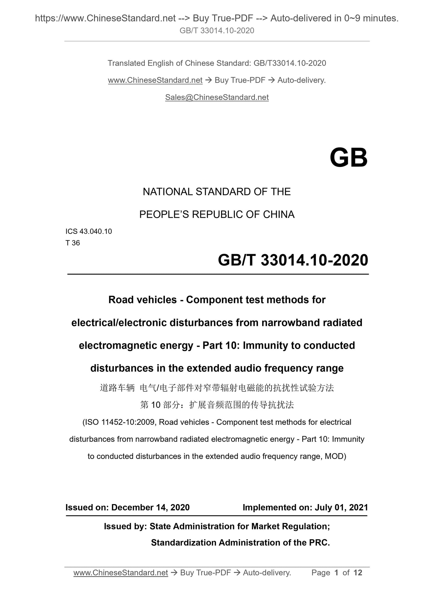
GB/T 33014.10-2020: Road vehicles. Component test methods for electrical/electronic disturbances from narrowband radiated electromagnetic energy -- Part 10: Immunity to conducted disturbances in the extended audio frequency range
GB/T 33014.10-2020
GB
NATIONAL STANDARD OF THE
PEOPLE’S REPUBLIC OF CHINA
ICS 43.040.10
T 36
Road vehicles - Component test methods for
electrical/electronic disturbances from narrowband radiated
electromagnetic energy - Part 10: Immunity to conducted
disturbances in the extended audio frequency range
(ISO 11452-10:2009, Road vehicles - Component test methods for electrical
disturbances from narrowband radiated electromagnetic energy - Part 10: Immunity
to conducted disturbances in the extended audio frequency range, MOD)
ISSUED ON: DECEMBER 14, 2020
IMPLEMENTED ON: JULY 01, 2021
Issued by: State Administration for Market Regulation;
Standardization Administration of the PRC.
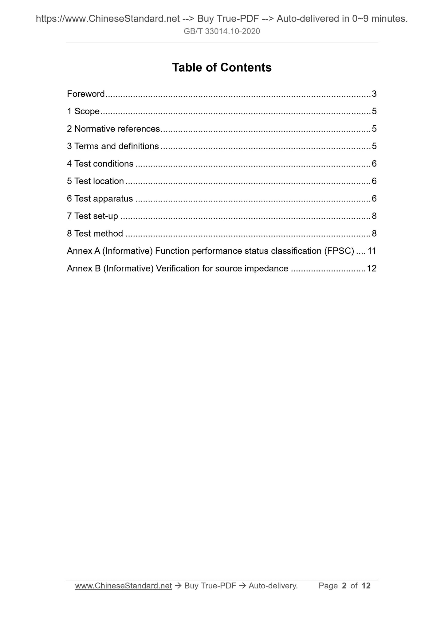
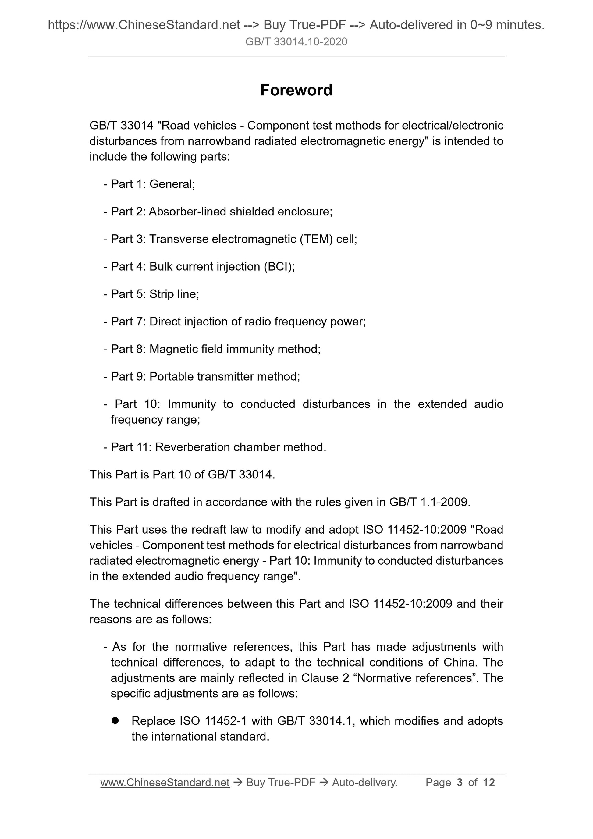
Table of Contents
Foreword ... 3
1 Scope ... 5
2 Normative references ... 5
3 Terms and definitions ... 5
4 Test conditions ... 6
5 Test location ... 6
6 Test apparatus ... 6
7 Test set-up ... 8
8 Test method ... 8
Annex A (Informative) Function performance status classification (FPSC) ... 11
Annex B (Informative) Verification for source impedance ... 12
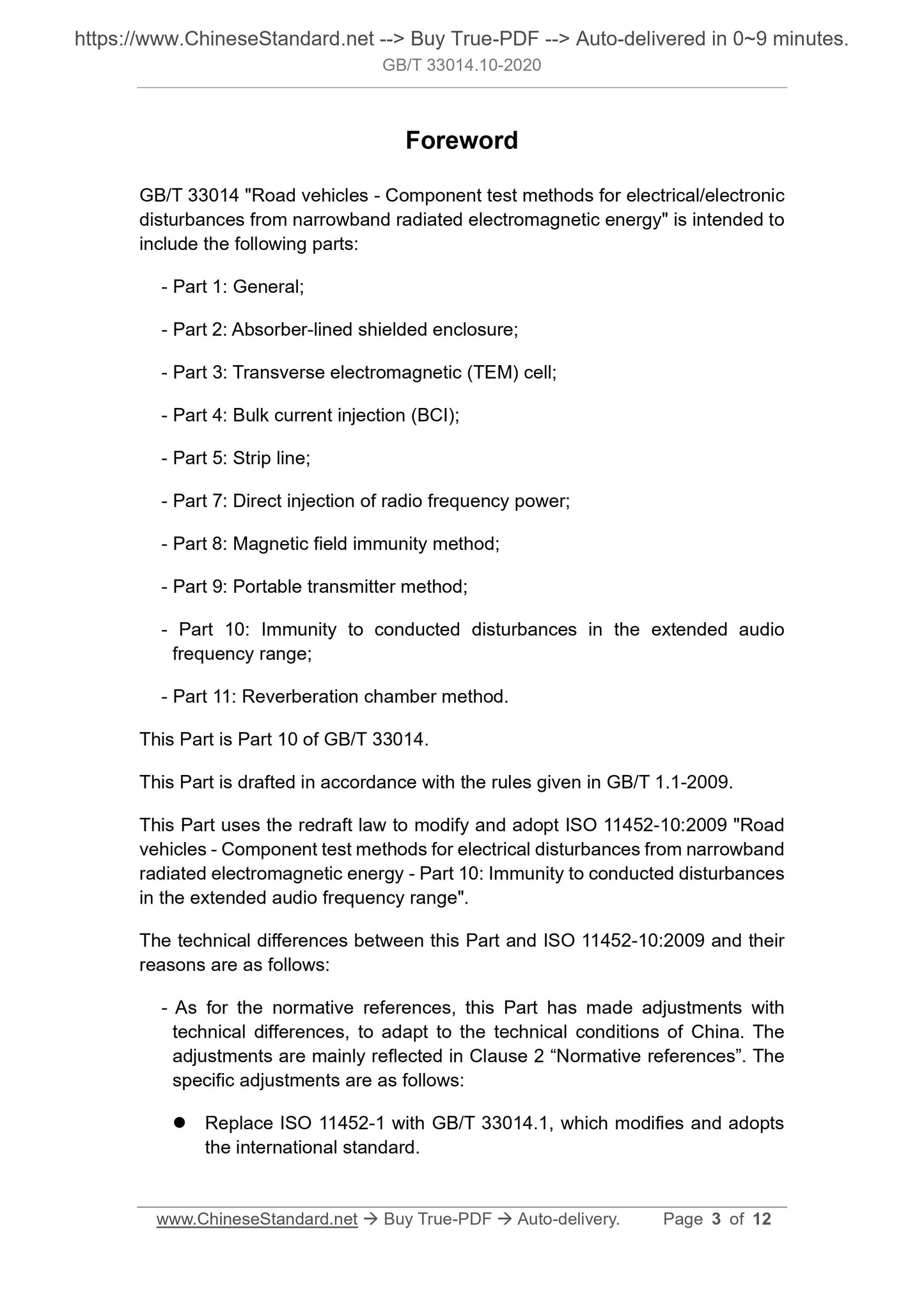
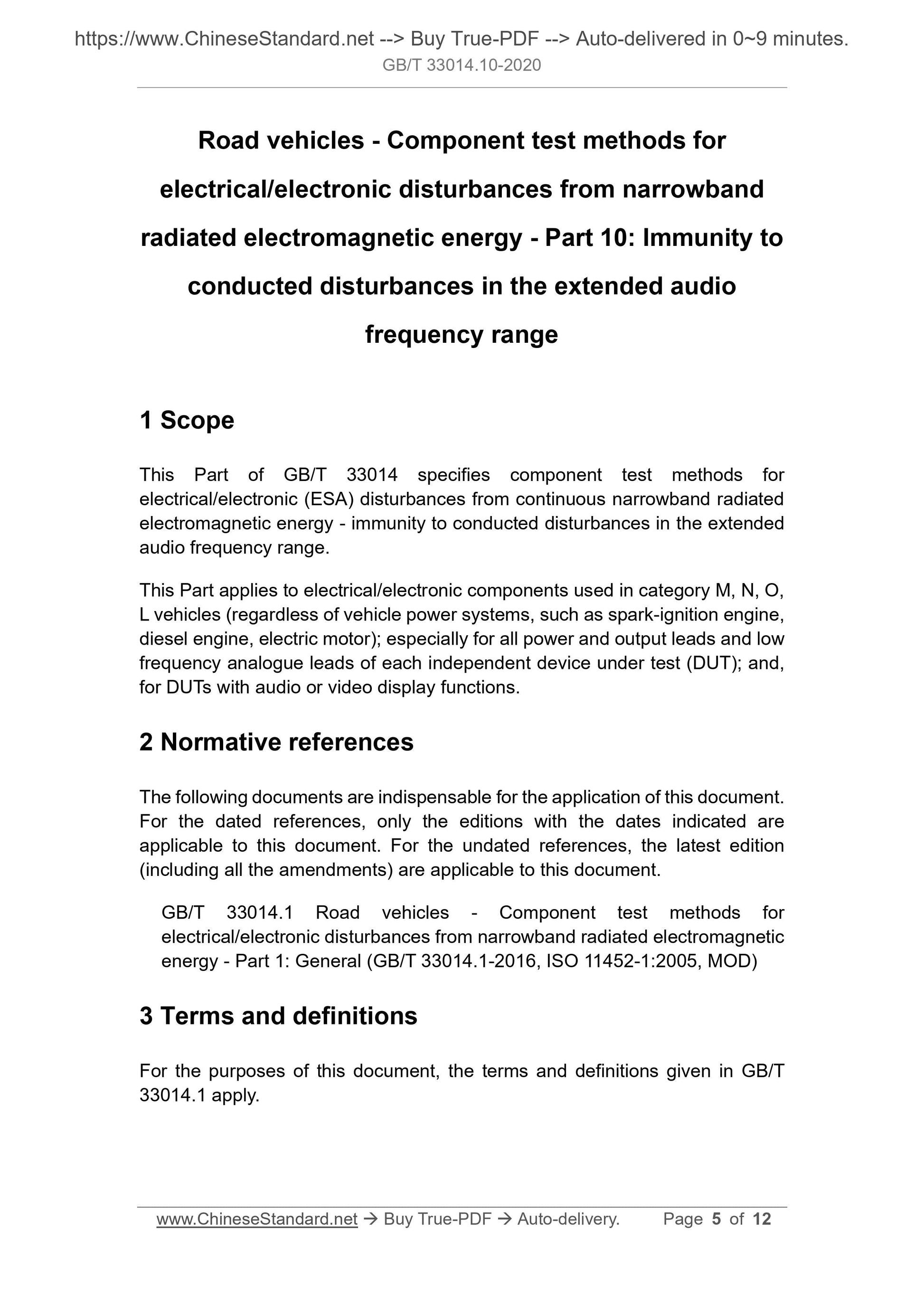
Foreword
GB/T 33014 "Road vehicles - Component test methods for electrical/electronic
disturbances from narrowband radiated electromagnetic energy" is intended to
include the following parts:
- Part 1: General;
- Part 2: Absorber-lined shielded enclosure;
- Part 3: Transverse electromagnetic (TEM) cell;
- Part 4: Bulk current injection (BCI);
- Part 5: Strip line;
- Part 7: Direct injection of radio frequency power;
- Part 8: Magnetic field immunity method;
- Part 9: Portable transmitter method;
- Part 10: Immunity to conducted disturbances in the extended audio
frequency range;
- Part 11: Reverberation chamber method.
This Part is Part 10 of GB/T 33014.
This Part is drafted in accordance with the rules given in GB/T 1.1-2009.
This Part uses the redraft law to modify and adopt ISO 11452-10:2009 "Road
vehicles - Component test methods for electrical disturbances from narrowband
radiated electromagnetic energy - Part 10: Immunity to conducted disturbances
in the extended audio frequency range".
The technical differences between this Part and ISO 11452-10:2009 and their
reasons are as follows:
- As for the normative references, this Part has made adjustments with
technical differences, to adapt to the technical conditions of China. The
adjustments are mainly reflected in Clause 2 “Normative references”. The
specific adjustments are as follows:
Replace ISO 11452-1 with GB/T 33014.1, which modifies and adopts
the international standard.
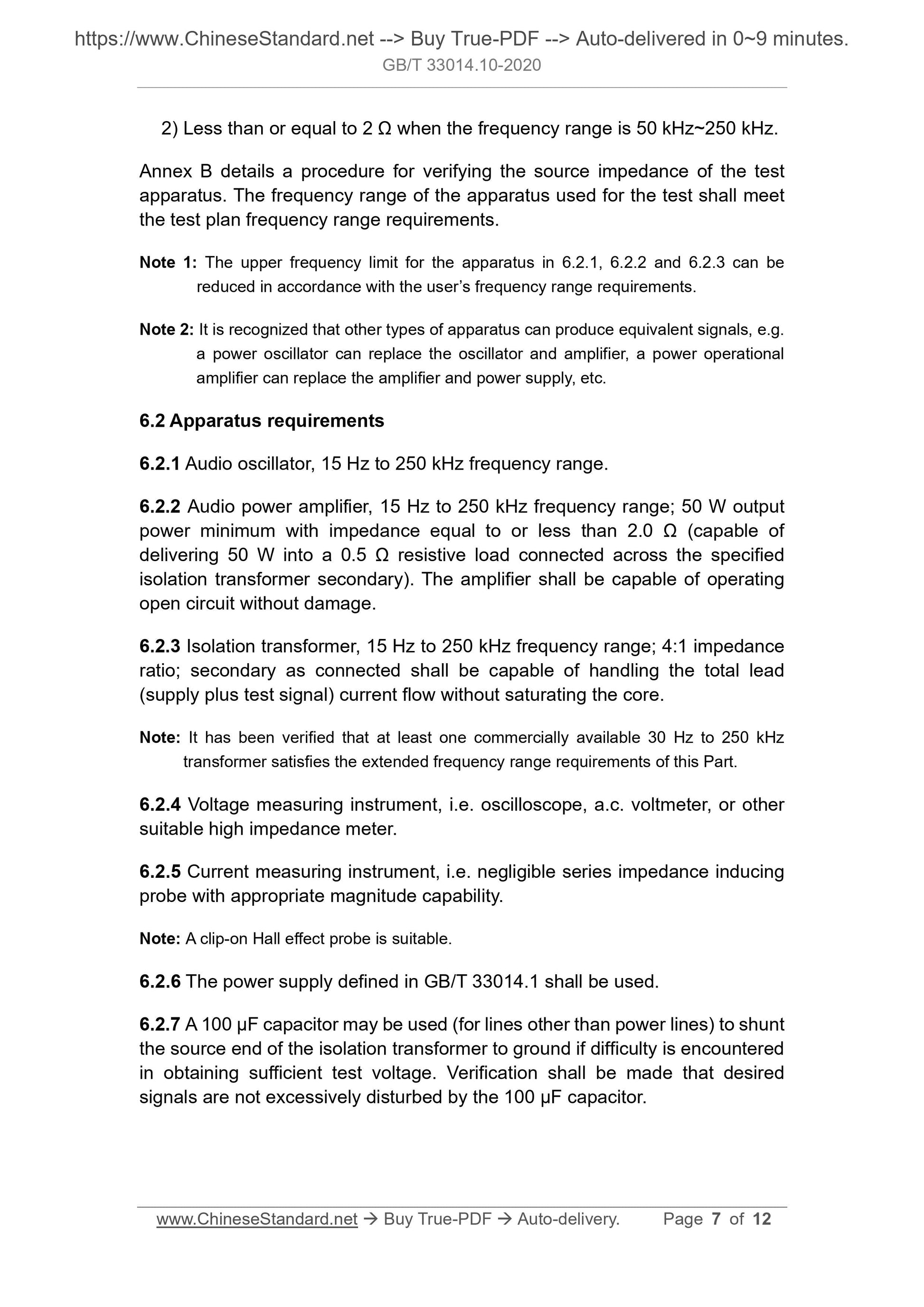
Road vehicles - Component test methods for
electrical/electronic disturbances from narrowband
radiated electromagnetic energy - Part 10: Immunity to
conducted disturbances in the extended audio
frequency range
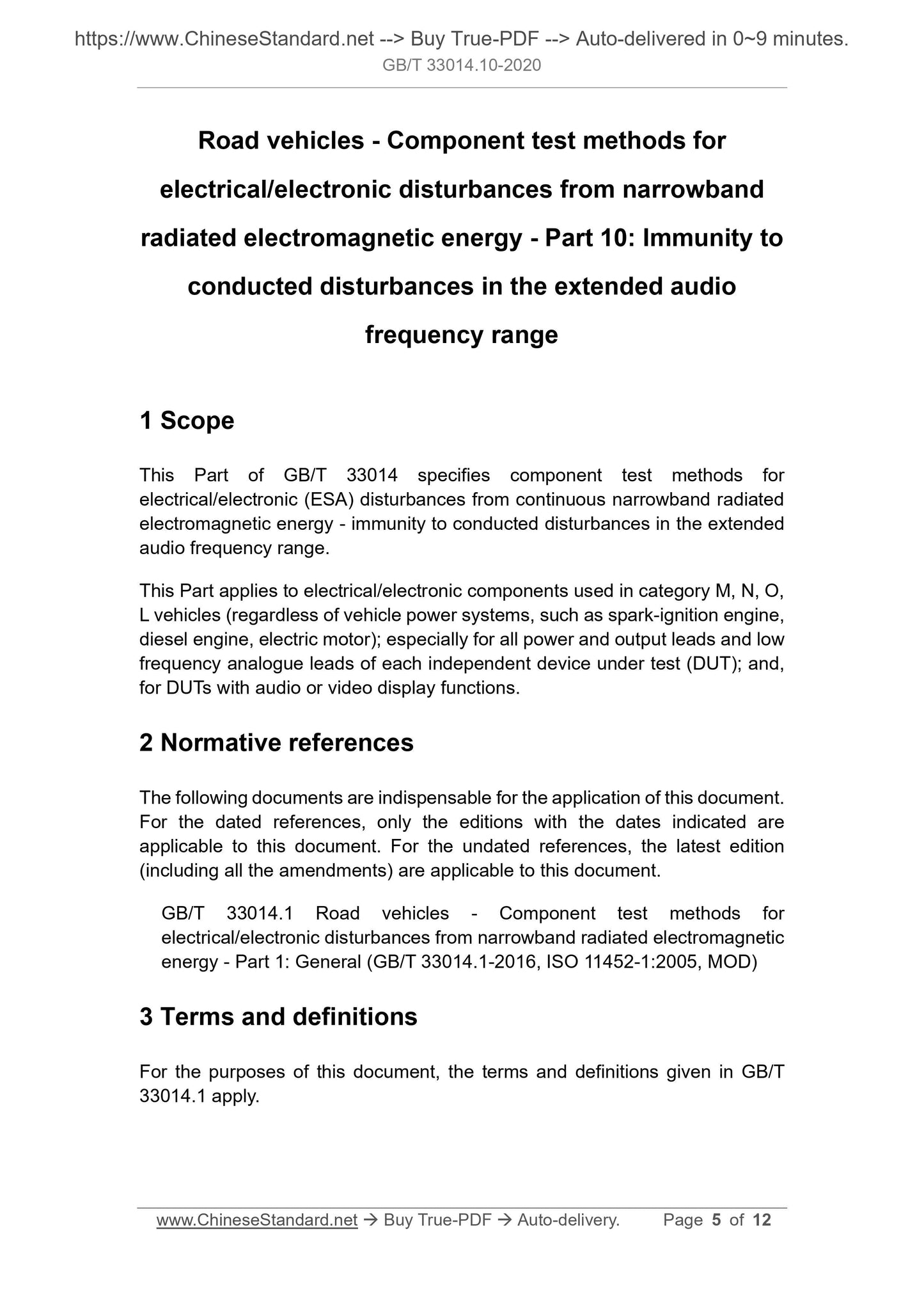
1 Scope
This Part of GB/T 33014 specifies component test methods for
electrical/electronic (ESA) disturbances from continuous narrowband radiated
electromagnetic energy - immunity to conducted disturbances in the extended
audio frequency range.
This Part applies to electrical/electronic components used in category M, N, O,
L vehicles (regardless of vehicle power systems, such as spark-ignition engine,
diesel engine, electric motor); especially for all power and output leads and low
frequency analogue leads of each independent device under test (DUT); and,
for DUTs with audio or video display functions.
2 Normative references
The following documents are indispensable for the application of this document.
For the dated references, only the editions with the dates indicated are
applicable to this document. For the undated references, the latest edition
(including all the amendments) are applicable to this document.
GB/T 33014.1 Road vehicles - Component test methods for
electrical/electronic disturbances from narrowband radiated electromagnetic
energy - Part 1: General (GB/T 33014.1-2016, ISO 11452-1:2005, MOD)
3 Terms and definitions
For the purposes of this document, the terms and definitions given in GB/T
33014.1 apply.
2) Less than or equal to 2 Ω when the frequency range is 50 kHz~250 kHz.
Annex B details a procedure for verifying the source impedance of the test
apparatus. The frequency range of the apparatus used for the test shall meet
the test plan frequency range requirements.
Note 1: The upper frequency limit for the apparatus in 6.2.1, 6.2.2 and 6.2.3 can be
reduced in accordance with the user’s frequency range requirements.
Note 2: It is recognized that other types of apparatus can produce equivalent signals, e.g.
a power oscillator can replace the oscillator and amplifier, a power operational
amplifier can replace the amplifier and power supply, etc.
6.2 Apparatus requirements
6.2.1 Audio oscillator, 15 Hz to 250 kHz frequency range.
6.2.2 Audio power amplifier, 15 Hz to 250 kHz frequency range; 50 W output
power minimum with impedance equal to or less than 2.0 Ω (capable of
delivering 50 W into a 0.5 Ω resistive load connected across the specified
isolation transformer secondary). The amplifier shall be capable of operating
open circuit without damage.
6.2.3 Isolation transformer, 15 Hz to 250 kHz frequency range; 4:1 impedance
ratio; secondary as connected shall be capable of handling the total lead
(supply plus test signal) current flow without saturating the core.
Note: It has been verified that at least one commercially available 30 Hz to 250 kHz
transformer satisfies the extended frequency range requirements of this Part.
6.2.4 Voltage measuring instrument, i.e. oscilloscope, a.c. voltmeter, or other
suitable high impedance meter.
6.2.5 Current measuring instrument, i.e. negligible series impedance inducing
probe with appropriate magnitude capability.
Note: A clip-on Hall effect probe is suitable.
6.2.6 The power supply defined in GB/T 33014.1 shall be used.
6.2.7 A 100 μF capacitor may be used (for lines other than power lines) to shunt
the source end of the isolation transformer to ground if difficulty is encountered
in obtaining sufficient test voltage. Verification shall be made that desired
signals are not excessively disturbed by the 100 μF capacitor.
During the test, filters incorporated into DUTs may experience excessive and
potentially damaging current flow. To prevent this type of over stress in the DUT,
a current probe is included in the test set-up.
The impedance characteristics of the DUT line being tested may cause
distortion to the test signal. This complicates the use of an a.c. voltmeter. A
method of addressing this phenomenon is included in the test procedures.
8.2 Test plan
Prior to performing the tests, a test plan shall be generated which shall include:
- Test set-up;
- Frequency range;
- Test frequencies or step sizes;
- DUT leads to be tested;
- DUT mode of operation;
- DUT acceptance criteria;
- Test severity levels;
- DUT monitoring conditions;
- Test report content.
8.3 Test procedure
8.3.1 Power supply voltage
The system power supply voltage shall be set as specified in the test plan and
shall be measured at the DUT to account for voltage drop in the isolation
transformer secondary winding.
Note: The voltage drop across the transformer secondary winding can become significant
at higher currents.
8.3.2 Audio oscillator
The audio oscillator shall be tuned through the required frequency range as
specified in the test plan.
8.3.3 Test signal inj...
Share
