


1
/
of
12
PayPal, credit cards. Download editable-PDF and invoice in 1 second!
GB/T 33014.11-2023 English PDF (GB/T33014.11-2023)
GB/T 33014.11-2023 English PDF (GB/T33014.11-2023)
Regular price
$405.00 USD
Regular price
Sale price
$405.00 USD
Unit price
/
per
Shipping calculated at checkout.
Couldn't load pickup availability
Delivery: 3 seconds. Download true-PDF + Invoice.
Get Quotation: Click GB/T 33014.11-2023 (Self-service in 1-minute)
Historical versions (Master-website): GB/T 33014.11-2023
Preview True-PDF (Reload/Scroll-down if blank)
GB/T 33014.11-2023: Road vehicles - Component test methods for electrical/ electronic disturbances from narrowband radiated electromagnetic energy - Part 11: Reverberation chamber
GB/T 33014.11-2023
GB
NATIONAL STANDARD OF THE
PEOPLE’S REPUBLIC OF CHINA
ICS 43.040.10
CCS T 36
Road vehicles - Component test methods for electrical /
electronic disturbances from narrowband radiated
electromagnetic energy - Part 11: Reverberation chamber
(ISO 11452-11:2010, Road vehicles - Component test methods for electrical
disturbances from narrowband radiated electromagnetic energy - Part 11:
Reverberation chamber, MOD)
ISSUED ON: SEPTEMBER 07, 2023
IMPLEMENTED ON: APRIL 01, 2024
Issued by: State Administration for Market Regulation;
Standardization Administration of the People’s Republic of China.
Table of Contents
Foreword ... 4
Introduction ... 6
1 Scope ... 8
2 Normative references ... 8
3 Terms and definitions ... 8
4 Test conditions ... 10
5 Test locations ... 11
5.1 General ... 11
5.2 Reverberation chamber ... 11
6 Test equipment and instruments ... 11
6.1 Isotropic electric field probe ... 11
6.2 RF signal source ... 12
6.3 Transmitting and receiving antennas ... 12
6.4 Power amplifier ... 12
6.5 Spectrum analyzer ... 12
6.6 Directional coupler ... 12
6.7 Power meter ... 12
6.8 Computer control ... 12
6.9 DUT actuator and monitoring equipment ... 13
7 Test layout ... 13
7.1 General ... 13
7.2 Ground plane and DUT grounding ... 13
7.3 Power and artificial network (AN) ... 14
7.4 Location of DUT and wiring harness ... 15
7.5 Location of artificial load ... 15
7.6 Location of transmitting antenna ... 15
7.7 Location of receiving antenna ... 16
8 Test methods ... 17
8.1 Test plan ... 17
8.2 Test procedures ... 18
8.3 Test report ... 20
Annex A (Informative) Function performance status classification (FPSC) ... 21
A.1 General ... 21
A.2 Severity levels ... 21
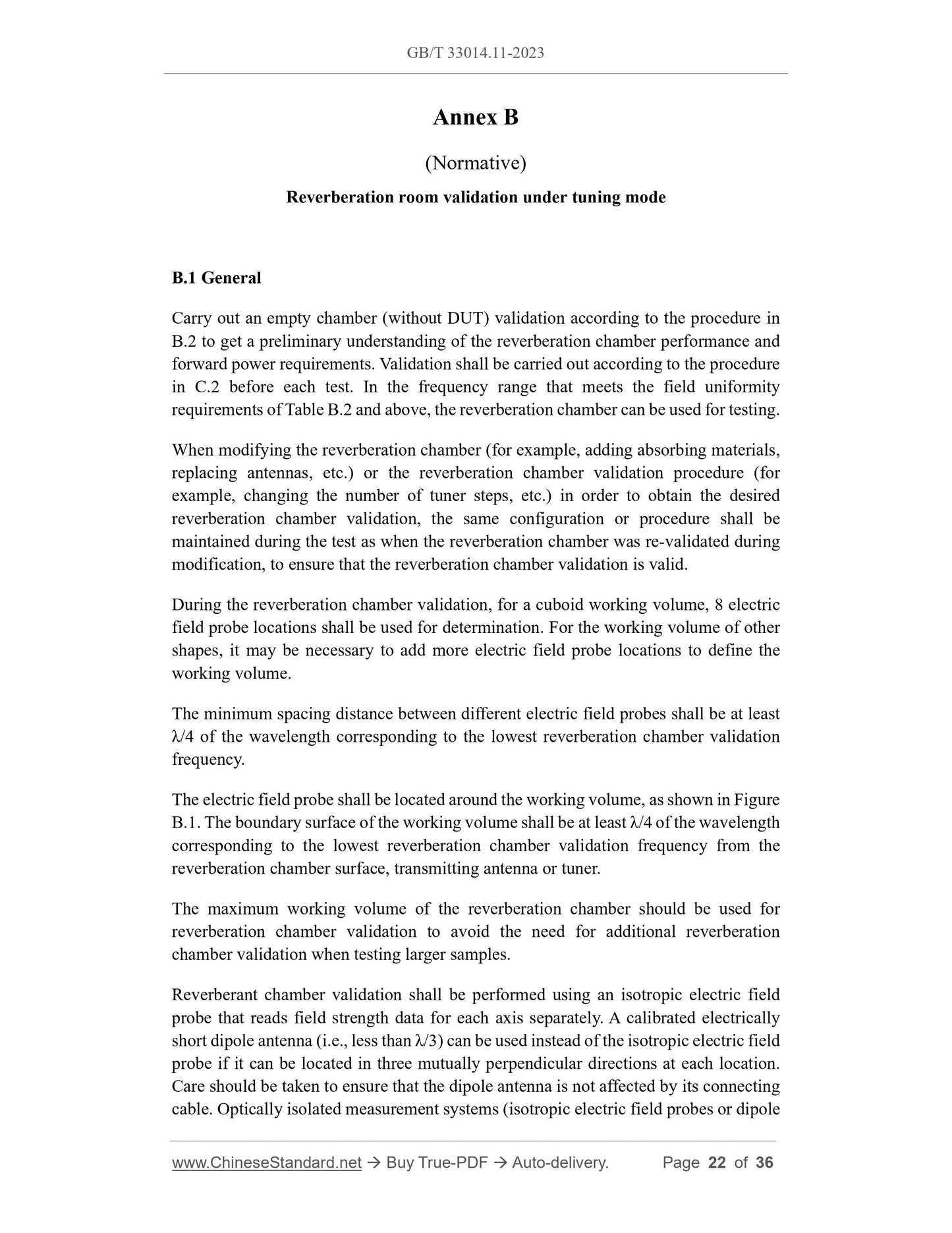
Annex B (Normative) Reverberation room validation under tuning mode ... 22
B.1 General ... 22
B.2 Test procedures ... 24
B.3 Reverberation chamber gain ... 25
B.4 Field uniformity ... 26
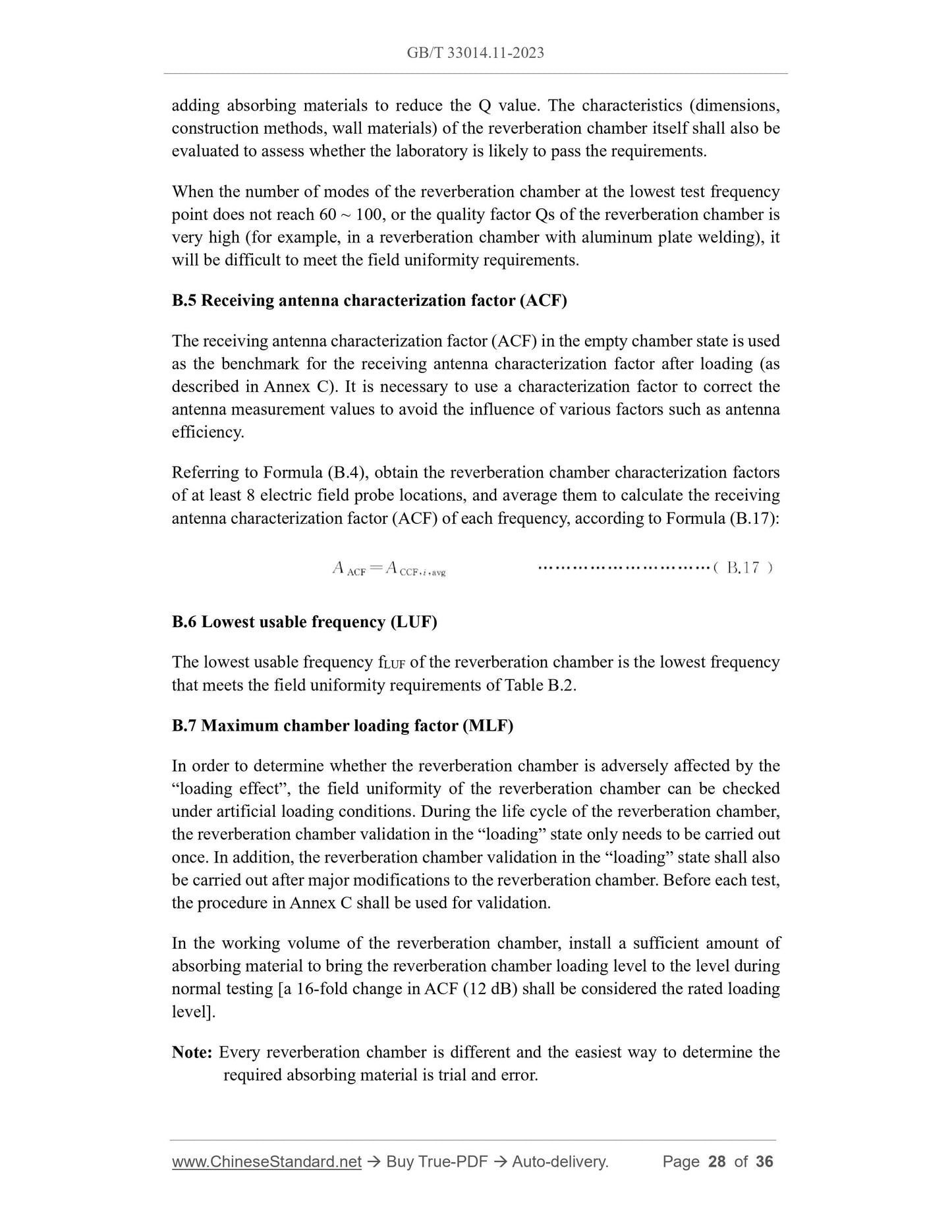
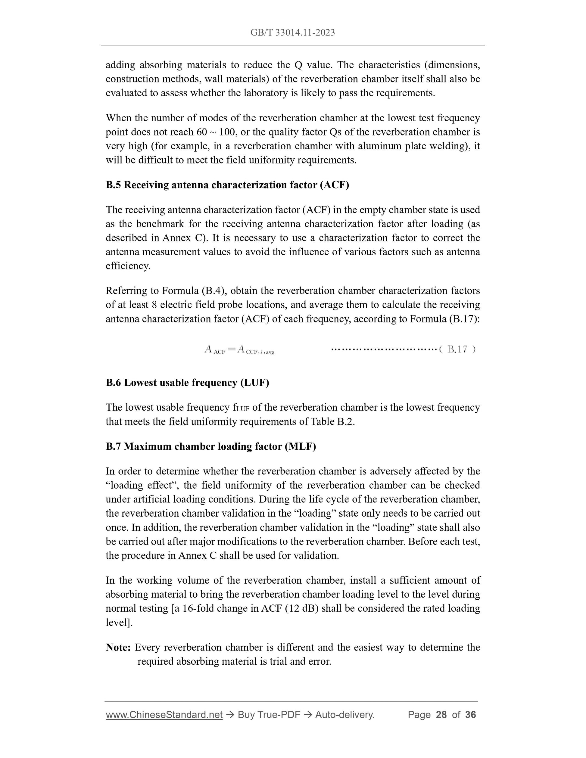
B.5 Receiving antenna characterization factor (ACF) ... 28
B.6 Lowest usable frequency (LUF) ... 28
B.7 Maximum chamber loading factor (MLF) ... 28
Annex C (Normative) Loading effect calibration of reverberation chamber... 30
C.1 General ... 30
C.2 Test procedures ... 30
C.3 Chamber characterization factor ... 31
C.4 Chamber loading factor ... 31
C.5 Minimum pulse width ... 32
Annex D (Normative) Artificial network (AN) ... 34
D.1 General ... 34
D.2 Impedance of AN ... 34
Bibliography ... 36
Road vehicles - Component test methods for electrical /
electronic disturbances from narrowband radiated
electromagnetic energy - Part 11: Reverberation chamber
1 Scope
This document establishes the immunity test method for vehicle electrical/electronic
components to continuous narrowband radiated electromagnetic disturbance –
reverberation chamber.
This document establishes the test method for applying electromagnetic interference to
the device under test (hereinafter referred to as DUT) and the wiring harness (real
vehicle wiring harness or standard test wiring harness) in the reverberation chamber.
During the test, the support equipment of the DUT can be arranged either inside the
reverberation chamber or outside the reverberation room. The test shall be performed
under the tuning mode.
This document applies to the immunity test of electrical/electronic components for M,
N, O, and L category vehicles (not limited to vehicle power systems, such as spark
ignition engines, diesel engines, and electric motors).
2 Normative references
The following documents are referred to in the text in such a way that some or all of
their content constitutes requirements of this document. For dated references, only the
version corresponding to that date is applicable to this document; for undated references,
the latest version (including all amendments) is applicable to this document.
GB/T 33014.1, Road vehicles - Component test methods for electrical/electronic
disturbances from narrowband radiated electromagnetic energy - Part 1: General
(GB/T 33014.1-2016, ISO 11452-1:2005, MOD)
3 Terms and definitions
Terms and definitions determined by GB/T 33014.1, and the following ones are
applicable to this document.
3.1
antenna characterization factor; ACF
-- test temperature;
-- test voltage;
-- modulation system;
-- dwell time;
-- test signal quality.
5 Test locations
5.1 General
The test shall be carried out in a reverberation chamber.
5.2 Reverberation chamber
The reverberation chamber used to test the DUT shall be so large that its working
volume can accommodate the test bench, support equipment and receiving antennas.
Note 1: Reverberation chamber size will affect the lowest usable frequency (LUF).
The working volume is usually rectangular which, however, is not essential.
The reverberation chamber shall contain at least one mechanical tuner to stir the
electromagnetic field in the chamber. Based on the reverberation chamber size and
working volume, the size of the mechanical tuner shall be as large as possible. In
addition, the shape of each tuner shall be such that during one rotation, the reverberation
chamber obtains a non-repetitive field distribution.
Note 2: The number, size and shape of tuners will affect the lowest usable frequency
(LUF).
After the reverberation chamber is built, the reverberation chamber validation shall be
performed according to Annex B. The field uniformity shall meet the requirements of
Table B.2, and the LUF of the reverberation chamber shall be confirmed. After any
major renovation, reverberation chamber validation shall be performed again. Tuner
changes shall be considered a major modification.
6 Test equipment and instruments
6.1 Isotropic electric field probe
The electric field probe shall be able to measure the electrical field strength on three
orthogonal axes.
6.2 RF signal source
The RF signal source shall be able to cover the specified frequency range and
modulation system.
6.3 Transmitting and receiving antennas
Linear polarizing antennas that meet the transmitting and receiving frequency
requirements respectively shall be used. Antenna efficiency shall be at least 75% (log-
periodic antennas and horn antennas usually meet this requirement). It is allowable to
use multiple antennas to cover the entire frequency range of the reverberation chamber.
6.4 Power amplifier
Power amplifiers are used to amplify radio frequency signals and provide the necessary
power to the transmitting antenna to generate the specified field strength.
6.5 Spectrum analyzer
The spectrum analyzer shall be able to cover the specified frequency range. Confirm
and test the reverberation chamber using a spectrum analyzer and receiving antenna
with and without a DUT.
6.6 Directional coupler
The directional coupler shall be able to cover the specified frequency range. It shall be
able to withstand the RF output of the power amplifier without damage. The directional
coupler is used in conjunction with the power meter to measure the forward power
delivered to the transmitting antenna.
6.7 Power meter
The power meter shall be able to cover the specified frequency range. The power meter
is used in conjunction with the directional coupler to measure the forward power
delivered to the transmitting antenna.
6.8 Computer control
The computer control system shall have the following functions: Before the DUT test,
special software combined with the computer and radio frequency test equipment needs
to be used for reverberation chamber validation according to Annex B. The software
needs to store the reverberation chamber validation information for use during the test.
During the DUT test, the software shall be able to control the RF test equipment and
tuner for testing as described in Chapter 8.
If the DUT’s enclosure is grounded to the vehicle’s metal structure, the DUT enclosure
should be grounded during the test (either through a ground plane or through a ground
plate placed on the test bench). The ground state of the DUT enclosure shall simulate
the actual vehicle configuration.
The ground plane (if used) of the test bench shall be made of copper, brass or galvanized
steel. The minimum size of the ground plane depends on the size of the system under
test and shall be able to fully accommodate the wiring harness and DUT system
components. The ground plane (excluding the ground connection) shall be placed
within the working volume of the reverberation chamber at a minimum distance of λ/4
corresponding to the lowest usable frequency from any walls and the tuner. The ground
plane shall be connected to the reverberation chamber using a ground strap, and its DC
resistance shall not exceed 2.5 mΩ. In addition, the edge distance between ground strips
shall not be greater than 0.3 m.
Note: Using a ground surface as the ground plane is an alternative currently under
investigation.
7.3 Power and artificial network (AN)
When DC power is required to maintain battery voltage, the DC power source shall be
located outside the reverberation chamber. All power lines entering the reverberation
chamber shall be filtered. The DC power line used to maintain the battery voltage can
be shielded from the reverberation chamber filter to the battery connecting point. The
DC power leads in the reverberation chamber should be routed along the walls and
reverberation chamber floor to minimize field coupling of the leads.
AN shall not be used if a ground plane is not used. The DUT’s power cord shall be
connected directly to the battery terminals.
If a ground plane is used, each power cord shall be connected to the power source via
AN. The DUT shall be powered through 5 μH/50Ω AN. Annex D gives the schematic
circuit diagram of artificial network (AN). The number of ANs required depends on
how the DUT is expected to be installed in the vehicle.
-- DUT far-end grounding (vehicle power return wire larger than 200 mm): Use two
ANs, one of which is connected to the positive pole of the power supply, and the
other is connected to the power return wire. The negative terminal of the power
supply shall be connected to the ground plane on the AN power (input) side of
the return wire.
-- DUT near-end grounding (vehicle power return wire not larger than 200 mm): Use
an AN and connect it to the positive pole of the power supply. The DUT power
return wire shall not be larger than 200 mm and shall be connected to the ground
plane. The negative terminal of the power supply shall be connected to a ground
plane near the AN enclosure ground.
AN shall be installed directly on the ground plane, and the housing shall overlap the
ground plane.
The measurement port of each AN shall be connected to a 50 Ω load.
7.4 Location of DUT and wiring harness
Unless otherwise specified in the test plan, a wiring harness of 1 700+300 0 mm length
shall be used. The type of wiring harness should be determined according to the actual
system usage (shielded, unshielded, twisted pair, etc.). The length of the wiring harness
shall be recorded in the test report.
The wiring harness shall be arranged in a “U shape” so that the straight length of the
wiring harness between the DUT and the artificial load is (1500±75) mm. The wiring
harness bending angle shall be (90+45 0 ) °.
If a ground plane is used, the DUT and wiring harness shall be placed (50±5) mm above
the ground plane on a non-conductive, low-dielectric-constant material (relative
dielectric constant, εr ≤ 1.4).
7.5 Location of artificial load
If a ground plane is used, the artificial load should be placed directly on the ground
plane. If the artificial load is a metal enclosure, the enclosure shall be directly connected
to the ground plane.
The artificial load can be arranged near the reference ground plane (the artificial load
enclosure overlaps the ground plane) or the artificial load can be arranged outside the
reverberation chamber. At this time, the test harness of the DUT passes through the RF
boundary that overlaps the reference ground plane.
When the artificial load is placed on a ground plane, the DC power line of the artificial
load shall be connected through AN.
7.6 Location of transmitting antenna
The location of the transmitting antenna shall remain unchanged during reverberation
chamber validation and testing. The transmitting antenna shall not illuminate the
working volume directly. If possible, the transmitting antenna shall be pointed at a
certain corner of the reverberation chamber (see Figure 1 for the location of the
transmitting antenna), or at the tuner. The transmitting antenna should be supported by
a non-conductive support (e.g., non-conductive tripod or polystyrene clamp) and kept
at a distance of at least λ/4 corresponding to the lowest usable frequency from any walls
and corners.
Note: Tilt the antenna upward to avoid the incident wave vertically irradiating the
reverberation chamber wall, which causes the standing wave ratio to be too high.
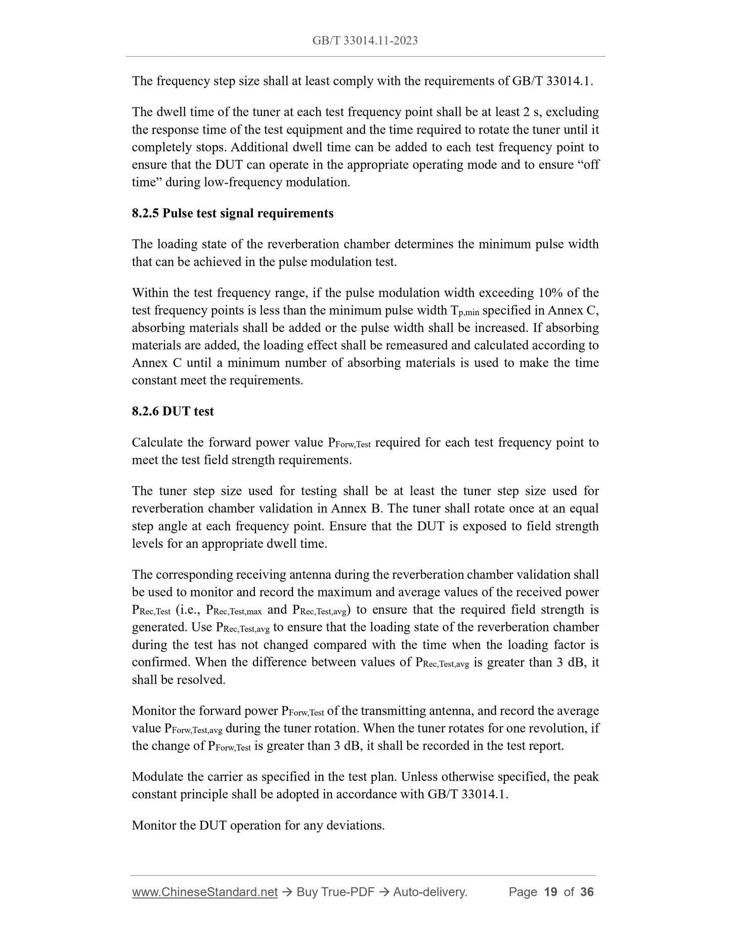
The frequency step size shall at least comply with the requirements of GB/T 33014.1.
The dwell time of the tuner at each test frequency point shall be at least 2 s, excluding
the response time of the test equipment and the time required to rotate the tuner until it
completely stops. Additional dwell time can be added to each test frequency point to
ensure that the DUT can operate in the appropriate operating mode and to ensure “off
time” during low-frequency modulation.
8.2.5 Pulse test signal requirements
The loading state of the reverberation chamber determines the minimum pulse width
that can be achieved in the pulse modulation test.
Within the test frequency range, if the pulse modulation width exceeding 10% of the
test frequency points is less than the minimum pulse width Tp,min specified in Annex C,
absorbing materials shall be added or the pulse width shall be increased. If absorbing
materials are added, the loading effect shall be remeasured an...
Get Quotation: Click GB/T 33014.11-2023 (Self-service in 1-minute)
Historical versions (Master-website): GB/T 33014.11-2023
Preview True-PDF (Reload/Scroll-down if blank)
GB/T 33014.11-2023: Road vehicles - Component test methods for electrical/ electronic disturbances from narrowband radiated electromagnetic energy - Part 11: Reverberation chamber
GB/T 33014.11-2023
GB
NATIONAL STANDARD OF THE
PEOPLE’S REPUBLIC OF CHINA
ICS 43.040.10
CCS T 36
Road vehicles - Component test methods for electrical /
electronic disturbances from narrowband radiated
electromagnetic energy - Part 11: Reverberation chamber
(ISO 11452-11:2010, Road vehicles - Component test methods for electrical
disturbances from narrowband radiated electromagnetic energy - Part 11:
Reverberation chamber, MOD)
ISSUED ON: SEPTEMBER 07, 2023
IMPLEMENTED ON: APRIL 01, 2024
Issued by: State Administration for Market Regulation;
Standardization Administration of the People’s Republic of China.
Table of Contents
Foreword ... 4
Introduction ... 6
1 Scope ... 8
2 Normative references ... 8
3 Terms and definitions ... 8
4 Test conditions ... 10
5 Test locations ... 11
5.1 General ... 11
5.2 Reverberation chamber ... 11
6 Test equipment and instruments ... 11
6.1 Isotropic electric field probe ... 11
6.2 RF signal source ... 12
6.3 Transmitting and receiving antennas ... 12
6.4 Power amplifier ... 12
6.5 Spectrum analyzer ... 12
6.6 Directional coupler ... 12
6.7 Power meter ... 12
6.8 Computer control ... 12
6.9 DUT actuator and monitoring equipment ... 13
7 Test layout ... 13
7.1 General ... 13
7.2 Ground plane and DUT grounding ... 13
7.3 Power and artificial network (AN) ... 14
7.4 Location of DUT and wiring harness ... 15
7.5 Location of artificial load ... 15
7.6 Location of transmitting antenna ... 15
7.7 Location of receiving antenna ... 16
8 Test methods ... 17
8.1 Test plan ... 17
8.2 Test procedures ... 18
8.3 Test report ... 20
Annex A (Informative) Function performance status classification (FPSC) ... 21
A.1 General ... 21
A.2 Severity levels ... 21
Annex B (Normative) Reverberation room validation under tuning mode ... 22
B.1 General ... 22
B.2 Test procedures ... 24
B.3 Reverberation chamber gain ... 25
B.4 Field uniformity ... 26
B.5 Receiving antenna characterization factor (ACF) ... 28
B.6 Lowest usable frequency (LUF) ... 28
B.7 Maximum chamber loading factor (MLF) ... 28
Annex C (Normative) Loading effect calibration of reverberation chamber... 30
C.1 General ... 30
C.2 Test procedures ... 30
C.3 Chamber characterization factor ... 31
C.4 Chamber loading factor ... 31
C.5 Minimum pulse width ... 32
Annex D (Normative) Artificial network (AN) ... 34
D.1 General ... 34
D.2 Impedance of AN ... 34
Bibliography ... 36
Road vehicles - Component test methods for electrical /
electronic disturbances from narrowband radiated
electromagnetic energy - Part 11: Reverberation chamber
1 Scope
This document establishes the immunity test method for vehicle electrical/electronic
components to continuous narrowband radiated electromagnetic disturbance –
reverberation chamber.
This document establishes the test method for applying electromagnetic interference to
the device under test (hereinafter referred to as DUT) and the wiring harness (real
vehicle wiring harness or standard test wiring harness) in the reverberation chamber.
During the test, the support equipment of the DUT can be arranged either inside the
reverberation chamber or outside the reverberation room. The test shall be performed
under the tuning mode.
This document applies to the immunity test of electrical/electronic components for M,
N, O, and L category vehicles (not limited to vehicle power systems, such as spark
ignition engines, diesel engines, and electric motors).
2 Normative references
The following documents are referred to in the text in such a way that some or all of
their content constitutes requirements of this document. For dated references, only the
version corresponding to that date is applicable to this document; for undated references,
the latest version (including all amendments) is applicable to this document.
GB/T 33014.1, Road vehicles - Component test methods for electrical/electronic
disturbances from narrowband radiated electromagnetic energy - Part 1: General
(GB/T 33014.1-2016, ISO 11452-1:2005, MOD)
3 Terms and definitions
Terms and definitions determined by GB/T 33014.1, and the following ones are
applicable to this document.
3.1
antenna characterization factor; ACF
-- test temperature;
-- test voltage;
-- modulation system;
-- dwell time;
-- test signal quality.
5 Test locations
5.1 General
The test shall be carried out in a reverberation chamber.
5.2 Reverberation chamber
The reverberation chamber used to test the DUT shall be so large that its working
volume can accommodate the test bench, support equipment and receiving antennas.
Note 1: Reverberation chamber size will affect the lowest usable frequency (LUF).
The working volume is usually rectangular which, however, is not essential.
The reverberation chamber shall contain at least one mechanical tuner to stir the
electromagnetic field in the chamber. Based on the reverberation chamber size and
working volume, the size of the mechanical tuner shall be as large as possible. In
addition, the shape of each tuner shall be such that during one rotation, the reverberation
chamber obtains a non-repetitive field distribution.
Note 2: The number, size and shape of tuners will affect the lowest usable frequency
(LUF).
After the reverberation chamber is built, the reverberation chamber validation shall be
performed according to Annex B. The field uniformity shall meet the requirements of
Table B.2, and the LUF of the reverberation chamber shall be confirmed. After any
major renovation, reverberation chamber validation shall be performed again. Tuner
changes shall be considered a major modification.
6 Test equipment and instruments
6.1 Isotropic electric field probe
The electric field probe shall be able to measure the electrical field strength on three
orthogonal axes.
6.2 RF signal source
The RF signal source shall be able to cover the specified frequency range and
modulation system.
6.3 Transmitting and receiving antennas
Linear polarizing antennas that meet the transmitting and receiving frequency
requirements respectively shall be used. Antenna efficiency shall be at least 75% (log-
periodic antennas and horn antennas usually meet this requirement). It is allowable to
use multiple antennas to cover the entire frequency range of the reverberation chamber.
6.4 Power amplifier
Power amplifiers are used to amplify radio frequency signals and provide the necessary
power to the transmitting antenna to generate the specified field strength.
6.5 Spectrum analyzer
The spectrum analyzer shall be able to cover the specified frequency range. Confirm
and test the reverberation chamber using a spectrum analyzer and receiving antenna
with and without a DUT.
6.6 Directional coupler
The directional coupler shall be able to cover the specified frequency range. It shall be
able to withstand the RF output of the power amplifier without damage. The directional
coupler is used in conjunction with the power meter to measure the forward power
delivered to the transmitting antenna.
6.7 Power meter
The power meter shall be able to cover the specified frequency range. The power meter
is used in conjunction with the directional coupler to measure the forward power
delivered to the transmitting antenna.
6.8 Computer control
The computer control system shall have the following functions: Before the DUT test,
special software combined with the computer and radio frequency test equipment needs
to be used for reverberation chamber validation according to Annex B. The software
needs to store the reverberation chamber validation information for use during the test.
During the DUT test, the software shall be able to control the RF test equipment and
tuner for testing as described in Chapter 8.
If the DUT’s enclosure is grounded to the vehicle’s metal structure, the DUT enclosure
should be grounded during the test (either through a ground plane or through a ground
plate placed on the test bench). The ground state of the DUT enclosure shall simulate
the actual vehicle configuration.
The ground plane (if used) of the test bench shall be made of copper, brass or galvanized
steel. The minimum size of the ground plane depends on the size of the system under
test and shall be able to fully accommodate the wiring harness and DUT system
components. The ground plane (excluding the ground connection) shall be placed
within the working volume of the reverberation chamber at a minimum distance of λ/4
corresponding to the lowest usable frequency from any walls and the tuner. The ground
plane shall be connected to the reverberation chamber using a ground strap, and its DC
resistance shall not exceed 2.5 mΩ. In addition, the edge distance between ground strips
shall not be greater than 0.3 m.
Note: Using a ground surface as the ground plane is an alternative currently under
investigation.
7.3 Power and artificial network (AN)
When DC power is required to maintain battery voltage, the DC power source shall be
located outside the reverberation chamber. All power lines entering the reverberation
chamber shall be filtered. The DC power line used to maintain the battery voltage can
be shielded from the reverberation chamber filter to the battery connecting point. The
DC power leads in the reverberation chamber should be routed along the walls and
reverberation chamber floor to minimize field coupling of the leads.
AN shall not be used if a ground plane is not used. The DUT’s power cord shall be
connected directly to the battery terminals.
If a ground plane is used, each power cord shall be connected to the power source via
AN. The DUT shall be powered through 5 μH/50Ω AN. Annex D gives the schematic
circuit diagram of artificial network (AN). The number of ANs required depends on
how the DUT is expected to be installed in the vehicle.
-- DUT far-end grounding (vehicle power return wire larger than 200 mm): Use two
ANs, one of which is connected to the positive pole of the power supply, and the
other is connected to the power return wire. The negative terminal of the power
supply shall be connected to the ground plane on the AN power (input) side of
the return wire.
-- DUT near-end grounding (vehicle power return wire not larger than 200 mm): Use
an AN and connect it to the positive pole of the power supply. The DUT power
return wire shall not be larger than 200 mm and shall be connected to the ground
plane. The negative terminal of the power supply shall be connected to a ground
plane near the AN enclosure ground.
AN shall be installed directly on the ground plane, and the housing shall overlap the
ground plane.
The measurement port of each AN shall be connected to a 50 Ω load.
7.4 Location of DUT and wiring harness
Unless otherwise specified in the test plan, a wiring harness of 1 700+300 0 mm length
shall be used. The type of wiring harness should be determined according to the actual
system usage (shielded, unshielded, twisted pair, etc.). The length of the wiring harness
shall be recorded in the test report.
The wiring harness shall be arranged in a “U shape” so that the straight length of the
wiring harness between the DUT and the artificial load is (1500±75) mm. The wiring
harness bending angle shall be (90+45 0 ) °.
If a ground plane is used, the DUT and wiring harness shall be placed (50±5) mm above
the ground plane on a non-conductive, low-dielectric-constant material (relative
dielectric constant, εr ≤ 1.4).
7.5 Location of artificial load
If a ground plane is used, the artificial load should be placed directly on the ground
plane. If the artificial load is a metal enclosure, the enclosure shall be directly connected
to the ground plane.
The artificial load can be arranged near the reference ground plane (the artificial load
enclosure overlaps the ground plane) or the artificial load can be arranged outside the
reverberation chamber. At this time, the test harness of the DUT passes through the RF
boundary that overlaps the reference ground plane.
When the artificial load is placed on a ground plane, the DC power line of the artificial
load shall be connected through AN.
7.6 Location of transmitting antenna
The location of the transmitting antenna shall remain unchanged during reverberation
chamber validation and testing. The transmitting antenna shall not illuminate the
working volume directly. If possible, the transmitting antenna shall be pointed at a
certain corner of the reverberation chamber (see Figure 1 for the location of the
transmitting antenna), or at the tuner. The transmitting antenna should be supported by
a non-conductive support (e.g., non-conductive tripod or polystyrene clamp) and kept
at a distance of at least λ/4 corresponding to the lowest usable frequency from any walls
and corners.
Note: Tilt the antenna upward to avoid the incident wave vertically irradiating the
reverberation chamber wall, which causes the standing wave ratio to be too high.
The frequency step size shall at least comply with the requirements of GB/T 33014.1.
The dwell time of the tuner at each test frequency point shall be at least 2 s, excluding
the response time of the test equipment and the time required to rotate the tuner until it
completely stops. Additional dwell time can be added to each test frequency point to
ensure that the DUT can operate in the appropriate operating mode and to ensure “off
time” during low-frequency modulation.
8.2.5 Pulse test signal requirements
The loading state of the reverberation chamber determines the minimum pulse width
that can be achieved in the pulse modulation test.
Within the test frequency range, if the pulse modulation width exceeding 10% of the
test frequency points is less than the minimum pulse width Tp,min specified in Annex C,
absorbing materials shall be added or the pulse width shall be increased. If absorbing
materials are added, the loading effect shall be remeasured an...
Share