1
/
of
7
www.ChineseStandard.us -- Field Test Asia Pte. Ltd.
GB/T 33365-2016 English PDF (GB/T33365-2016)
GB/T 33365-2016 English PDF (GB/T33365-2016)
Regular price
$180.00
Regular price
Sale price
$180.00
Unit price
/
per
Shipping calculated at checkout.
Couldn't load pickup availability
GB/T 33365-2016: Weld steel fabric for the reinforcement of concrete -- Test methods
Delivery: 9 seconds. Download (& Email) true-PDF + Invoice.
Get Quotation: Click GB/T 33365-2016 (Self-service in 1-minute)
Historical versions (Master-website): GB/T 33365-2016
Preview True-PDF (Reload/Scroll-down if blank)
GB/T 33365-2016
NATIONAL STANDARD OF THE
PEOPLE’S REPUBLIC OF CHINA
ICS 77.140.60
H 44
Weld steel fabric for the reinforcement of concrete -
Test methods
(ISO 15630-2:2002, Steel for the reinforcement and prestressing of concrete -
Test methods - Part 2: Welded fabric, NEQ)
ISSUED ON: DECEMBER 30, 2016
IMPLEMENTED ON: SEPTEMBER 01, 2017
Issued by: General Administration of Quality Supervision, Inspection and
Quarantine of the PRC;
Standardization Administration of the PRC.
Table of Contents
Foreword ... 3
1 Scope ... 4
2 Normative references ... 4
3 Symbols ... 4
4 General requirements of sample ... 5
5 Tensile test ... 6
6 Bending test ... 8
7 Determination of shearing resistance ... 10
8 Measurement of geometric characteristics ... 11
9 Measurement and calculation of weight deviation of weld fabric ... 11
10 Test report ... 12
Appendix A (Normative) Method for determining the total elongation of
reinforcement at maximum force ... 13
Appendix B (Normative) Special clamps for shearing resistance test ... 15
Weld steel fabric for the reinforcement of concrete -
Test methods
1 Scope
This Standard specifies the symbols, general requirements of sample, tensile
test, bending test, determination of shearing resistance, measurement of
geometric characteristics, measurement and calculation of weight deviation,
and test report of weld steel fabric for the reinforcement of concrete (hereinafter
referred to as weld fabric).
This Standard applies to weld steel fabric for the reinforcement of concrete.
2 Normative references
The following documents are indispensable for the application of this document.
For the dated references, only the editions with the dates indicated are
applicable to this document. For the undated references, the latest edition
(including all the amendments) are applicable to this document.
GB/T 228.1 Metallic materials - Tensile testing - Part 1 : Method of test at
room temperature
GB/T 12160 Calibration of extensometers used in uniaxial testing
GB/T 16825.1 Verification of static uniaxial testing machines - Part 1:
Tension/compression testing machines - Verification and calibration of the
force-measuring system
3 Symbols
The symbols used in this Standard are shown in Table 1.
5.2 Test equipment and assistant devices
5.2.1 The testing machine shall be inspected in accordance with the provisions
of GB/T 16825.1.
5.2.2 If an extensometer is used, its accuracy level shall meet the requirements
of GB/T 12160.
5.2.3 It shall use a gage or measuring device with a resolution better than 0.1
mm to measure the final gauge length (lu), accurate to ±0.25 mm.
5.3 Test procedure
5.3.1 The test shall generally be carried out at a temperature ranging from
10 °C~35 °C.
5.3.2 For the clamping method, it shall use a suitable clamp for holding the
reinforcement to clamp the sample; it shall ensure that the clamped sample is
subjected to axial tension to minimize bending. At the same time, it shall ensure
that the sample is relatively stable during the test.
5.3.3 The test rate can be selected by the method specified in GB/T 228.1.
5.3.4 The tensile strength and yield strength are measured in accordance with
the requirements of GB/T 228.1. For reinforcement with apparently no yield
strength, the yield strength characteristic value shall be the specified non-
proportional elongation strength.
5.3.5 The percentage elongation after fracture shall be determined in
accordance with the following requirements:
a) The fractured parts of the sample shall be carefully mated together so that
their axes are on the same straight line, and the fractured parts of the
sample are in close contact before measuring.
b) It is only valid that the distance between the fracture and the closest gauge
length mark is not less than one third of the original gauge length. If the
fracture occurs at the clamping position and within 20 mm from the
clamping portion, the test is judged as invalid. However, when the
percentage elongation after fracture is greater than or equal to the
specified value, regardless of where the fracture position is, the
measurement is valid.
c) When using an extensometer to measure the fracture elongation, if the
fracture occurs within the range of the extensometer, it is valid. However,
when the percentage elongation after fracture is greater than or equal to
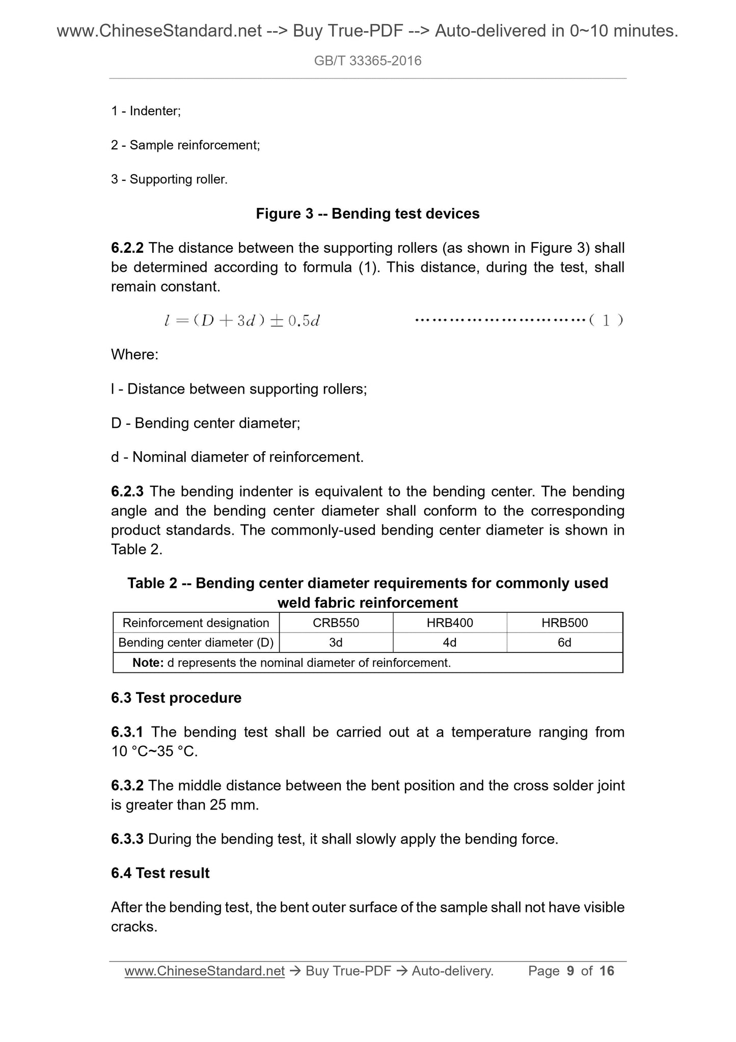
1 - Indenter;
2 - Sample reinforcement;
3 - Supporting roller.
Figure 3 -- Bending test devices
6.2.2 The distance between the supporting rollers (as shown in Figure 3) shall
be determined according to formula (1). This distance, during the test, shall
remain constant.
Where:
l - Distance between supporting rollers;
D - Bending center diameter;
d - Nominal diameter of reinforcement.
6.2.3 The bending indenter is equivalent to the bending center. The bending
angle and the bending center diameter shall conform to the corresponding
product standards. The commonly-used bending center diameter is shown in
Table 2.
Table 2 -- Bending center diameter requirements for commonly used
weld fabric reinforcement
Reinforcement designation CRB550 HRB400 HRB500
Bending center diameter (D) 3d 4d 6d
Note: d represents the nominal diameter of reinforcement.
6.3 Test procedure
6.3.1 The bending test shall be carried out at a temperature ranging from
10 °C~35 °C.
6.3.2 The middle distance between the bent position and the cross solder joint
is greater than 25 mm.
6.3.3 During the bending test, it shall slowly apply the bending force.
6.4 Test result
After the bending test, the bent outer surface of the sample shall not have visible
cracks.
7.3.2 The tensile force applied to the tensile reinforcement has a stress rate
between 6 N/mm2~60 N/mm2.
7.3.3 The arbitration test shall use the c-clamp in Appendix B.
7.3.4 The type of clamp used shall be noted in the test report.
8 Measurement of geometric characteristics
8.1 Sample
The sample shall be a complete wire fabric product of the delivery state.
8.2 Test equipment
The length, width, and grid spacing of the weld fabric sample shall be measured
using a gage with an accuracy of at least 1 mm.
8.3 Test procedure
According to the overall dimensions of a sample, MEASURE the length, width,
grid spacing, and outcrop length.
9 Measurement and calculation of weight deviation of
weld fabric
9.1 Sample
The sample shall be taken from the finished weld fabric of the delivery state.
The sample length shall not be less than the length of the tensile sample. The
sampling size shall not be less than 600 mm×600 mm. The intersection of the
mesh is not less than 9. The end of the reinforcement on the sample shall be
processed flush. The length deviation of the sample is ±1 mm.
9.2 Test equipment
The measurement accuracy of the sample weight measuring instrument shall
be at least ±0.5%. The resolution of the length measuring instrument shall be
at least 1 mm.
9.3 Result calculation
The deviation of the actual weight of weld fabric sample from the theoretical
weight shall be calculated according to formula (2):
Appendix A
(Normative)
Method for determining the total elongation of reinforcement at
maximum force
A.1 Sample
A.1.1 Length
The minimum free length between sample clamps is 350 mm.
A.1.2 Marking and measurement of original gauge length
Within the free length of the sample, it is evenly divided into equal spacing
marks of 10 mm or 5 mm. The division and measurement of marks shall comply
with the provisions of GB/T 228.1.
A.2 Tensile test
In accordance with the provisions of GB/T 228.1, CARRY out the tensile test,
until the sample fractures.
A.3 Measurement after fracture
SELECT the two marks Y and V. The distance between the two marks, before
the tensile test, shall be at least 100 mm. Both marks shall be on the side of the
clamp which is furthest from the fracture point. The distance of both marks away
from the clamp shall be no less than 20 mm. The distance between both marks
and the fracture point shall be no less than 50 mm. See Figure A.1.
The total elongation Agt (%) of the sample under maximum force may be
calculated according to formula (A.1):
Where:
L - Distance after fracture as shown in Figure A.1, in millimeters (mm);
L0 - Distance between the same marks before the test, in millimeters (mm);
Rmo - Measured value of tensile strength, in megapascals (MPa);
GB/T 33365-2016
NATIONAL STANDARD OF THE
PEOPLE’S REPUBLIC OF CHINA
ICS 77.140.60
H 44
Weld steel fabric for the reinforcement of concrete -
Test methods
(ISO 15630-2:2002, Steel for the reinforcement and prestressing of concrete -
Test methods - Part 2: Welded fabric, NEQ)
ISSUED ON: DECEMBER 30, 2016
IMPLEMENTED ON: SEPTEMBER 01, 2017
Issued by: General Administration of Quality Supervision, Inspection and
Quarantine of the PRC;
Standardization Administration of the PRC.
Table of Contents
Foreword ... 3
1 Scope ... 4
2 Normative references ... 4
3 Symbols ... 4
4 General requirements of sample ... 5
5 Tensile test ... 6
6 Bending test ... 8
7 Determination of shearing resistance ... 10
8 Measurement of geometric characteristics ... 11
9 Measurement and calculation of weight deviation of weld fabric ... 11
10 Test report ... 12
Appendix A (Normative) Method for determining the total elongation of
reinforcement at maximum force ... 13
Appendix B (Normative) Special clamps for shearing resistance test ... 15
Weld steel fabric for the reinforcement of concrete -
Test methods
1 Scope
This Standard specifies the symbols, general requirements of sample, tensile
test, bending test, determination of shearing resistance, measurement of
geometric characteristics, measurement and calculation of weight deviation,
and test report of weld steel fabric for the reinforcement of concrete (hereinafter
referred to as weld fabric).
This Standard applies to weld steel fabric for the reinforcement of concrete.
2 Normative references
The following documents are indispensable for the application of this document.
For the dated references, only the editions with the dates indicated are
applicable to this document. For the undated references, the latest edition
(including all the amendments) are applicable to this document.
GB/T 228.1 Metallic materials - Tensile testing - Part 1 : Method of test at
room temperature
GB/T 12160 Calibration of extensometers used in uniaxial testing
GB/T 16825.1 Verification of static uniaxial testing machines - Part 1:
Tension/compression testing machines - Verification and calibration of the
force-measuring system
3 Symbols
The symbols used in this Standard are shown in Table 1.
5.2 Test equipment and assistant devices
5.2.1 The testing machine shall be inspected in accordance with the provisions
of GB/T 16825.1.
5.2.2 If an extensometer is used, its accuracy level shall meet the requirements
of GB/T 12160.
5.2.3 It shall use a gage or measuring device with a resolution better than 0.1
mm to measure the final gauge length (lu), accurate to ±0.25 mm.
5.3 Test procedure
5.3.1 The test shall generally be carried out at a temperature ranging from
10 °C~35 °C.
5.3.2 For the clamping method, it shall use a suitable clamp for holding the
reinforcement to clamp the sample; it shall ensure that the clamped sample is
subjected to axial tension to minimize bending. At the same time, it shall ensure
that the sample is relatively stable during the test.
5.3.3 The test rate can be selected by the method specified in GB/T 228.1.
5.3.4 The tensile strength and yield strength are measured in accordance with
the requirements of GB/T 228.1. For reinforcement with apparently no yield
strength, the yield strength characteristic value shall be the specified non-
proportional elongation strength.
5.3.5 The percentage elongation after fracture shall be determined in
accordance with the following requirements:
a) The fractured parts of the sample shall be carefully mated together so that
their axes are on the same straight line, and the fractured parts of the
sample are in close contact before measuring.
b) It is only valid that the distance between the fracture and the closest gauge
length mark is not less than one third of the original gauge length. If the
fracture occurs at the clamping position and within 20 mm from the
clamping portion, the test is judged as invalid. However, when the
percentage elongation after fracture is greater than or equal to the
specified value, regardless of where the fracture position is, the
measurement is valid.
c) When using an extensometer to measure the fracture elongation, if the
fracture occurs within the range of the extensometer, it is valid. However,
when the percentage elongation after fracture is greater than or equal to
1 - Indenter;
2 - Sample reinforcement;
3 - Supporting roller.
Figure 3 -- Bending test devices
6.2.2 The distance between the supporting rollers (as shown in Figure 3) shall
be determined according to formula (1). This distance, during the test, shall
remain constant.
Where:
l - Distance between supporting rollers;
D - Bending center diameter;
d - Nominal diameter of reinforcement.
6.2.3 The bending indenter is equivalent to the bending center. The bending
angle and the bending center diameter shall conform to the corresponding
product standards. The commonly-used bending center diameter is shown in
Table 2.
Table 2 -- Bending center diameter requirements for commonly used
weld fabric reinforcement
Reinforcement designation CRB550 HRB400 HRB500
Bending center diameter (D) 3d 4d 6d
Note: d represents the nominal diameter of reinforcement.
6.3 Test procedure
6.3.1 The bending test shall be carried out at a temperature ranging from
10 °C~35 °C.
6.3.2 The middle distance betwee...
Delivery: 9 seconds. Download (& Email) true-PDF + Invoice.
Get Quotation: Click GB/T 33365-2016 (Self-service in 1-minute)
Historical versions (Master-website): GB/T 33365-2016
Preview True-PDF (Reload/Scroll-down if blank)
GB/T 33365-2016
NATIONAL STANDARD OF THE
PEOPLE’S REPUBLIC OF CHINA
ICS 77.140.60
H 44
Weld steel fabric for the reinforcement of concrete -
Test methods
(ISO 15630-2:2002, Steel for the reinforcement and prestressing of concrete -
Test methods - Part 2: Welded fabric, NEQ)
ISSUED ON: DECEMBER 30, 2016
IMPLEMENTED ON: SEPTEMBER 01, 2017
Issued by: General Administration of Quality Supervision, Inspection and
Quarantine of the PRC;
Standardization Administration of the PRC.
Table of Contents
Foreword ... 3
1 Scope ... 4
2 Normative references ... 4
3 Symbols ... 4
4 General requirements of sample ... 5
5 Tensile test ... 6
6 Bending test ... 8
7 Determination of shearing resistance ... 10
8 Measurement of geometric characteristics ... 11
9 Measurement and calculation of weight deviation of weld fabric ... 11
10 Test report ... 12
Appendix A (Normative) Method for determining the total elongation of
reinforcement at maximum force ... 13
Appendix B (Normative) Special clamps for shearing resistance test ... 15
Weld steel fabric for the reinforcement of concrete -
Test methods
1 Scope
This Standard specifies the symbols, general requirements of sample, tensile
test, bending test, determination of shearing resistance, measurement of
geometric characteristics, measurement and calculation of weight deviation,
and test report of weld steel fabric for the reinforcement of concrete (hereinafter
referred to as weld fabric).
This Standard applies to weld steel fabric for the reinforcement of concrete.
2 Normative references
The following documents are indispensable for the application of this document.
For the dated references, only the editions with the dates indicated are
applicable to this document. For the undated references, the latest edition
(including all the amendments) are applicable to this document.
GB/T 228.1 Metallic materials - Tensile testing - Part 1 : Method of test at
room temperature
GB/T 12160 Calibration of extensometers used in uniaxial testing
GB/T 16825.1 Verification of static uniaxial testing machines - Part 1:
Tension/compression testing machines - Verification and calibration of the
force-measuring system
3 Symbols
The symbols used in this Standard are shown in Table 1.
5.2 Test equipment and assistant devices
5.2.1 The testing machine shall be inspected in accordance with the provisions
of GB/T 16825.1.
5.2.2 If an extensometer is used, its accuracy level shall meet the requirements
of GB/T 12160.
5.2.3 It shall use a gage or measuring device with a resolution better than 0.1
mm to measure the final gauge length (lu), accurate to ±0.25 mm.
5.3 Test procedure
5.3.1 The test shall generally be carried out at a temperature ranging from
10 °C~35 °C.
5.3.2 For the clamping method, it shall use a suitable clamp for holding the
reinforcement to clamp the sample; it shall ensure that the clamped sample is
subjected to axial tension to minimize bending. At the same time, it shall ensure
that the sample is relatively stable during the test.
5.3.3 The test rate can be selected by the method specified in GB/T 228.1.
5.3.4 The tensile strength and yield strength are measured in accordance with
the requirements of GB/T 228.1. For reinforcement with apparently no yield
strength, the yield strength characteristic value shall be the specified non-
proportional elongation strength.
5.3.5 The percentage elongation after fracture shall be determined in
accordance with the following requirements:
a) The fractured parts of the sample shall be carefully mated together so that
their axes are on the same straight line, and the fractured parts of the
sample are in close contact before measuring.
b) It is only valid that the distance between the fracture and the closest gauge
length mark is not less than one third of the original gauge length. If the
fracture occurs at the clamping position and within 20 mm from the
clamping portion, the test is judged as invalid. However, when the
percentage elongation after fracture is greater than or equal to the
specified value, regardless of where the fracture position is, the
measurement is valid.
c) When using an extensometer to measure the fracture elongation, if the
fracture occurs within the range of the extensometer, it is valid. However,
when the percentage elongation after fracture is greater than or equal to
1 - Indenter;
2 - Sample reinforcement;
3 - Supporting roller.
Figure 3 -- Bending test devices
6.2.2 The distance between the supporting rollers (as shown in Figure 3) shall
be determined according to formula (1). This distance, during the test, shall
remain constant.
Where:
l - Distance between supporting rollers;
D - Bending center diameter;
d - Nominal diameter of reinforcement.
6.2.3 The bending indenter is equivalent to the bending center. The bending
angle and the bending center diameter shall conform to the corresponding
product standards. The commonly-used bending center diameter is shown in
Table 2.
Table 2 -- Bending center diameter requirements for commonly used
weld fabric reinforcement
Reinforcement designation CRB550 HRB400 HRB500
Bending center diameter (D) 3d 4d 6d
Note: d represents the nominal diameter of reinforcement.
6.3 Test procedure
6.3.1 The bending test shall be carried out at a temperature ranging from
10 °C~35 °C.
6.3.2 The middle distance between the bent position and the cross solder joint
is greater than 25 mm.
6.3.3 During the bending test, it shall slowly apply the bending force.
6.4 Test result
After the bending test, the bent outer surface of the sample shall not have visible
cracks.
7.3.2 The tensile force applied to the tensile reinforcement has a stress rate
between 6 N/mm2~60 N/mm2.
7.3.3 The arbitration test shall use the c-clamp in Appendix B.
7.3.4 The type of clamp used shall be noted in the test report.
8 Measurement of geometric characteristics
8.1 Sample
The sample shall be a complete wire fabric product of the delivery state.
8.2 Test equipment
The length, width, and grid spacing of the weld fabric sample shall be measured
using a gage with an accuracy of at least 1 mm.
8.3 Test procedure
According to the overall dimensions of a sample, MEASURE the length, width,
grid spacing, and outcrop length.
9 Measurement and calculation of weight deviation of
weld fabric
9.1 Sample
The sample shall be taken from the finished weld fabric of the delivery state.
The sample length shall not be less than the length of the tensile sample. The
sampling size shall not be less than 600 mm×600 mm. The intersection of the
mesh is not less than 9. The end of the reinforcement on the sample shall be
processed flush. The length deviation of the sample is ±1 mm.
9.2 Test equipment
The measurement accuracy of the sample weight measuring instrument shall
be at least ±0.5%. The resolution of the length measuring instrument shall be
at least 1 mm.
9.3 Result calculation
The deviation of the actual weight of weld fabric sample from the theoretical
weight shall be calculated according to formula (2):
Appendix A
(Normative)
Method for determining the total elongation of reinforcement at
maximum force
A.1 Sample
A.1.1 Length
The minimum free length between sample clamps is 350 mm.
A.1.2 Marking and measurement of original gauge length
Within the free length of the sample, it is evenly divided into equal spacing
marks of 10 mm or 5 mm. The division and measurement of marks shall comply
with the provisions of GB/T 228.1.
A.2 Tensile test
In accordance with the provisions of GB/T 228.1, CARRY out the tensile test,
until the sample fractures.
A.3 Measurement after fracture
SELECT the two marks Y and V. The distance between the two marks, before
the tensile test, shall be at least 100 mm. Both marks shall be on the side of the
clamp which is furthest from the fracture point. The distance of both marks away
from the clamp shall be no less than 20 mm. The distance between both marks
and the fracture point shall be no less than 50 mm. See Figure A.1.
The total elongation Agt (%) of the sample under maximum force may be
calculated according to formula (A.1):
Where:
L - Distance after fracture as shown in Figure A.1, in millimeters (mm);
L0 - Distance between the same marks before the test, in millimeters (mm);
Rmo - Measured value of tensile strength, in megapascals (MPa);
GB/T 33365-2016
NATIONAL STANDARD OF THE
PEOPLE’S REPUBLIC OF CHINA
ICS 77.140.60
H 44
Weld steel fabric for the reinforcement of concrete -
Test methods
(ISO 15630-2:2002, Steel for the reinforcement and prestressing of concrete -
Test methods - Part 2: Welded fabric, NEQ)
ISSUED ON: DECEMBER 30, 2016
IMPLEMENTED ON: SEPTEMBER 01, 2017
Issued by: General Administration of Quality Supervision, Inspection and
Quarantine of the PRC;
Standardization Administration of the PRC.
Table of Contents
Foreword ... 3
1 Scope ... 4
2 Normative references ... 4
3 Symbols ... 4
4 General requirements of sample ... 5
5 Tensile test ... 6
6 Bending test ... 8
7 Determination of shearing resistance ... 10
8 Measurement of geometric characteristics ... 11
9 Measurement and calculation of weight deviation of weld fabric ... 11
10 Test report ... 12
Appendix A (Normative) Method for determining the total elongation of
reinforcement at maximum force ... 13
Appendix B (Normative) Special clamps for shearing resistance test ... 15
Weld steel fabric for the reinforcement of concrete -
Test methods
1 Scope
This Standard specifies the symbols, general requirements of sample, tensile
test, bending test, determination of shearing resistance, measurement of
geometric characteristics, measurement and calculation of weight deviation,
and test report of weld steel fabric for the reinforcement of concrete (hereinafter
referred to as weld fabric).
This Standard applies to weld steel fabric for the reinforcement of concrete.
2 Normative references
The following documents are indispensable for the application of this document.
For the dated references, only the editions with the dates indicated are
applicable to this document. For the undated references, the latest edition
(including all the amendments) are applicable to this document.
GB/T 228.1 Metallic materials - Tensile testing - Part 1 : Method of test at
room temperature
GB/T 12160 Calibration of extensometers used in uniaxial testing
GB/T 16825.1 Verification of static uniaxial testing machines - Part 1:
Tension/compression testing machines - Verification and calibration of the
force-measuring system
3 Symbols
The symbols used in this Standard are shown in Table 1.
5.2 Test equipment and assistant devices
5.2.1 The testing machine shall be inspected in accordance with the provisions
of GB/T 16825.1.
5.2.2 If an extensometer is used, its accuracy level shall meet the requirements
of GB/T 12160.
5.2.3 It shall use a gage or measuring device with a resolution better than 0.1
mm to measure the final gauge length (lu), accurate to ±0.25 mm.
5.3 Test procedure
5.3.1 The test shall generally be carried out at a temperature ranging from
10 °C~35 °C.
5.3.2 For the clamping method, it shall use a suitable clamp for holding the
reinforcement to clamp the sample; it shall ensure that the clamped sample is
subjected to axial tension to minimize bending. At the same time, it shall ensure
that the sample is relatively stable during the test.
5.3.3 The test rate can be selected by the method specified in GB/T 228.1.
5.3.4 The tensile strength and yield strength are measured in accordance with
the requirements of GB/T 228.1. For reinforcement with apparently no yield
strength, the yield strength characteristic value shall be the specified non-
proportional elongation strength.
5.3.5 The percentage elongation after fracture shall be determined in
accordance with the following requirements:
a) The fractured parts of the sample shall be carefully mated together so that
their axes are on the same straight line, and the fractured parts of the
sample are in close contact before measuring.
b) It is only valid that the distance between the fracture and the closest gauge
length mark is not less than one third of the original gauge length. If the
fracture occurs at the clamping position and within 20 mm from the
clamping portion, the test is judged as invalid. However, when the
percentage elongation after fracture is greater than or equal to the
specified value, regardless of where the fracture position is, the
measurement is valid.
c) When using an extensometer to measure the fracture elongation, if the
fracture occurs within the range of the extensometer, it is valid. However,
when the percentage elongation after fracture is greater than or equal to
1 - Indenter;
2 - Sample reinforcement;
3 - Supporting roller.
Figure 3 -- Bending test devices
6.2.2 The distance between the supporting rollers (as shown in Figure 3) shall
be determined according to formula (1). This distance, during the test, shall
remain constant.
Where:
l - Distance between supporting rollers;
D - Bending center diameter;
d - Nominal diameter of reinforcement.
6.2.3 The bending indenter is equivalent to the bending center. The bending
angle and the bending center diameter shall conform to the corresponding
product standards. The commonly-used bending center diameter is shown in
Table 2.
Table 2 -- Bending center diameter requirements for commonly used
weld fabric reinforcement
Reinforcement designation CRB550 HRB400 HRB500
Bending center diameter (D) 3d 4d 6d
Note: d represents the nominal diameter of reinforcement.
6.3 Test procedure
6.3.1 The bending test shall be carried out at a temperature ranging from
10 °C~35 °C.
6.3.2 The middle distance betwee...
Share