1
/
of
12
www.ChineseStandard.us -- Field Test Asia Pte. Ltd.
GB/T 34133-2023 English PDF (GB/T34133-2023)
GB/T 34133-2023 English PDF (GB/T34133-2023)
Regular price
$800.00
Regular price
Sale price
$800.00
Unit price
/
per
Shipping calculated at checkout.
Couldn't load pickup availability
GB/T 34133-2023: Testing code for power conversion system of energy storage system
Delivery: 9 seconds. Download (& Email) true-PDF + Invoice.
Get Quotation: Click GB/T 34133-2023 (Self-service in 1-minute)
Historical versions (Master-website): GB/T 34133-2023
Preview True-PDF (Reload/Scroll-down if blank)
GB/T 34133-2023
GB
NATIONAL STANDARD OF THE
PEOPLE’S REPUBLIC OF CHINA
ICS 27.180
CCS F 19
Replacing GB/T 34133-2017
Testing Code for Power Conversion System of Energy
Storage System
ISSUED ON: DECEMBER 28, 2023
IMPLEMENTED ON: JULY 1, 2024
Issued by: State Administration for Market Regulation;
Standardization Administration of the People’s Republic of China.
Table of Contents
Foreword ... 3
1 Scope ... 6
2 Normative References ... 6
3 Terms, Definitions and Symbols ... 8
4 General Requirements ... 8
5 Detection Conditions ... 9
6 Detection Instruments and Equipment ... 9
7 Appearance Inspection and Protection Degree Detection ... 16
8 Basic Function Detection ... 17
9 Electrical Performance Detection ... 25
10 Safety Performance Detection ... 66
11 Electromagnetic Compatibility Detection ... 77
12 Auxiliary System Detection ... 80
13 Marking and Packaging Detection ... 81
Appendix A (normative) Calculation Methods for Active Power Control Response Time,
Regulation time and Control Deviation Parameters ... 83
Testing Code for Power Conversion System of Energy
Storage System
1 Scope
This document specifies the detection methods for the appearance inspection and protection
degree, basic functions, electrical performance, safety performance, electromagnetic
compatibility, auxiliary systems, marking and packaging of electrochemical energy storage
converters, as well as detection conditions, and detection instruments and equipment, etc.
This document is applicable to the design, manufacturing, testing, detection, operation,
maintenance and overhaul of energy storage converters with electrochemical cells as the energy
storage carrier, and AC port voltage of 35 kV and below.
2 Normative References
The contents of the following documents constitute indispensable clauses of this document
through the normative references in the text. In terms of references with a specified date, only
versions with a specified date are applicable to this document. In terms of references without a
specified date, the latest version (including all the modifications) is applicable to this document.
GB/T 2423.3 Environmental Testing - Part 2: Testing Method - Test Cab: Damp Heat, Steady
State
GB/T 2423.4 Environmental Testing for Electric and Electronic Products - Part 2: Test Method
- Test Db: Damp Heat, Cyclic (12 h + 12 h cycle)
GB/T 2423.18 Environmental Testing - Part 2: Test Methods - Test Kb: Salt Mist, Cyclic
(sodium chloride solution)
GB/T 2424.6 Environmental Testing for Electric and Electronic Products - Confirmation of the
Performance of Temperature / Humidity Chambers
GB/T 4208 Degrees of Protection Provided by Enclosure (IP code)
GB 4824 Industrial, Scientific and Medical Equipment - Radio-frequency Disturbance
Characteristics - Limits and Methods of Measurement
GB/T 4857.10 Packaging - Basic Tests for Transport Packages - Part 10: Sinusoidal Vibration
Test Method Using at Variable Vibration Frequency
GB/T 6092 Squares
GB/T 9286 Paints and Varnishes - Cross-cut Test
C---boost capacitor;
R---damping resistor;
S1---bypass switch;
S2---short-circuit switch.
Figure 3 -- Continuous Fault Generation Device
6.4 Battery Simulation Device
The battery simulation device shall satisfy the following requirements:
a) The output voltage deviation value is less than 0.1% of the maximum DC voltage of
the energy storage converter under test, and the adjustable step size is not greater than
0.1% of the maximum DC voltage or 0.5 V, whichever is greater;
b) The output current deviation value is less than 0.1% of the maximum DC current of
the energy storage converter under test, and the adjustable step size is not greater than
0.1% of the maximum DC current or 0.5 A, whichever is greater;
c) The voltage response time is not greater than 20 ms;
d) The dynamic voltage transient value is less than 10% of the voltage set value;
e) Electric energy can flow in both directions;
f) The rated power is not less than 1.2 times the rated power of the energy storage
converter under test;
g) The maximum output voltage is not less than 1.05 times the maximum DC voltage of
the energy storage converter under test;
h) It can simulate the charge and discharge characteristics of electrochemical batteries,
and should be able to set parameters, such as: battery type, battery nominal voltage
and battery capacity, etc.
6.5 AC Load
The AC load shall satisfy the following requirements:
a) Resistive, inductive and capacitive loads can be independently controlled;
b) The load uses non-inductive resistors, low-consumption inductors and capacitors with
low series effective internal resistance and low series effective inductance;
c) The rated power is not less than 1.2 times the rated power of the energy storage
converter under test;
d) The rated voltage is not less than the rated voltage of the energy storage converter
under test.
NOTE: AC load also uses load sources, for example, electronic load.
6.6 Temperature Detection Equipment
The temperature detection equipment shall satisfy the following requirements:
a) The data storage capacity can store all temperature data during the detection process;
b) The number of temperature measurement channels can satisfy the number of
temperature measurement points arranged;
c) The temperature measurement range of the temperature measurement channels
satisfies 40 C ~ 160 C, and the temperature measurement accuracy is not lower
than 0.5 C;
d) The time base signals of each temperature measurement channel are unified;
e) The sampling frequency is not lower than 1 Hz.
6.7 Signal Generation and Collection Device
The signal generation and collection device shall satisfy the following requirements:
a) Equipped with communication interfaces and functions, such as: CAN, RS-485 and
network port, etc.;
b) Support corresponding communication protocols, issue control signals, collect and
display communication data;
c) Equipped with CAN baud rate selection and configuration function. The baud rate
includes gear selections of 250 kbps, 500 kbps and 1,000 kbps, etc.;
d) Equipped with RS-485 serial port baud rate selection and configuration function. The
baud rate includes gear selections of 9,600 bps, 19,200 bps and 115,200 bps, etc.;
e) Equipped with network port baud rate selection and configuration function. The baud
rate includes gear selections of 100 M bps and 1 gigabit bps, etc.
6.8 Temperature / Humidity Test Chamber
The temperature / humidity test chamber shall satisfy the requirements of GB/T 2424.6
6.9 Salt Mist Detection Equipment
The salt mist detection equipment shall satisfy the requirements of GB/T 2423.18.
d) Neatness, standardization and correctness of characters and symbols.
7.2 Protection Degree
The protection degree detection is carried out in accordance with the method specified in GB/T
4208.
NOTE: when test conditions are not available, the method of providing a sample cabinet is used
for equivalent detection.
8 Basic Function Detection
8.1 Start and Stop
The start and stop detection shall be carried out in accordance with the following steps:
a) In accordance with Figure 4, connect the detection circuit, and connect switches Q1
and Q2;
b) Set the energy storage converter operating mode to discharge mode;
c) Through the signal generation and collection device, or energy storage converter
control panel, issue a command of starting to the energy storage converter;
d) After the energy storage converter is started, set the active power of the energy storage
converter to operate at the rated power. When the output power of the energy storage
converter rises to the rated power, maintain the rated power running for 2 minutes and
issue a command of stopping to the energy storage converter;
e) Utilize the data acquisition device to record the effective active power value of the
AC port of the energy storage converter from the issuance of the command of starting
to stopping with a cycle of 200 ms, and draw the active power - time curve;
f) Calculate the time from the moment when the command of starting is issued to the
moment when 90%Pn is firstly reached, and calculate the time from the moment when
the command of stopping is issued to the moment when 10%Pn is firstly reached;
g) Set the energy storage converter operating mode to charge mode and repeat steps c)
~ f).
Q1 and Q2;
b) Reverse the connection of the phase sequence of any two phases of the AC port
incoming line of the energy storage converter;
c) Connect switches Q1 and Q2 to start the energy storage converter;
d) Record the operating status and alarm information of the energy storage converter;
e) Check whether the energy storage converter has AC incoming line phase sequence
error alarm and protection functions;
f) Disconnect switches Q1 and Q2;
g) Positively connect the AC port incoming line phase sequence of the energy storage
converter;
h) Connect switches Q1 and Q2 to start the energy storage converter;
i) Record the operating status and alarm reset status of the energy storage converter;
j) Check whether the energy storage converter normally operates after the AC incoming
line phase sequence is positively connected.
8.2.3 DC voltage
8.2.3.1 DC overvoltage
The DC overvoltage alarm and protection detection shall be carried out in accordance with the
following steps:
a) In accordance with Figure 4, connect the detection circuit, and connect switches Q1
and Q2;
b) Set the energy storage converter operating mode to discharge mode;
c) Set the energy storage converter to operate at no less than 10%Pn;
d) Starting from 95% of the DC overvoltage protection set value of the energy storage
converter, take 0.5% of the maximum DC voltage as the regulation step size, adjust
the output voltage of the battery simulation device, and rise, until the DC overvoltage
protection of the energy storage converter is activated;
e) Record the DC overvoltage protection action value and alarm information of the
energy storage converter;
f) Check whether the energy storage converter has DC overvoltage alarm and protection
functions;
g) Adjust the output voltage of the battery simulation device to the normal operating DC
voltage range of the energy storage converter, and check the operating status and
alarm reset of the energy storage converter;
h) Check whether the energy storage converter normally operates when it is within the
normal operating DC voltage range;
i) Set the energy storage converter operating mode to charge mode and repeat steps c)
~ h).
8.2.3.2 DC undervoltage
DC undervoltage alarm and protection detection shall be carried out in accordance with the
following steps:
a) In accordance with Figure 4, connect the detection circuit, and connect switches Q1
and Q2;
b) Set the energy storage converter operating mode to discharge mode;
c) Set the energy storage converter to operate at no less than 10%Pn;
d) Starting from 105% of the DC undervoltage protection set value of the energy storage
converter, take 0.5% of the maximum DC voltage as the regulation step size, adjust
the output voltage of the battery simulation device, and reduce it, until the DC
undervoltage protection of the energy storage converter is activated;
e) Record the DC undervoltage protection action value and alarm information of the
energy storage converter;
f) Check whether the energy storage converter is equipped with DC undervoltage alarm
and protection functions;
g) Adjust the output voltage of the battery simulation device to the normal operating DC
voltage range of the energy storage converter, and check the operating status and
alarm reset of the energy storage converter;
h) Check whether the energy storage converter normally operates within the normal
operating DC voltage range;
i) Set the energy storage converter operating mode to charge mode and repeat steps c)
~ h).
8.2.4 Overcurrent
8.2.4.1 AC port
The AC port overcurrent alarm and protection detection shall be carried out in accordance with
h) Set the energy storage converter operating mode to charge mode and repeat steps c)
~ g).
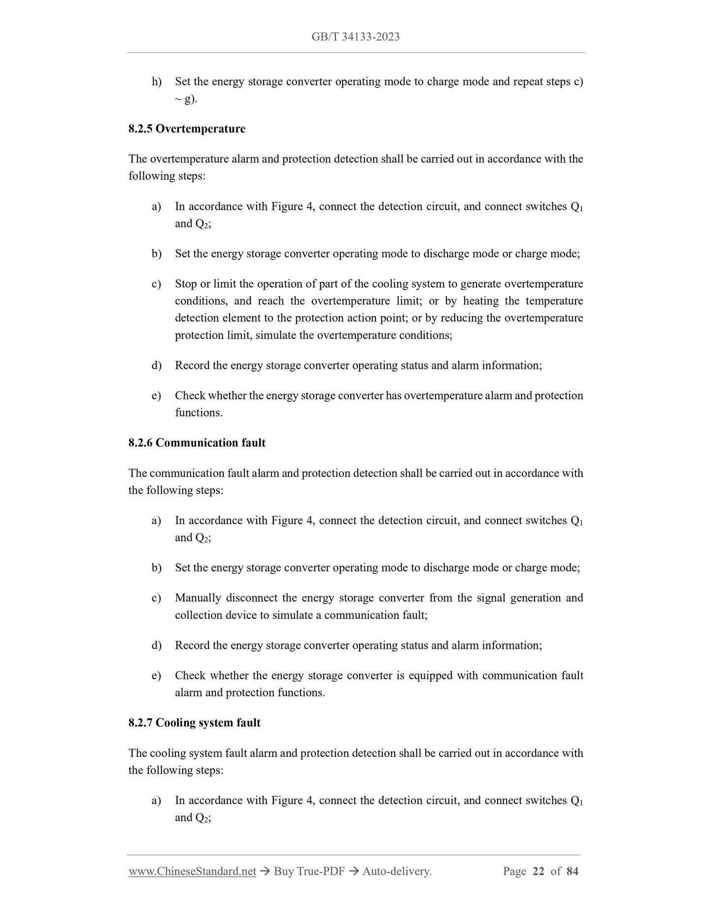
8.2.5 Overtemperature
The overtemperature alarm and protection detection shall be carried out in accordance with the
following steps:
a) In accordance with Figure 4, connect the detection circuit, and connect switches Q1
and Q2;
b) Set the energy storage converter operating mode to discharge mode or charge mode;
c) Stop or limit the operation of part of the cooling system to generate overtemperature
conditions, and reach the overtemperature limit; or by heating the temperature
detection element to the protection action point; or by reducing the overtemperature
protection limit, simulate the overtemperature conditions;
d) Record the energy storage converter operating status and alarm information;
e) Check whether the energy storage converter has overtemperature alarm and protection
functions.
8.2.6 Communication fault
The communication fault alarm and protection detection shall be carried out in accordance with
the following steps:
a) In accordance with Figure 4, connect the detection circuit, and connect switches Q1
and Q2;
b) Set the energy storage converter operating mode to discharge mode or charge mode;
c) Manually disconnect the energy storage converter from the signal generation and
collection device to simulate a communication fault;
d) Record the energy storage converter operating status and alarm information;
e) Check whether the energy storage converter is equipped with communication fault
alarm and protection functions.
8.2.7 Cooling system fault
The cooling system fault alarm and protection detection shall be carried out in accordance with
the following steps:
a) In accordance with Figure 4, connect the detection circuit, and connect switches Q1
and Q2;
b) Set the energy storage converter operating mode to discharge mode or charge mode;
c) Set the active...
Delivery: 9 seconds. Download (& Email) true-PDF + Invoice.
Get Quotation: Click GB/T 34133-2023 (Self-service in 1-minute)
Historical versions (Master-website): GB/T 34133-2023
Preview True-PDF (Reload/Scroll-down if blank)
GB/T 34133-2023
GB
NATIONAL STANDARD OF THE
PEOPLE’S REPUBLIC OF CHINA
ICS 27.180
CCS F 19
Replacing GB/T 34133-2017
Testing Code for Power Conversion System of Energy
Storage System
ISSUED ON: DECEMBER 28, 2023
IMPLEMENTED ON: JULY 1, 2024
Issued by: State Administration for Market Regulation;
Standardization Administration of the People’s Republic of China.
Table of Contents
Foreword ... 3
1 Scope ... 6
2 Normative References ... 6
3 Terms, Definitions and Symbols ... 8
4 General Requirements ... 8
5 Detection Conditions ... 9
6 Detection Instruments and Equipment ... 9
7 Appearance Inspection and Protection Degree Detection ... 16
8 Basic Function Detection ... 17
9 Electrical Performance Detection ... 25
10 Safety Performance Detection ... 66
11 Electromagnetic Compatibility Detection ... 77
12 Auxiliary System Detection ... 80
13 Marking and Packaging Detection ... 81
Appendix A (normative) Calculation Methods for Active Power Control Response Time,
Regulation time and Control Deviation Parameters ... 83
Testing Code for Power Conversion System of Energy
Storage System
1 Scope
This document specifies the detection methods for the appearance inspection and protection
degree, basic functions, electrical performance, safety performance, electromagnetic
compatibility, auxiliary systems, marking and packaging of electrochemical energy storage
converters, as well as detection conditions, and detection instruments and equipment, etc.
This document is applicable to the design, manufacturing, testing, detection, operation,
maintenance and overhaul of energy storage converters with electrochemical cells as the energy
storage carrier, and AC port voltage of 35 kV and below.
2 Normative References
The contents of the following documents constitute indispensable clauses of this document
through the normative references in the text. In terms of references with a specified date, only
versions with a specified date are applicable to this document. In terms of references without a
specified date, the latest version (including all the modifications) is applicable to this document.
GB/T 2423.3 Environmental Testing - Part 2: Testing Method - Test Cab: Damp Heat, Steady
State
GB/T 2423.4 Environmental Testing for Electric and Electronic Products - Part 2: Test Method
- Test Db: Damp Heat, Cyclic (12 h + 12 h cycle)
GB/T 2423.18 Environmental Testing - Part 2: Test Methods - Test Kb: Salt Mist, Cyclic
(sodium chloride solution)
GB/T 2424.6 Environmental Testing for Electric and Electronic Products - Confirmation of the
Performance of Temperature / Humidity Chambers
GB/T 4208 Degrees of Protection Provided by Enclosure (IP code)
GB 4824 Industrial, Scientific and Medical Equipment - Radio-frequency Disturbance
Characteristics - Limits and Methods of Measurement
GB/T 4857.10 Packaging - Basic Tests for Transport Packages - Part 10: Sinusoidal Vibration
Test Method Using at Variable Vibration Frequency
GB/T 6092 Squares
GB/T 9286 Paints and Varnishes - Cross-cut Test
C---boost capacitor;
R---damping resistor;
S1---bypass switch;
S2---short-circuit switch.
Figure 3 -- Continuous Fault Generation Device
6.4 Battery Simulation Device
The battery simulation device shall satisfy the following requirements:
a) The output voltage deviation value is less than 0.1% of the maximum DC voltage of
the energy storage converter under test, and the adjustable step size is not greater than
0.1% of the maximum DC voltage or 0.5 V, whichever is greater;
b) The output current deviation value is less than 0.1% of the maximum DC current of
the energy storage converter under test, and the adjustable step size is not greater than
0.1% of the maximum DC current or 0.5 A, whichever is greater;
c) The voltage response time is not greater than 20 ms;
d) The dynamic voltage transient value is less than 10% of the voltage set value;
e) Electric energy can flow in both directions;
f) The rated power is not less than 1.2 times the rated power of the energy storage
converter under test;
g) The maximum output voltage is not less than 1.05 times the maximum DC voltage of
the energy storage converter under test;
h) It can simulate the charge and discharge characteristics of electrochemical batteries,
and should be able to set parameters, such as: battery type, battery nominal voltage
and battery capacity, etc.
6.5 AC Load
The AC load shall satisfy the following requirements:
a) Resistive, inductive and capacitive loads can be independently controlled;
b) The load uses non-inductive resistors, low-consumption inductors and capacitors with
low series effective internal resistance and low series effective inductance;
c) The rated power is not less than 1.2 times the rated power of the energy storage
converter under test;
d) The rated voltage is not less than the rated voltage of the energy storage converter
under test.
NOTE: AC load also uses load sources, for example, electronic load.
6.6 Temperature Detection Equipment
The temperature detection equipment shall satisfy the following requirements:
a) The data storage capacity can store all temperature data during the detection process;
b) The number of temperature measurement channels can satisfy the number of
temperature measurement points arranged;
c) The temperature measurement range of the temperature measurement channels
satisfies 40 C ~ 160 C, and the temperature measurement accuracy is not lower
than 0.5 C;
d) The time base signals of each temperature measurement channel are unified;
e) The sampling frequency is not lower than 1 Hz.
6.7 Signal Generation and Collection Device
The signal generation and collection device shall satisfy the following requirements:
a) Equipped with communication interfaces and functions, such as: CAN, RS-485 and
network port, etc.;
b) Support corresponding communication protocols, issue control signals, collect and
display communication data;
c) Equipped with CAN baud rate selection and configuration function. The baud rate
includes gear selections of 250 kbps, 500 kbps and 1,000 kbps, etc.;
d) Equipped with RS-485 serial port baud rate selection and configuration function. The
baud rate includes gear selections of 9,600 bps, 19,200 bps and 115,200 bps, etc.;
e) Equipped with network port baud rate selection and configuration function. The baud
rate includes gear selections of 100 M bps and 1 gigabit bps, etc.
6.8 Temperature / Humidity Test Chamber
The temperature / humidity test chamber shall satisfy the requirements of GB/T 2424.6
6.9 Salt Mist Detection Equipment
The salt mist detection equipment shall satisfy the requirements of GB/T 2423.18.
d) Neatness, standardization and correctness of characters and symbols.
7.2 Protection Degree
The protection degree detection is carried out in accordance with the method specified in GB/T
4208.
NOTE: when test conditions are not available, the method of providing a sample cabinet is used
for equivalent detection.
8 Basic Function Detection
8.1 Start and Stop
The start and stop detection shall be carried out in accordance with the following steps:
a) In accordance with Figure 4, connect the detection circuit, and connect switches Q1
and Q2;
b) Set the energy storage converter operating mode to discharge mode;
c) Through the signal generation and collection device, or energy storage converter
control panel, issue a command of starting to the energy storage converter;
d) After the energy storage converter is started, set the active power of the energy storage
converter to operate at the rated power. When the output power of the energy storage
converter rises to the rated power, maintain the rated power running for 2 minutes and
issue a command of stopping to the energy storage converter;
e) Utilize the data acquisition device to record the effective active power value of the
AC port of the energy storage converter from the issuance of the command of starting
to stopping with a cycle of 200 ms, and draw the active power - time curve;
f) Calculate the time from the moment when the command of starting is issued to the
moment when 90%Pn is firstly reached, and calculate the time from the moment when
the command of stopping is issued to the moment when 10%Pn is firstly reached;
g) Set the energy storage converter operating mode to charge mode and repeat steps c)
~ f).
Q1 and Q2;
b) Reverse the connection of the phase sequence of any two phases of the AC port
incoming line of the energy storage converter;
c) Connect switches Q1 and Q2 to start the energy storage converter;
d) Record the operating status and alarm information of the energy storage converter;
e) Check whether the energy storage converter has AC incoming line phase sequence
error alarm and protection functions;
f) Disconnect switches Q1 and Q2;
g) Positively connect the AC port incoming line phase sequence of the energy storage
converter;
h) Connect switches Q1 and Q2 to start the energy storage converter;
i) Record the operating status and alarm reset status of the energy storage converter;
j) Check whether the energy storage converter normally operates after the AC incoming
line phase sequence is positively connected.
8.2.3 DC voltage
8.2.3.1 DC overvoltage
The DC overvoltage alarm and protection detection shall be carried out in accordance with the
following steps:
a) In accordance with Figure 4, connect the detection circuit, and connect switches Q1
and Q2;
b) Set the energy storage converter operating mode to discharge mode;
c) Set the energy storage converter to operate at no less than 10%Pn;
d) Starting from 95% of the DC overvoltage protection set value of the energy storage
converter, take 0.5% of the maximum DC voltage as the regulation step size, adjust
the output voltage of the battery simulation device, and rise, until the DC overvoltage
protection of the energy storage converter is activated;
e) Record the DC overvoltage protection action value and alarm information of the
energy storage converter;
f) Check whether the energy storage converter has DC overvoltage alarm and protection
functions;
g) Adjust the output voltage of the battery simulation device to the normal operating DC
voltage range of the energy storage converter, and check the operating status and
alarm reset of the energy storage converter;
h) Check whether the energy storage converter normally operates when it is within the
normal operating DC voltage range;
i) Set the energy storage converter operating mode to charge mode and repeat steps c)
~ h).
8.2.3.2 DC undervoltage
DC undervoltage alarm and protection detection shall be carried out in accordance with the
following steps:
a) In accordance with Figure 4, connect the detection circuit, and connect switches Q1
and Q2;
b) Set the energy storage converter operating mode to discharge mode;
c) Set the energy storage converter to operate at no less than 10%Pn;
d) Starting from 105% of the DC undervoltage protection set value of the energy storage
converter, take 0.5% of the maximum DC voltage as the regulation step size, adjust
the output voltage of the battery simulation device, and reduce it, until the DC
undervoltage protection of the energy storage converter is activated;
e) Record the DC undervoltage protection action value and alarm information of the
energy storage converter;
f) Check whether the energy storage converter is equipped with DC undervoltage alarm
and protection functions;
g) Adjust the output voltage of the battery simulation device to the normal operating DC
voltage range of the energy storage converter, and check the operating status and
alarm reset of the energy storage converter;
h) Check whether the energy storage converter normally operates within the normal
operating DC voltage range;
i) Set the energy storage converter operating mode to charge mode and repeat steps c)
~ h).
8.2.4 Overcurrent
8.2.4.1 AC port
The AC port overcurrent alarm and protection detection shall be carried out in accordance with
h) Set the energy storage converter operating mode to charge mode and repeat steps c)
~ g).
8.2.5 Overtemperature
The overtemperature alarm and protection detection shall be carried out in accordance with the
following steps:
a) In accordance with Figure 4, connect the detection circuit, and connect switches Q1
and Q2;
b) Set the energy storage converter operating mode to discharge mode or charge mode;
c) Stop or limit the operation of part of the cooling system to generate overtemperature
conditions, and reach the overtemperature limit; or by heating the temperature
detection element to the protection action point; or by reducing the overtemperature
protection limit, simulate the overtemperature conditions;
d) Record the energy storage converter operating status and alarm information;
e) Check whether the energy storage converter has overtemperature alarm and protection
functions.
8.2.6 Communication fault
The communication fault alarm and protection detection shall be carried out in accordance with
the following steps:
a) In accordance with Figure 4, connect the detection circuit, and connect switches Q1
and Q2;
b) Set the energy storage converter operating mode to discharge mode or charge mode;
c) Manually disconnect the energy storage converter from the signal generation and
collection device to simulate a communication fault;
d) Record the energy storage converter operating status and alarm information;
e) Check whether the energy storage converter is equipped with communication fault
alarm and protection functions.
8.2.7 Cooling system fault
The cooling system fault alarm and protection detection shall be carried out in accordance with
the following steps:
a) In accordance with Figure 4, connect the detection circuit, and connect switches Q1
and Q2;
b) Set the energy storage converter operating mode to discharge mode or charge mode;
c) Set the active...
Share