1
/
of
8
www.ChineseStandard.us -- Field Test Asia Pte. Ltd.
GB/T 36048-2018 English PDF (GB/T36048-2018)
GB/T 36048-2018 English PDF (GB/T36048-2018)
Regular price
$150.00
Regular price
Sale price
$150.00
Unit price
/
per
Shipping calculated at checkout.
Couldn't load pickup availability
GB/T 36048-2018: Passenger Cars Physical Layer Technical Specification of CAN Bus
Delivery: 9 seconds. Download (& Email) true-PDF + Invoice.
Get Quotation: Click GB/T 36048-2018 (Self-service in 1-minute)
Historical versions (Master-website): GB/T 36048-2018
Preview True-PDF (Reload/Scroll-down if blank)
GB/T 36048-2018
GB
NATIONAL STANDARD OF THE
PEOPLE’S REPUBLIC OF CHINA
ICS 43.040.40
T 24
Passenger Cars Physical Layer
Technical Specification of CAN Bus
ISSUED ON. MARCH 15, 2018
IMPLEMENTED ON. OCTOBER 01, 2018
Issued by. General Administration of Quality Supervision, Inspection and
Quarantine;
Standardization Administration of PRC.
Table of Contents
Foreword ... 3
1 Scope ... 4
2 Terms and Definitions ... 4
3 General Requirements of Physical Layer ... 7
4 Physical Layer Signaling ... 8
5 High-Speed Media Access Unit ... 14
6 High-Speed Media Access Unit with Low Power Mode... 21
7 High-Speed Media Access Unit with Selective Wake-up Function ... 25
8 Bus Failure Management ... 27
Passenger Cars Physical Layer
Technical Specification of CAN Bus
1 Scope
This Standard specifies the terms and definitions of the physical layer of the high-
speed CAN bus, the general requirements of the physical layer, technical requirements
of physical layer signaling, high-speed media access unit, and bus failure management.
This Standard is applicable to high-speed CAN buses with communication rate from
125Kbit/s to 1Mbit/s.
2 Terms and Definitions
The following terms and definitions are applicable to this document.
2.1 Controller area network; CAN
A network communication technology for road vehicles.
2.2 Bus
A network communication topology that all nodes access to the network through a two-
way transmission mode.
2.3 Bus state
One of two opposite logical states. explicit or implicit.
2.4 Physical layer
The electrical circuit (bus comparator and bus driver) that connects the CAN nodes to
the bus; it consists of three parts, namely, analog circuit, digital circuit and analog signal
on the CAN bus, and digital signal interface circuit inside the CAN node.
NOTE. The maximum number of nodes allowed to connect on the CAN bus depends on the
electrical load of the CAN bus.
2.5 Physical media (of the bus)
A pair of shielded or unshielded twisted pair cables for signal transmission.
Differential voltage of CAN bus, Vdiff = VCAN_H - VCAN_L.
2.16 Internal capacitance (of a CAN node), Cin
The capacitance measured under CAN_L (or CAN_H) in the implicit state, when the
CAN node is disconnected from the bus.
2.17 Internal delay time (of a CAN node), Tnode
The sum of all asynchronous delays that occur during the transmission or reception; it
is related to the bit time logic unit of each node integrated circuit.
2.18 Internal resistance (of a CAN node), Rin
The resistance measured under CAN_L (or CAN_H) in the implicit state, when the CAN
node is disconnected from the bus.
2.19 Supply voltage, Vcc
The voltage supplied to the bus transmitter, receiver, and optional split termination in
the normal operating mode.
2.20 Split termination voltage, VSplit
The output voltage of split termination of CAN node relative to the signal ground of the
module.
2.21 Propagation time, tProp
The time from a transmission data input edge of the medial access unit to a
corresponding reception data output edge.
2.22 Wake-up frame
A CAN data frame used to wake-up one or more CAN nodes.
2.23 Wake-up filter time, twake
The explicit signal duration that can force the CAN node to wake up on the buses of
CAN_H and CAN_L.
2.24 Activity filter time, tFilter
The duration of the explicit and implicit levels on the buses of CAN_H and CAN_L,
which is used to monitor whether the activity on the CAN bus is effective.
2.25 Transceiver
The physical layer shall provide services for exchanging data bits between two peer
media to access control sublayers; which include physical layer signaling data
requests and physical layer signaling data indications.
The physical layer signaling data request service is sent from media access control
sublayer to the physical layer, requesting the transmission of an explicit or implicit bit.
The physical layer signaling data indication service is sent from physical layer to the
media access sublayer, indicating the arrival of an explicit or implicit bit.
3.3 Interface between physical layer signaling and physical media attachment
3.3.1 Message from physical layer signaling to the physical media attachment
When the physical layer signaling receives a signal from the physical medial
accessories, the physical layer signaling shall sent an explicit or implicit output
message to the physical media attachment.
When physical layer signaling receives a bus close request, the physical layer
signaling shall send a bus close message to the physical media attachment.
When physical layer signaling receives the bus close and release request, the physical
layer signaling shall send a bus close and release message to the physical media
attachment.
3.3.2 Message from physical media attachment to physical layer signaling
When the media access unit receives a bit from the media; the physical media
attachment shall send an input message to the physical layer signaling. Such input
message represents the arrival of an explicit or implicit bit to the physical layer
signaling.
4 Physical Layer Signaling
4.1 Bit encoding and decoding
4.1.1 Bit time
The bus management functions realized within one-bit time, including CAN node
synchronization, network transmission delay compensation, sampling point positioning,
all of which shall be performed in accordance with programmable bit timing logic; such
logic is given by the CAN integrated circuit.
The nominal bit time is divided into 4 non-overlapping time segments, as shown in
Figure 2.
a) Only one synchronization (between two sampling points) is allowed in one bit
time.
b) Only when testing the bus state of the previous sampling point is different from
the bus state behind the sampling point edge, the implicit to explicit trip edge can
be used for synchronization.
c) When the implicit to explicit trip edge occurs during the frame interval, the hard
synchronization shall be performed (except for the first bit interval).
d) All other implicit to explicit trip edge that satisfy the rules of a) and b) shall be
applied to resynchronization. Except for the following cases, when the implicit to
explicit trip edge has a positive phase error, the node sending explicit bit shall
not perform resynchronization.
4.2.2 Phase error of synchronization edge
The phase error of synchronization edge, e, is related to the synchronization segment;
which is measured with time slice as the unit. The sign definition of phase error is as
follows.
a) When the trip edge falls within the synchronization segment, e = 0;
b) When the trip edge falls before the sampling point, e > 0;
c) When the trip edge falls behind the sampling point, e < 0.
4.2.3 Hard synchronization
After hard synchronization, the bit timing logic unit shall restart the bit time from the
synchronization segment. Therefore, the hard synchronization shall force the trip edge
that caused the hard synchronization to be within the synchronization segment that
starts to restart the bit time.
4.2.4 Resynchronization
When the phase error amplitude of the trip edge that causes the resynchronization is
less than or equal to the setting value of the resynchronization jump width, the
resynchronization shall lengthen or shorten the bit time to ensure the correct sampling
point position. When the phase error amplitude is greater than the resynchronization
jump width.
--- If the phaser error, e, is positive, then phase buffer segment 1 shall be increased
the value equal to the resynchronization jump width;
--- If the phaser error, e, is negative, then the phase buffer segment 2 shall be
shortened the value equal to the resynchronization jump width.
6.1.3 Wake-up to exit the low power mode
When it is in the low power mode, physical layer shall monitor the CAN_H and CAN_L
of the CAN bus for wakeup. When the bus appears one or more consecutive explicate
bus level that can last for at least twake time; and when separated by an implicate bus
level, then the bus wakeup shall be performed.
6.1.4 Power-off node system
In order not to affect the CAN communication system, for the actively powered off node
(e.g.. ignition key control module), the power-off node shall not affect the bus level as
much as possible, when other nodes remain the normal communication. The
transceiver shall produce the lowest leakage current to the bus that is still
communicating.
Based on the application objectives, the node that is continuously powered shall allow
the maximum leakage current parameter defined in Table 13; and the node that is
temporarily unpowered shall minimize the leakage current as much as possible.
6.2 Electrical technical requirements
6.2.1 Physical media attachment
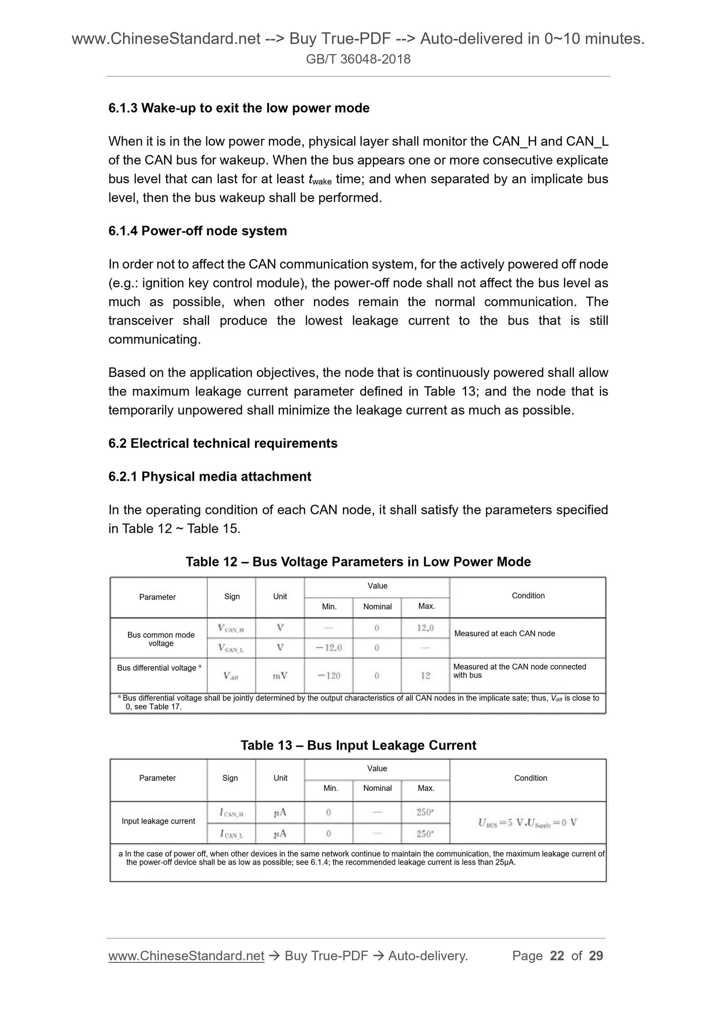
In the operating condition of each CAN node, it shall satisfy the parameters specified
in Table 12 ~ Table 15.
Table 12 – Bus Voltage Parameters in Low Power Mode
Table 13 – Bus Input Leakage Current
Parameter Sign Unit
Value
Min. Nominal Max.
Condition
Bus common mode
voltage
Bus differential voltage a Measured at the CAN node connected with bus
Measured at each CAN node
a Bus differential voltage shall be jointly determined by the output characteristics of all CAN nodes in the implicate sate; thus, Vdiff is close to
0, see Table 17.
Parameter Sign Unit
Value
Min. Nominal Max.
Condition
Input leakage current
a In the case of power off, when other devices in the same network continue to maintain the communication, the maximum leakage current of
the power-off device shall be as low as possible; see 6.1.4; the recommended leakage current is less than 25µA.
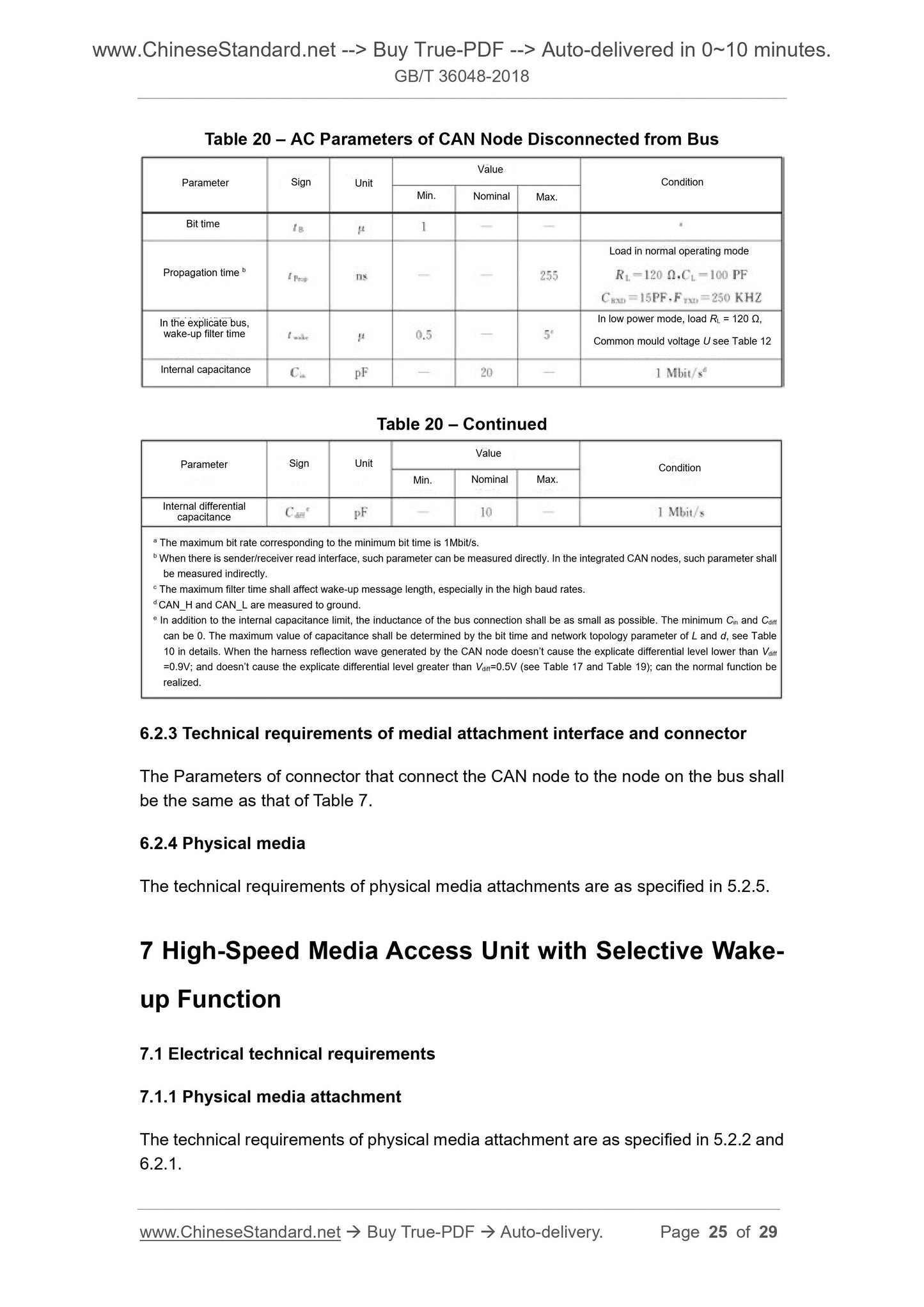
Table 20 – AC Parameters of CAN Node Disconnected from Bus
Table 20 – Continued
6.2.3 Technical requirements of medial attachment interface and connector
The Parameters of connector that connect the CAN node to the node on the bus shall
be the same as that of Table 7.
6.2.4 Physical media
The technical requirements of physical media attachments are as specified in 5.2.5.
7 High-Speed Media Access Unit with Selective Wake-
up Function
7.1 Electrical technical requirements
7.1.1 Physical media attachment
The technical requirements of physical media attachment are as specified in 5.2.2 and
6.2.1.
Bit time
Parameter Sign Unit
Value
Min. Nominal Max.
Condition
Propagation time b
In the explicate bus,
wake-up filter time
Internal capacitance
Load in normal operating mode
In low power mode, load RL = 120 Ω,
Common mould voltage U see Table 12
Parameter Sign Unit
Value
Min. Nominal Max.
Condition
Internal differential
capacitance
a The maximum bit rate corresponding to the minimum bit time is 1Mbit/s.
b When there is sender/receiver read interface, such parameter can be measured directly. In the integrated CAN nodes, such parameter shall
be measured indirectly.
c The maximum filter time shall affect wake-up message length, especially in the high baud rates.
d CAN_H and CAN_L are measured to ground.
e In addition to the internal capacitance limit, the inductance of the bus connection shall be as small as possible. The minimum Cin and Cdiff
can be 0. The maximum value of capacitance shall be determined by the bit time and network topology parameter of L and d, see Table
10 in details. When the harness reflection wave generated by the CAN node doesn’t cause the explicate differential level lower than Vdiff
=0.9V; and doesn’t cause the explicate differential level greater than Vdiff=0.5V (see Table 17 and Table 19); can the normal function be
realized.
GB/T 36048-2018
GB
NATIONAL STANDARD OF THE
PEOPLE’S REPUBLIC OF CHINA
ICS 43.040.40
T 24
Passenger Cars Physical Layer
Technical Specification of CAN Bus
ISSUED ON. MARCH 15, 2018
IMPLEMENTED ON. OCTOBER 01, 2018
Issued by. General Administration of Quality Supervision, Inspection and
Quarantine;
Standardization Administration of PRC.
Table of Contents
Foreword ... 3
1 Scope ... 4
2 Terms and Definitions ... 4
3 General Requirements of Physical Layer ... 7
4 Physical Layer Signaling ... 8
5 High-Speed Media Access Unit ... 14
6 High-Speed Media Access Unit with Low Power Mode... 21
7 High-Speed Media Access Unit with Selective Wake-up Function ... 25
8 Bus Failure Management ... 27
Passenger Cars Physical Layer
Technical Specification of CAN Bus
1 Scope
This Standard specifies the terms and definitions of the physical layer of the high-
speed CAN bus, the general requirements of the physical layer, technical requirements
of physical layer signaling, high-speed media access unit, and bus failure management.
This Standard is applicable to high-speed CAN buses with communication rate from
125Kbit/s to 1Mbit/s.
2 Terms and Definitions
The following terms and definitions are applicable to this document.
2.1 Controller area network; CAN
A network communication technology for road vehicles.
2.2 Bus
A network communication topology that all nodes access to the network through a two-
way transmission mode.
2.3 Bus state
One of two opposite logical states. explicit or implicit.
2.4 Physical layer
The electrical circuit (bus comparator and bus driver) that connects the CAN nodes to
the bus; it consists of three parts, namely, analog circuit, digital circuit and analog signal
on the CAN bus, and digital signal interface circuit inside the CAN node.
NOTE. The maximum number of nodes allowed to connect on the CAN bus depends on the
electrical load of the CAN bus.
2.5 Physical media (of the bus)
A pair of shielded or unshielded twisted pair cables for signal transmission.
Differential voltage of CAN bus, Vdiff = VCAN_H - VCAN_L.
2.16 Internal capacitance (of a CAN node), Cin
The capacitance measured under CAN_L (or CAN_H) in the implicit state, when the
CAN node is disconnected from the bus.
2.17 Internal delay time (of a CAN node), Tnode
The sum of all a...
Delivery: 9 seconds. Download (& Email) true-PDF + Invoice.
Get Quotation: Click GB/T 36048-2018 (Self-service in 1-minute)
Historical versions (Master-website): GB/T 36048-2018
Preview True-PDF (Reload/Scroll-down if blank)
GB/T 36048-2018
GB
NATIONAL STANDARD OF THE
PEOPLE’S REPUBLIC OF CHINA
ICS 43.040.40
T 24
Passenger Cars Physical Layer
Technical Specification of CAN Bus
ISSUED ON. MARCH 15, 2018
IMPLEMENTED ON. OCTOBER 01, 2018
Issued by. General Administration of Quality Supervision, Inspection and
Quarantine;
Standardization Administration of PRC.
Table of Contents
Foreword ... 3
1 Scope ... 4
2 Terms and Definitions ... 4
3 General Requirements of Physical Layer ... 7
4 Physical Layer Signaling ... 8
5 High-Speed Media Access Unit ... 14
6 High-Speed Media Access Unit with Low Power Mode... 21
7 High-Speed Media Access Unit with Selective Wake-up Function ... 25
8 Bus Failure Management ... 27
Passenger Cars Physical Layer
Technical Specification of CAN Bus
1 Scope
This Standard specifies the terms and definitions of the physical layer of the high-
speed CAN bus, the general requirements of the physical layer, technical requirements
of physical layer signaling, high-speed media access unit, and bus failure management.
This Standard is applicable to high-speed CAN buses with communication rate from
125Kbit/s to 1Mbit/s.
2 Terms and Definitions
The following terms and definitions are applicable to this document.
2.1 Controller area network; CAN
A network communication technology for road vehicles.
2.2 Bus
A network communication topology that all nodes access to the network through a two-
way transmission mode.
2.3 Bus state
One of two opposite logical states. explicit or implicit.
2.4 Physical layer
The electrical circuit (bus comparator and bus driver) that connects the CAN nodes to
the bus; it consists of three parts, namely, analog circuit, digital circuit and analog signal
on the CAN bus, and digital signal interface circuit inside the CAN node.
NOTE. The maximum number of nodes allowed to connect on the CAN bus depends on the
electrical load of the CAN bus.
2.5 Physical media (of the bus)
A pair of shielded or unshielded twisted pair cables for signal transmission.
Differential voltage of CAN bus, Vdiff = VCAN_H - VCAN_L.
2.16 Internal capacitance (of a CAN node), Cin
The capacitance measured under CAN_L (or CAN_H) in the implicit state, when the
CAN node is disconnected from the bus.
2.17 Internal delay time (of a CAN node), Tnode
The sum of all asynchronous delays that occur during the transmission or reception; it
is related to the bit time logic unit of each node integrated circuit.
2.18 Internal resistance (of a CAN node), Rin
The resistance measured under CAN_L (or CAN_H) in the implicit state, when the CAN
node is disconnected from the bus.
2.19 Supply voltage, Vcc
The voltage supplied to the bus transmitter, receiver, and optional split termination in
the normal operating mode.
2.20 Split termination voltage, VSplit
The output voltage of split termination of CAN node relative to the signal ground of the
module.
2.21 Propagation time, tProp
The time from a transmission data input edge of the medial access unit to a
corresponding reception data output edge.
2.22 Wake-up frame
A CAN data frame used to wake-up one or more CAN nodes.
2.23 Wake-up filter time, twake
The explicit signal duration that can force the CAN node to wake up on the buses of
CAN_H and CAN_L.
2.24 Activity filter time, tFilter
The duration of the explicit and implicit levels on the buses of CAN_H and CAN_L,
which is used to monitor whether the activity on the CAN bus is effective.
2.25 Transceiver
The physical layer shall provide services for exchanging data bits between two peer
media to access control sublayers; which include physical layer signaling data
requests and physical layer signaling data indications.
The physical layer signaling data request service is sent from media access control
sublayer to the physical layer, requesting the transmission of an explicit or implicit bit.
The physical layer signaling data indication service is sent from physical layer to the
media access sublayer, indicating the arrival of an explicit or implicit bit.
3.3 Interface between physical layer signaling and physical media attachment
3.3.1 Message from physical layer signaling to the physical media attachment
When the physical layer signaling receives a signal from the physical medial
accessories, the physical layer signaling shall sent an explicit or implicit output
message to the physical media attachment.
When physical layer signaling receives a bus close request, the physical layer
signaling shall send a bus close message to the physical media attachment.
When physical layer signaling receives the bus close and release request, the physical
layer signaling shall send a bus close and release message to the physical media
attachment.
3.3.2 Message from physical media attachment to physical layer signaling
When the media access unit receives a bit from the media; the physical media
attachment shall send an input message to the physical layer signaling. Such input
message represents the arrival of an explicit or implicit bit to the physical layer
signaling.
4 Physical Layer Signaling
4.1 Bit encoding and decoding
4.1.1 Bit time
The bus management functions realized within one-bit time, including CAN node
synchronization, network transmission delay compensation, sampling point positioning,
all of which shall be performed in accordance with programmable bit timing logic; such
logic is given by the CAN integrated circuit.
The nominal bit time is divided into 4 non-overlapping time segments, as shown in
Figure 2.
a) Only one synchronization (between two sampling points) is allowed in one bit
time.
b) Only when testing the bus state of the previous sampling point is different from
the bus state behind the sampling point edge, the implicit to explicit trip edge can
be used for synchronization.
c) When the implicit to explicit trip edge occurs during the frame interval, the hard
synchronization shall be performed (except for the first bit interval).
d) All other implicit to explicit trip edge that satisfy the rules of a) and b) shall be
applied to resynchronization. Except for the following cases, when the implicit to
explicit trip edge has a positive phase error, the node sending explicit bit shall
not perform resynchronization.
4.2.2 Phase error of synchronization edge
The phase error of synchronization edge, e, is related to the synchronization segment;
which is measured with time slice as the unit. The sign definition of phase error is as
follows.
a) When the trip edge falls within the synchronization segment, e = 0;
b) When the trip edge falls before the sampling point, e > 0;
c) When the trip edge falls behind the sampling point, e < 0.
4.2.3 Hard synchronization
After hard synchronization, the bit timing logic unit shall restart the bit time from the
synchronization segment. Therefore, the hard synchronization shall force the trip edge
that caused the hard synchronization to be within the synchronization segment that
starts to restart the bit time.
4.2.4 Resynchronization
When the phase error amplitude of the trip edge that causes the resynchronization is
less than or equal to the setting value of the resynchronization jump width, the
resynchronization shall lengthen or shorten the bit time to ensure the correct sampling
point position. When the phase error amplitude is greater than the resynchronization
jump width.
--- If the phaser error, e, is positive, then phase buffer segment 1 shall be increased
the value equal to the resynchronization jump width;
--- If the phaser error, e, is negative, then the phase buffer segment 2 shall be
shortened the value equal to the resynchronization jump width.
6.1.3 Wake-up to exit the low power mode
When it is in the low power mode, physical layer shall monitor the CAN_H and CAN_L
of the CAN bus for wakeup. When the bus appears one or more consecutive explicate
bus level that can last for at least twake time; and when separated by an implicate bus
level, then the bus wakeup shall be performed.
6.1.4 Power-off node system
In order not to affect the CAN communication system, for the actively powered off node
(e.g.. ignition key control module), the power-off node shall not affect the bus level as
much as possible, when other nodes remain the normal communication. The
transceiver shall produce the lowest leakage current to the bus that is still
communicating.
Based on the application objectives, the node that is continuously powered shall allow
the maximum leakage current parameter defined in Table 13; and the node that is
temporarily unpowered shall minimize the leakage current as much as possible.
6.2 Electrical technical requirements
6.2.1 Physical media attachment
In the operating condition of each CAN node, it shall satisfy the parameters specified
in Table 12 ~ Table 15.
Table 12 – Bus Voltage Parameters in Low Power Mode
Table 13 – Bus Input Leakage Current
Parameter Sign Unit
Value
Min. Nominal Max.
Condition
Bus common mode
voltage
Bus differential voltage a Measured at the CAN node connected with bus
Measured at each CAN node
a Bus differential voltage shall be jointly determined by the output characteristics of all CAN nodes in the implicate sate; thus, Vdiff is close to
0, see Table 17.
Parameter Sign Unit
Value
Min. Nominal Max.
Condition
Input leakage current
a In the case of power off, when other devices in the same network continue to maintain the communication, the maximum leakage current of
the power-off device shall be as low as possible; see 6.1.4; the recommended leakage current is less than 25µA.
Table 20 – AC Parameters of CAN Node Disconnected from Bus
Table 20 – Continued
6.2.3 Technical requirements of medial attachment interface and connector
The Parameters of connector that connect the CAN node to the node on the bus shall
be the same as that of Table 7.
6.2.4 Physical media
The technical requirements of physical media attachments are as specified in 5.2.5.
7 High-Speed Media Access Unit with Selective Wake-
up Function
7.1 Electrical technical requirements
7.1.1 Physical media attachment
The technical requirements of physical media attachment are as specified in 5.2.2 and
6.2.1.
Bit time
Parameter Sign Unit
Value
Min. Nominal Max.
Condition
Propagation time b
In the explicate bus,
wake-up filter time
Internal capacitance
Load in normal operating mode
In low power mode, load RL = 120 Ω,
Common mould voltage U see Table 12
Parameter Sign Unit
Value
Min. Nominal Max.
Condition
Internal differential
capacitance
a The maximum bit rate corresponding to the minimum bit time is 1Mbit/s.
b When there is sender/receiver read interface, such parameter can be measured directly. In the integrated CAN nodes, such parameter shall
be measured indirectly.
c The maximum filter time shall affect wake-up message length, especially in the high baud rates.
d CAN_H and CAN_L are measured to ground.
e In addition to the internal capacitance limit, the inductance of the bus connection shall be as small as possible. The minimum Cin and Cdiff
can be 0. The maximum value of capacitance shall be determined by the bit time and network topology parameter of L and d, see Table
10 in details. When the harness reflection wave generated by the CAN node doesn’t cause the explicate differential level lower than Vdiff
=0.9V; and doesn’t cause the explicate differential level greater than Vdiff=0.5V (see Table 17 and Table 19); can the normal function be
realized.
GB/T 36048-2018
GB
NATIONAL STANDARD OF THE
PEOPLE’S REPUBLIC OF CHINA
ICS 43.040.40
T 24
Passenger Cars Physical Layer
Technical Specification of CAN Bus
ISSUED ON. MARCH 15, 2018
IMPLEMENTED ON. OCTOBER 01, 2018
Issued by. General Administration of Quality Supervision, Inspection and
Quarantine;
Standardization Administration of PRC.
Table of Contents
Foreword ... 3
1 Scope ... 4
2 Terms and Definitions ... 4
3 General Requirements of Physical Layer ... 7
4 Physical Layer Signaling ... 8
5 High-Speed Media Access Unit ... 14
6 High-Speed Media Access Unit with Low Power Mode... 21
7 High-Speed Media Access Unit with Selective Wake-up Function ... 25
8 Bus Failure Management ... 27
Passenger Cars Physical Layer
Technical Specification of CAN Bus
1 Scope
This Standard specifies the terms and definitions of the physical layer of the high-
speed CAN bus, the general requirements of the physical layer, technical requirements
of physical layer signaling, high-speed media access unit, and bus failure management.
This Standard is applicable to high-speed CAN buses with communication rate from
125Kbit/s to 1Mbit/s.
2 Terms and Definitions
The following terms and definitions are applicable to this document.
2.1 Controller area network; CAN
A network communication technology for road vehicles.
2.2 Bus
A network communication topology that all nodes access to the network through a two-
way transmission mode.
2.3 Bus state
One of two opposite logical states. explicit or implicit.
2.4 Physical layer
The electrical circuit (bus comparator and bus driver) that connects the CAN nodes to
the bus; it consists of three parts, namely, analog circuit, digital circuit and analog signal
on the CAN bus, and digital signal interface circuit inside the CAN node.
NOTE. The maximum number of nodes allowed to connect on the CAN bus depends on the
electrical load of the CAN bus.
2.5 Physical media (of the bus)
A pair of shielded or unshielded twisted pair cables for signal transmission.
Differential voltage of CAN bus, Vdiff = VCAN_H - VCAN_L.
2.16 Internal capacitance (of a CAN node), Cin
The capacitance measured under CAN_L (or CAN_H) in the implicit state, when the
CAN node is disconnected from the bus.
2.17 Internal delay time (of a CAN node), Tnode
The sum of all a...
Share