1
/
of
4
PayPal, credit cards. Download editable-PDF and invoice in 1 second!
GB/T 36607-2018 English PDF (GBT36607-2018)
GB/T 36607-2018 English PDF (GBT36607-2018)
Regular price
$150.00 USD
Regular price
Sale price
$150.00 USD
Unit price
/
per
Shipping calculated at checkout.
Couldn't load pickup availability
Delivery: 3 seconds. Download true-PDF + Invoice.
Get QUOTATION in 1-minute: Click GB/T 36607-2018
Historical versions: GB/T 36607-2018
Preview True-PDF (Reload/Scroll if blank)
GB/T 36607-2018: Ergonomics -- Motor vehicle driver head position
GB/T 36607-2018
NATIONAL STANDARD OF THE
PEOPLE’S REPUBLIC OF CHINA
ICS 13.180
A 25
Ergonomics - Motor Vehicle Driver Head Position
ISSUED ON: SEPTEMBER 17, 2018
IMPLEMENTED ON: JANUARY 1, 2019
Issued by: State Administration for Market Regulation;
Standardization Administration of the People’s Republic of
China.
Table of Contents
Foreword ... 3
1 Scope ... 4
2 Normative References ... 4
3 Terms and Definitions ... 4
4 Overview ... 5
5 Drivers’ Head Position Contour Geometry ... 5
Bibliography ... 9
Ergonomics - Motor Vehicle Driver Head Position
1 Scope
This Standard provides Chinese motor vehicle drivers’ head position, including the
principle of drivers’ head position contour geometry formation; axis length of head
position contour geometry whose vehicle seat stroke is more than 133 mm, and
inclination angle and central location in the lateral view.
This Standard is applicable to vehicle body space design for Class M1 motor vehicles
whose seat stroke is more than 133 mm.
2 Normative References
The following documents are indispensable to the application of this Standard. In terms
of references with a specified date, only versions with a specified date are applicable
to this Standard. In terms of references without a specified date, the latest version
(including all the modifications) is applicable to this Standard.
GB/T 15089-2001 Classification of Power-driven Vehicles and Trailers
3 Terms and Definitions
Terms and definitions defined in GB/T 15089-2001, and the following terms and
definitions are applicable to this Standard.
3.1 Eyellipse
Eyellipse refers to the statistical representation of drivers’ eyes in spatially relative
internal vehicle reference point locations.
3.2 Head Position Contour Geometry
Head position contour geometry refers to the geometry of head contour (including hair)
when passengers of different statures are sitting in a reasonable position in normal
posture.
3.3 Class M1 Vehicles
Class Mi vehicles refers to passenger-carrying vehicles whose number of seats
(including the driver’s seat) does not exceed nine.
[GB/T 15089-2001, Definition 3.2]
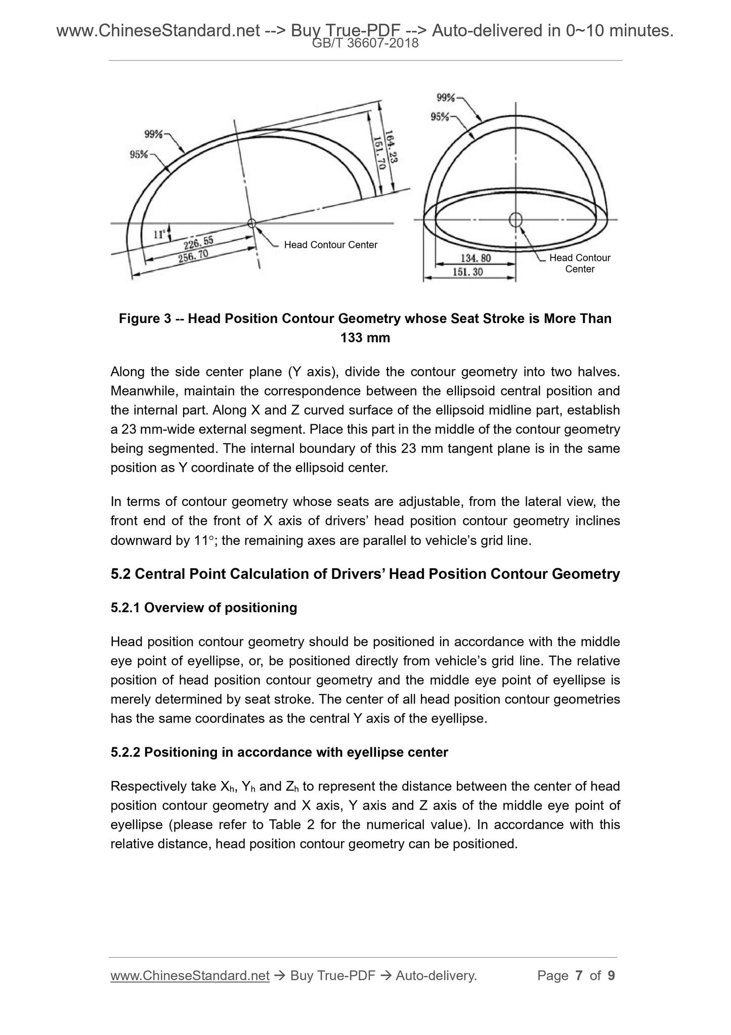
Figure 3 -- Head Position Contour Geometry whose Seat Stroke is More Than
133 mm
Along the side center plane (Y axis), divide the contour geometry into two halves.
Meanwhile, maintain the correspondence between the ellipsoid central position and
the internal part. Along X and Z curved surface of the ellipsoid midline part, establish
a 23 mm-wide external segment. Place this part in the middle of the contour geometry
being segmented. The internal boundary of this 23 mm tangent plane is in the same
position as Y coordinate of the ellipsoid center.
In terms of contour geometry whose seats are adjustable, from the lateral view, the
front end of the front of X axis of drivers’ head position contour geometry inclines
downward by 11; the remaining axes are parallel to vehicle’s grid line.
5.2 Central Point Calculation of Drivers’ Head Position Contour Geometry
5.2.1 Overview of positioning
Head position contour geometry should be positioned in accordance with the middle
eye point of eyellipse, or, be positioned directly from vehicle’s grid line. The relative
position of head position contour geometry and the middle eye point of eyellipse is
merely determined by seat stroke. The center of all head position contour geometries
has the same coordinates as the central Y axis of the eyellipse.
5.2.2 Positioning in accordance with eyellipse center
Respectively take Xh, Yh and Zh to represent the distance between the center of head
position contour geometry and X axis, Y axis and Z axis of the middle eye point of
eyellipse (please refer to Table 2 for the numerical value). In accordance with this
relative distance, head position contour geometry can be positioned.
Head Contour Center
Head Contour
Center
Get QUOTATION in 1-minute: Click GB/T 36607-2018
Historical versions: GB/T 36607-2018
Preview True-PDF (Reload/Scroll if blank)
GB/T 36607-2018: Ergonomics -- Motor vehicle driver head position
GB/T 36607-2018
NATIONAL STANDARD OF THE
PEOPLE’S REPUBLIC OF CHINA
ICS 13.180
A 25
Ergonomics - Motor Vehicle Driver Head Position
ISSUED ON: SEPTEMBER 17, 2018
IMPLEMENTED ON: JANUARY 1, 2019
Issued by: State Administration for Market Regulation;
Standardization Administration of the People’s Republic of
China.
Table of Contents
Foreword ... 3
1 Scope ... 4
2 Normative References ... 4
3 Terms and Definitions ... 4
4 Overview ... 5
5 Drivers’ Head Position Contour Geometry ... 5
Bibliography ... 9
Ergonomics - Motor Vehicle Driver Head Position
1 Scope
This Standard provides Chinese motor vehicle drivers’ head position, including the
principle of drivers’ head position contour geometry formation; axis length of head
position contour geometry whose vehicle seat stroke is more than 133 mm, and
inclination angle and central location in the lateral view.
This Standard is applicable to vehicle body space design for Class M1 motor vehicles
whose seat stroke is more than 133 mm.
2 Normative References
The following documents are indispensable to the application of this Standard. In terms
of references with a specified date, only versions with a specified date are applicable
to this Standard. In terms of references without a specified date, the latest version
(including all the modifications) is applicable to this Standard.
GB/T 15089-2001 Classification of Power-driven Vehicles and Trailers
3 Terms and Definitions
Terms and definitions defined in GB/T 15089-2001, and the following terms and
definitions are applicable to this Standard.
3.1 Eyellipse
Eyellipse refers to the statistical representation of drivers’ eyes in spatially relative
internal vehicle reference point locations.
3.2 Head Position Contour Geometry
Head position contour geometry refers to the geometry of head contour (including hair)
when passengers of different statures are sitting in a reasonable position in normal
posture.
3.3 Class M1 Vehicles
Class Mi vehicles refers to passenger-carrying vehicles whose number of seats
(including the driver’s seat) does not exceed nine.
[GB/T 15089-2001, Definition 3.2]
Figure 3 -- Head Position Contour Geometry whose Seat Stroke is More Than
133 mm
Along the side center plane (Y axis), divide the contour geometry into two halves.
Meanwhile, maintain the correspondence between the ellipsoid central position and
the internal part. Along X and Z curved surface of the ellipsoid midline part, establish
a 23 mm-wide external segment. Place this part in the middle of the contour geometry
being segmented. The internal boundary of this 23 mm tangent plane is in the same
position as Y coordinate of the ellipsoid center.
In terms of contour geometry whose seats are adjustable, from the lateral view, the
front end of the front of X axis of drivers’ head position contour geometry inclines
downward by 11; the remaining axes are parallel to vehicle’s grid line.
5.2 Central Point Calculation of Drivers’ Head Position Contour Geometry
5.2.1 Overview of positioning
Head position contour geometry should be positioned in accordance with the middle
eye point of eyellipse, or, be positioned directly from vehicle’s grid line. The relative
position of head position contour geometry and the middle eye point of eyellipse is
merely determined by seat stroke. The center of all head position contour geometries
has the same coordinates as the central Y axis of the eyellipse.
5.2.2 Positioning in accordance with eyellipse center
Respectively take Xh, Yh and Zh to represent the distance between the center of head
position contour geometry and X axis, Y axis and Z axis of the middle eye point of
eyellipse (please refer to Table 2 for the numerical value). In accordance with this
relative distance, head position contour geometry can be positioned.
Head Contour Center
Head Contour
Center
Share