1
/
of
5
www.ChineseStandard.us -- Field Test Asia Pte. Ltd.
GB/T 37306.2-2019 English PDF (GB/T37306.2-2019)
GB/T 37306.2-2019 English PDF (GB/T37306.2-2019)
Regular price
$180.00
Regular price
Sale price
$180.00
Unit price
/
per
Shipping calculated at checkout.
Couldn't load pickup availability
GB/T 37306.2-2019: Metallic materials -- Fatigue testing -- Variable amplitude fatigue testing -- Part 2: Cycle counting and related data reduction methods
Delivery: 9 seconds. Download (& Email) true-PDF + Invoice.
Get Quotation: Click GB/T 37306.2-2019 (Self-service in 1-minute)
Historical versions (Master-website): GB/T 37306.2-2019
Preview True-PDF (Reload/Scroll-down if blank)
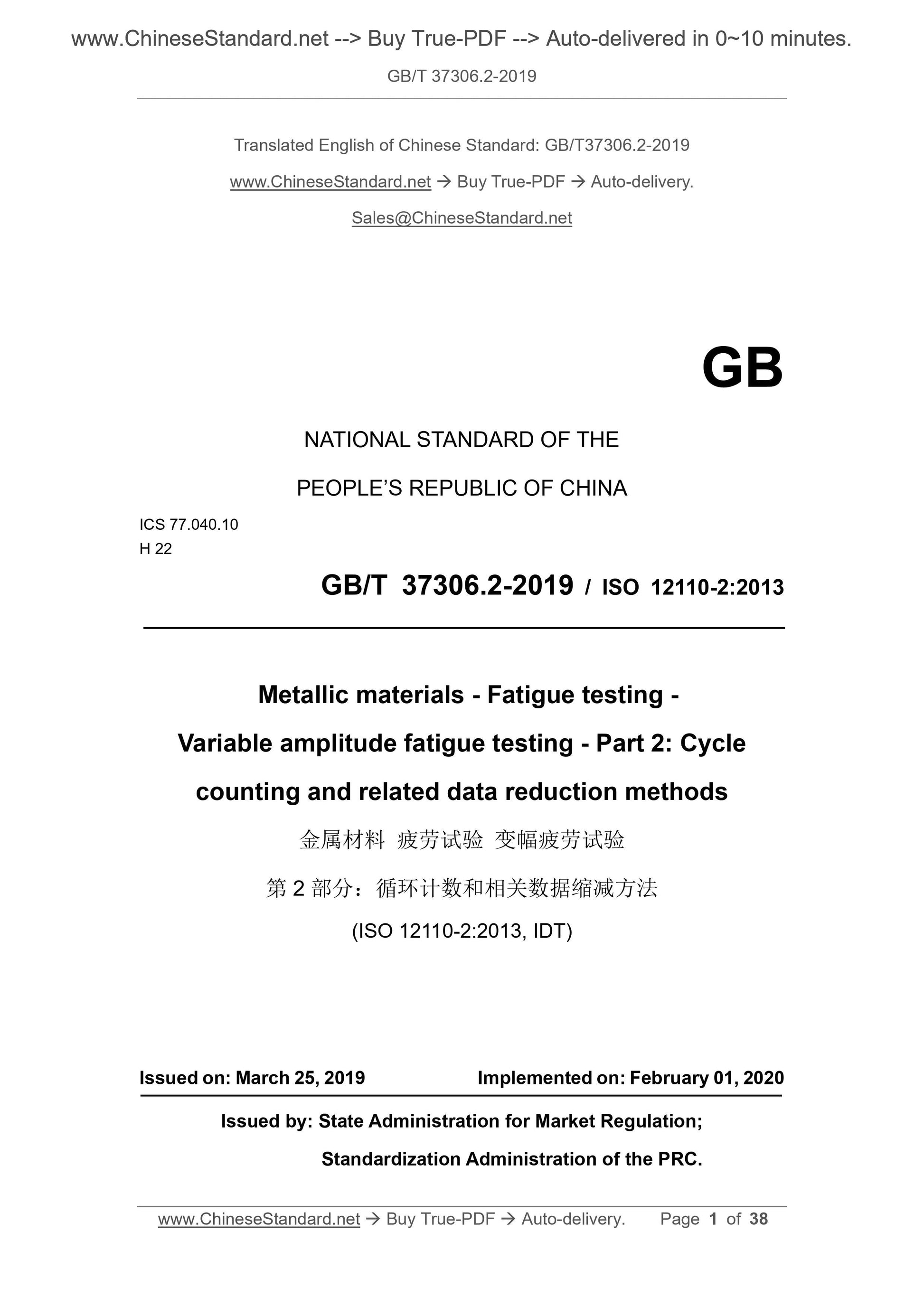
GB/T 37306.2-2019
Metallic materials--Fatigue testing--Variable amplitude fatigue testing--Part 2. Cycle counting and related data reduction methods
ICS 77.040.10
H22
National Standards of People's Republic of China
Metal material fatigue test variable amplitude fatigue test
Part 2. Loop Counting and Related Data Reduction Methods
Part 2. Cyclecountingandrelateddatareductionmethods
(ISO 12110-2.2013, IDT)
Published on.2019-03-25
2020-02-01 implementation
State market supervision and administration
China National Standardization Administration issued
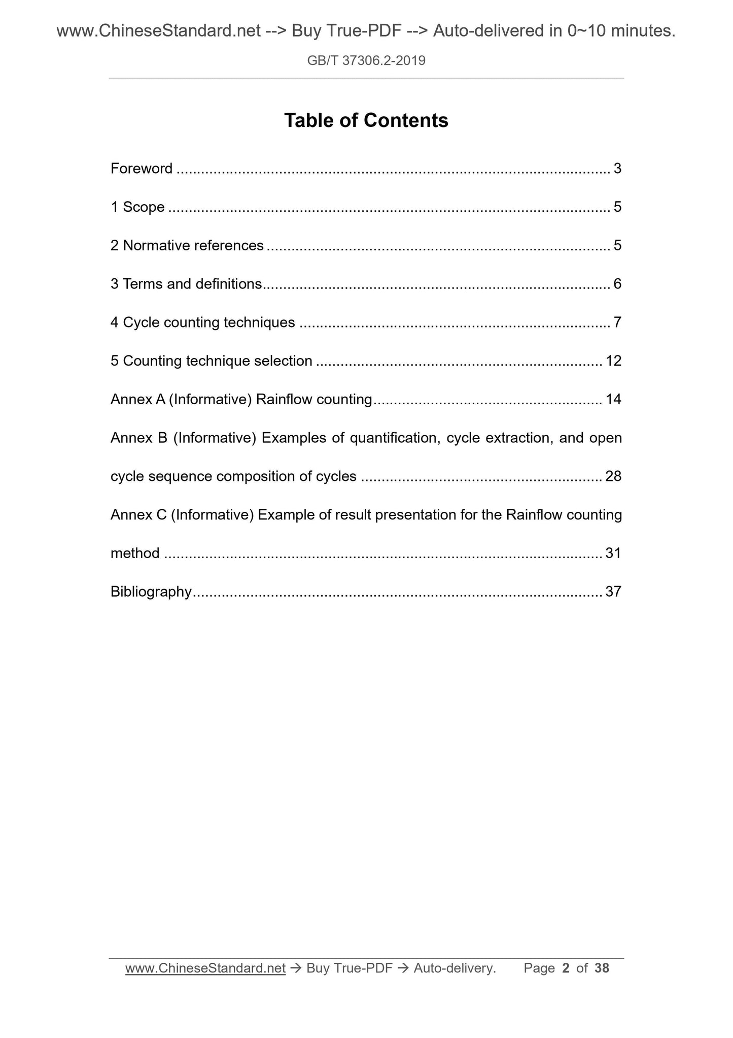
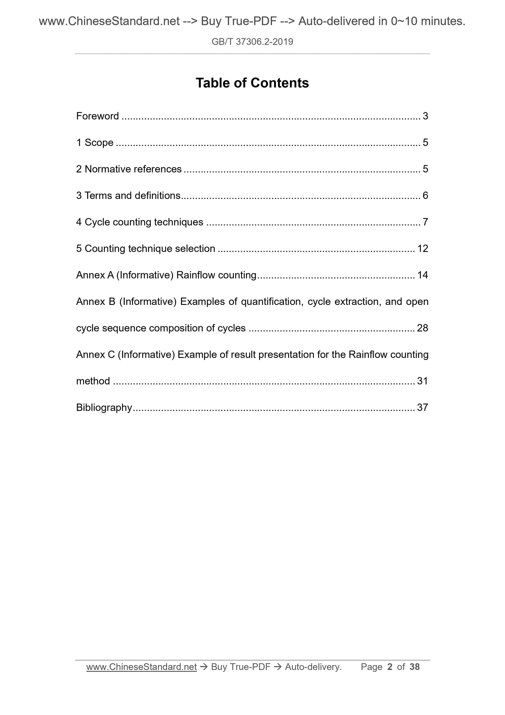
Content
Foreword I
1 range 1
2 Normative references 1
3 Terms and Definitions 1
4 loop counting method 2
5 counting method selection 6
Appendix A (informative appendix) Rainflow counting method 7
Appendix B (informative) Example of composition of open loop sequences in quantification, loop extraction, and loops 17
Appendix C (informative) Example of rain flow counting result report 20
Reference 26
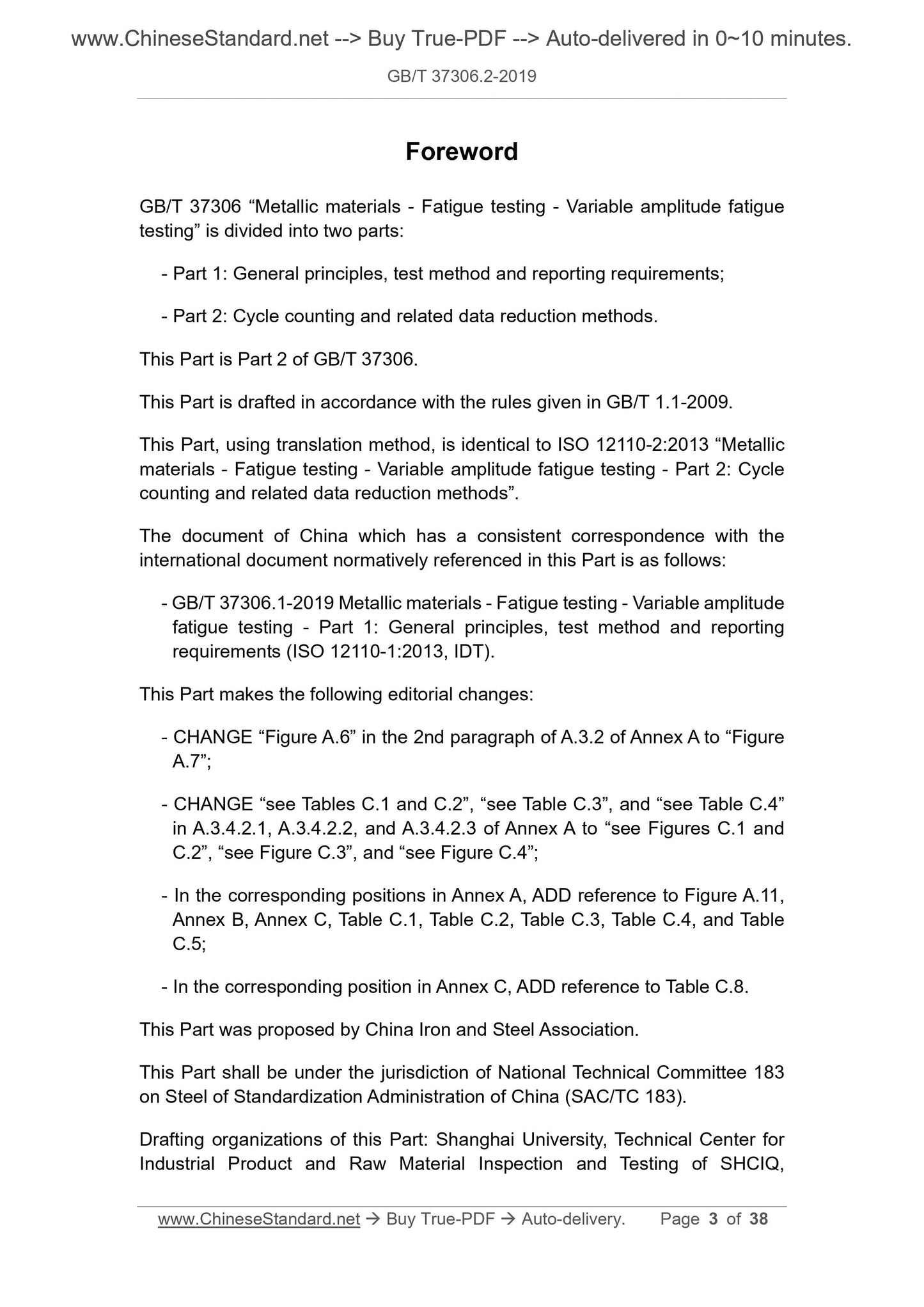
Foreword
GB/T 37306 "Metal material fatigue test variable amplitude fatigue test" is divided into two parts.
--- Part 1. General, test methods and reporting requirements;
--- Part 2. Loop count and related data reduction methods.
This part is the second part of GB/T 37306.
This part is drafted in accordance with the rules given in GB/T 1.1-2009.
This part uses the translation method equivalent to ISO 12110-2.2013 "Metal material fatigue test variable amplitude fatigue test part 2.
Loop Count and Related Data Reduction Methods.
The documents of our country that have a consistent correspondence with the international documents referenced in this part are as follows.
--- GB/T 37306.1-2019 Metallic materials - Fatigue test - Amplitude fatigue test - Part 1. General, test methods and
Reporting requirements (ISO 12110-1.2013, IDT).
This section has made the following editorial changes.
--- Amend "Figure A.6" in the second paragraph of A.3.2 of Appendix A to "Figure A.7";
--- "See Tables C.1 and C.2", "See Table C.3" and "Parameters" in A.3.4.2.1, A.3.4.2.2 and A.3.4.2.3 of Appendix A.
See Table C.4" revised to "see Figure C.1 and Figure C.2", "see Figure C.3" and "see Figure C.4";
---In the corresponding position in Appendix A, reference is made to Figure A.11, Appendix B, Appendix C, Table C.1, Table C.2, Table C.3, Table C.4 and
Table C.5;
--- Add a corresponding reference to Table C.8 in Appendix C.
This part was proposed by the China Iron and Steel Association.
This part is under the jurisdiction of the National Steel Standardization Technical Committee (SAC/TC183).
This section drafted by. Shanghai University, Shanghai Entry-Exit Inspection and Quarantine Bureau Industrial Products and Raw Materials Testing Technology Center, Guangzhou University, Zhejiang
Wanliyang Co., Ltd., Shenzhen Wantest Testing Equipment Co., Ltd.
Drafters of this section. Wang Hongbin, Li Qian, Wu Yiwen, Shen Wenquan, Zhou Wei, Xu Zhonggen, Chen Zhuo, Qin Ziwei, Huang Xing.
Metal material fatigue test variable amplitude fatigue test
Part 2. Loop Counting and Related Data Reduction Methods
1 Scope
This part of GB/T 37306 specifies methods for cyclic counting and data reduction for variable amplitude fatigue testing.
Cycle counts are binding for each test or test series, and various methods of data reduction are optional.
This section supports ISO 12110-1, which contains general requirements for variable amplitude fatigue tests, test methods, and reporting requirements.
This section applies to all load types and the term “load” refers to force, stress or strain.
The following items are outside the scope of this section.
--- Constant amplitude fatigue test with isolated overload or underload phenomenon;
---Experiment of parts or structural parts;
--- Environmental effects such as corrosion, temperature-dependent creep caused by frequency and waveform effects;
--- Multi-axis loading.
Note 1. Phase is critical when performing constant amplitude or variable amplitude controlled loading multi-axis tests.
Note 2. Frequency changes during cycling are outside the scope of this section, and subsequent chapters only deal with constant frequency cycling.
2 Normative references
The following documents are indispensable for the application of this document. For dated references, only dated versions apply to this article.
Pieces. For undated references, the latest edition (including all amendments) applies to this document.
Metallic materials -- Fatigue test -- Fatigue test -- Part 1 . General rules, test methods and reporting requirements
(ISO 12110-1, Metalic materials-Fatiguetesting-Variableamplitudefatiguetesting-Part 1.
Generalprinciples, testmethodandreportingrequirements)
3 Terms and definitions
The following terms and definitions defined by ISO 12110-1 apply to this document.
3.1
Average load crossing number meancrossing
Within a given length history, the load-time history passes through the average load with either a positive or negative slope, or both.
The number of levels.
Note. For the purpose of cycle counting, the average number of load passes can also be defined as the reference load level level.
3.2
Range range
Algebraic difference between two consecutive foldback points.
Note 1. In the case of variable amplitude loading, the definition of the range varies depending on the counting method used. For example, the "total range" is defined as the highest of a given load-time history.
The algebraic difference between the peak and the lowest valley (the absolute maximum and the absolute minimum, respectively).
Note 2. When using different methods for cycle counting, the difference between the peak and valley values of the discontinuous load is usually used as the range. But in practice, the definition of "scope"
It has been broadened and therefore can include such continuous load peak and valley types.
3.3
Reference load referenceload
The load level set for counting, the load change is superimposed thereon.
Note 1. The reference load can be the same as the average load of the load-time history, but this is not required.
3.4
Turnback point reversal
The point at which the first derivative of the load-time history changes sign (from positive to negative or from negative to positive).
Note 1. The return point appears on the peak or valley.
3.5
Irregular factor
Characterization of signal irregularities, ie the number of cycles without crossing the mean, I=N0/Np.
Note 1. N0 is the average number of load penetration stages.
Note 2. Np is the number of peaks.
3.6
Average load level mean-loadlevel
The average of the peak and valley values.
4 loop counting method
4.1 General
Loop counts are often used to reflect irregular load-time history. It can give a simulation of the actual sample or component being studied.
The number of different size loops for the case.
Note. The definition of the loop varies depending on the loop count method used.
Cycle counts can also be cycle counted for load-time history of forces, stresses, strains, deflection angles, or other loading parameters.
There are the following loop counting methods.
---Peak-level counting method;
--- Peak counting method;
---Simple range counting method;
--- Range pair counting method;
--- Rain flow counting method.
4.2 Cycle counting method
4.2.1 Loading signal sampling
The recording of the loaded signal typically involves the continuous evolution of the measured signal (analog or digital) over time. If the original load
The load-time history is an analog signal, then it needs to be converted into a digital file in order to be able to perform subsequent calculations of the load-time history.
Machine processing, including signal sampling, that is, sampling at regular intervals.
Take the following precautions, the digital signal can represent the real analog signal.
---Filter the output signal to eliminate noise and other disturbances that are not related to the fatigue process. These noises and other disturbances are usually true
Part of the Dutch-time history;
--- Sampling frequency should be such that each simulated loading cycle contains at least 20 sampling points, and at least the actual or expected analog signal is observed
20 times the maximum frequency.
The original analog signal should be filtered according to ISO 12110-1.
4.2.2 Threading counting method
4.2.2.1 The results of the pass count are shown in Figure 1. Whenever the positive slope portion of the load time history crosses the reference load level level
Record a number at a preset level, whenever the negative slope portion of the load time history crosses a certain pre-level below the reference load level
Also count a number when setting the level. The number of stages of the reference load level is usually calculated by the number of stages in the positive slope portion of the load time history.
Count. There is no essential difference between positive or negative slope crossing counts. This distinction is made only to reduce the number of penetrations by half.
4.2.2.2 In engineering practice, the run-level count often specifies constraints to eliminate small amplitude changes that may cause large counts. This can also
This is done by filtering small load fluctuations before the cycle count. The second method is not counting at the reference load level, but at
A lower auxiliary level is set at each level above the reference load, when the auxiliary level is above the level of the adjacent two levels.
The load time history is recorded as a number of times when the positive slopes intersect; similarly, another level is set at each level below the reference load.
A high level of assist is also counted when the assist level intersects the negative slope portion of the load time history through the adjacent two levels.
Figure 1b) illustrates this second method. A variation of the second method is to use the same level for all count levels above the reference load.
The lower auxiliary level also uses the same higher auxiliary level for all count levels below the reference load. In this case
Below, the load levels are usually not evenly distributed.
4.2.2.3 The most common cycle counts in fatigue analysis are derived from the run-level counting method by first constructing the largest possible cycle,
The second largest loop is then constructed, and so on, until all levels of wearthrough are used. The return point assumes the middle water between the load levels
Flat.
The loop count processing method is shown in Figure 1c). It should be noted that once the loop count is obtained, these loops can be any desired
The order is loaded, but at the same time this order will have an effect on the degree of fatigue damage. Other loop construction methods can also be used.
4.2.3 Peak Counting Method
4.2.3.1 The peak count method needs to determine the occurrence of a relative maximum or minimum load value. This method requires a peak above the reference load level
Counting is performed and the valley below the reference load level is counted as shown in Figure 2a). Peak and valley count results are usually recorded separately
record. Another way to count this method is to count all peaks and valleys without considering the reference load.
4.2.3.2 In order to remove the effects of small amplitude loads, the mean crossing-peak counting method is often used. Don't have to count all the peaks and valleys,
It is only necessary to count the maximum peak or maximum valley between two consecutive mean crossings, as shown in Figure 2b).
4.2.3.3 The most common cycle counts in fatigue analysis are derived from the peak count method by first using the highest peak and lowest
The valley builds the largest possible loop, then constructs the second largest loop, and so on, until all peak counts are used. See this treatment method
Figure 2c). It should be noted that once the loop count is obtained then these loops can be loaded in any desired order, but at the same time
The order will have a certain impact on the degree of fatigue damage. Alternative methods of other cyclic constructions can also be used, such as randomly selecting peak-to-valley
Value pair.
4.2.4 Simple range counting method
4.2.4.1 Simple range counting method is shown in Figure 3. This method can be used to count positive ranges, negative ranges or both ranges. in case
Counting only positive or negative ranges, each range is treated as a loop count. If both the positive range and the negative range are counted, then each range
Count as a half cycle. A range smaller than the preset level is usually ignored before counting.
4.2.4.2 The average load also affects the measured fatigue results, so the average of each range is also important and the range average should also be counted.
This method is called a simple range-average counting method.
For the example in Figure 3, the results of the simple range-average count are given in the table of Figure 3 as a matrix of range-average values.
Horizontal counting
twenty three
-1 2
-twenty one
-3 1
a) Horizontal pass count
Horizontal counting
twenty three
0 0
-1 1
-twenty one
-3 1
b) Limit horizontal pass count
Range (horizontal) loop count
twenty one
c) a cycle derived from the horizontal pass count a)
Description.
X --- time;
Y --- load level.
Figure 1 Example of the wear level counting method
Horizontal counting
3.5 2
2.5 1
1.5 2
-1.5 1
-2.5 1
-2.7 1
-3.5 1
a) Peak count
Horizontal counting
3.5 2
-3.5 1
b) Mean pass-peak count
Horizontal counting
6.2 1
3 1.5
c) Cycle from peak count a)
Description.
X --- time;
Y --- load level.
Figure 2 Example of peak counting method
Range (horizontal) cycle count history change segment
6 0.5 EF
4 1.5 BC-FG-HI
3 1 DE-GH
2 1.5 AB-CD-IJ
Average load (horizontal)
-2 -1.5 -1 -0.5 0 0.5 1 1.5 2
range
(Level)
2 1 0.5
3 0.5 0.5
4 1 0.5
6 0.5
Description.
X --- time;
Y --- load level.
Figure 3 Example of a simple range counting method - both the positive range and the negative range are counted
4.2.5 Rainflow counting method
See ...
Share
