1
/
of
12
www.ChineseStandard.us -- Field Test Asia Pte. Ltd.
GB/T 37471-2019 English PDF (GB/T37471-2019)
GB/T 37471-2019 English PDF (GB/T37471-2019)
Regular price
$610.00
Regular price
Sale price
$610.00
Unit price
/
per
Shipping calculated at checkout.
Couldn't load pickup availability
GB/T 37471-2019: Intelligent transportation systems - Lane change decision aid systems - Performance requirements and test procedures
Delivery: 9 seconds. Download (& Email) true-PDF + Invoice.
Get Quotation: Click GB/T 37471-2019 (Self-service in 1-minute)
Historical versions (Master-website): GB/T 37471-2019
Preview True-PDF (Reload/Scroll-down if blank)
GB/T 37471-2019
GB
NATIONAL STANDARD OF THE
PEOPLE’S REPUBLIC OF CHINA
ICS 03.220.20; 35.240.60
R 87
Intelligent transportation systems - Lane change
decision aid systems - Performance requirements and
test procedures
[ISO 17387:2008, Intelligent transport systems - Lane change decision aid
systems (LCDAS) - Performance requirements and test procedures, NEQ]
ISSUED ON: MAY 10, 2019
IMPLEMENTED ON: DECEMBER 01, 2019
Issued by: State Administration for Market Regulation;
Standardization Administration of PRC.
Table of Contents
Foreword ... 3
Introduction ... 4
1 Scope ... 5
2 Normative references ... 5
3 Terms and definitions ... 5
4 System classification ... 10
5 Functional and performance requirements ... 14
6 Test requirements ... 23
Appendix A (Informative) Example of blind spot warning ... 44
References ... 59
Intelligent transportation systems - Lane change
decision aid systems - Performance requirements and
test procedures
1 Scope
This standard specifies the classification, function and performance
requirements and test requirements of the lane change decision aid system
(LCDAS).
This standard applies to the lane change decision aid system installed in
category M (including category M1, M2, M3) and N (including category N1, N2,
N3) vehicles under forward driving conditions. It is not applicable to the similar
systems installed in category O (including category O1, O2, O3, O4) and L
(including category L1, L2, L3, L4, L5) vehicles.
2 Normative references
The following documents are essential to the application of this document. For
the dated documents, only the versions with the dates indicated are applicable
to this document; for the undated documents, only the latest version (including
all the amendments) are applicable to this standard.
GB 7258-2012 Safety specifications for power-driven vehicles operating on
roads
3 Terms and definitions
The following terms and definitions apply to this document.
3.1
Subject vehicle
A vehicle equipped with a lane change decision aid system.
3.2
Target vehicle
vr(t) - The closing speed, in meters per second (m/s).
3.10
Overtaking speed
The difference between the speed of the subject vehicle and the speed of
the target vehicle during the process of the subject vehicle overtaking the
target vehicle.
Note: When the speed of the subject vehicle is higher than the target vehicle,
the overtaking speed is positive.
3.11
Blind spot warning function
If the target vehicle is detected in the adjacent zone, it will warn the driver of
the subject vehicle.
3.12
Closing vehicle warning function
If a closing vehicle is detected in the rear zone, it will warn the driver of the
subject vehicle.
3.13
Lane change warning function
The function which includes the blind spot warning function and closing
vehicle warning function.
4 System classification
4.1 Classification by coverage zone
4.1.1 Classification basis
LCDAS is classified according to the minimum limit of the required coverage
range, as shown in Table 1.
c) For category A systems, if the radius of the curve is less than X m, the
system may not be able to provide adequate warnings. Among them, X
refers to the limit curve radius of the system work; the radius shall not
exceed 125 m.
d) For category B systems, if the radius of the curve is less than X m, the
system may not be able to provide sufficient warning. Among them, X
refers to the limit curve radius of the system work; the radius shall not
exceed 250 m.
e) For category C systems, if the radius of the curve is less than X m, the
system may not be able to provide sufficient warning. Among them, X
refers to the limit curve radius of the system work; the radius shall not
exceed 500 m.
5 Functional and performance requirements
5.1 LCDAS functional requirements
5.1.1 Inactive working state and basic functions
LCDAS will not provide any warning to the driver when it is inactive. The system
in the inactive state can enter the standby mode. At this time, the system can
still monitor the target vehicle. Because it is in the inactive state, it will not
provide any warning to the driver. The system in the inactive state can also be
turned off directly without entering the standby mode.
5.1.2 Activation conditions
The activation condition is the judging criteria for LCDAS to switch between the
inactive state and the active state. When the activation condition is met, the
LCDAS is switched from the inactive state to the active state, otherwise the
system is switched from the active state to the inactive state. The activation
conditions can be several parallel judgment criteria; the system can use the
activation conditions listed below, but it is not limited to the following:
a) Continuous activation: When the vehicle ignition is switched to "on", the
system will enter the active state.
b) Manual activation: The driver manually operates through a certain device
to control the switching of the system between the inactive state and the
active state. The device can be a button, a switch or a menu-based user
interface, but it is not limited to the above.
c) Turn signal activation: LCDAS can control the switching between the
inactive state and the active state through the turn signal of the subject
Straight-line H - Parallel to the center line of the vehicle and is located 6 m along the
left side of the leftmost side of the subject vehicle;
Straight-line J - Parallel to the center line of the vehicle and is located at the rightmost
edge of the subject vehicle excluding the exterior rearview mirror;
Straight-line K - Parallel to the center line of the vehicle and is located 0.5 m along the
right side of the rightmost side of the subject vehicle;
Straight-line L - Parallel to the center line of the vehicle and is located 3 m along the
right side of the rightmost side of the subject vehicle;
Straight-line M - Parallel to the center line of the vehicle and is located 6 m along the
right side of the rightmost side of the subject vehicle;
Straight-line N - The extension of the rear edge of the vehicle to the left and right ends;
Straight-line O - Parallel to the rear edge of the vehicle and is located 10 m behind it.
Figure 10 -- Location description of warning requirements
5.2.2 Minimum measurable target vehicle
LCDAS shall be able to detect at least one of all motorcycle types as specified
in GB 7258-2012.
5.2.3 Requirements for blind spot warning function
5.2.3.1 Warning requirements for blind spot warning function
The blind spot warning function shall cover adjacent zones, as shown in the
shaded areas 3 and 4 in Figure 10. If the left or right warning requirements are
met, the system shall issue a corresponding blind spot warning; if the warning
requirements are not met, the system shall not issue the blind spot warning;
please refer to the example of blind spot warning in Appendix A. The left and
right blind spot warning requirements must meet the following conditions:
a) The conditions required for the blind spot warning in the left area are as
follows:
1) Any part of the target vehicle has crossed the straight-line B;
2) The target vehicle is completely located in the area behind the straight-
line C;
3) The target vehicle is completely on the left side of the straight-line F;
4) Any part of the target vehicle crosses the straight-line G to the right.
the switch shall have an indicator light.
When the indicator light on the LCDAS switch is on, it prompts the driver
"LCDAS is not working".
5.3.2 LCDAS active state indication
The LCDAS active state indicator can be used to tell the driver of the subject
vehicle that LCDAS is in working state (see 5.1). If the driver can activate or
deactivate the system manually, the system shall contain both the system
inactive state indicator and the active state indicator. The device that activates
the system is a switch, so that the driver can activate or deactivate the system
manually.
LCDAS work instructions shall be visible; meanwhile it shall clearly remind the
driver that "LCDAS is in working state".
5.3.3 LCDAS warning indication
The LCDAS warning reminds the driver of the subject vehicle that the lane
changing behavior is dangerous (see 5.1). When the system is in the warning
state, the LCDAS warning indicator device shall be able to warn.
When in a level 1 warning state (see 5.1), the system warning indication shall
only be visible. When in the warning state of level 2 or above, the system
warning indication can be in various ways including visual, auditory or tactile
warning. This standard suggests that the warning indicator can indicate the area
where the target vehicle is currently located in some way. It is recommended
that the visual warning indicator be installed in a place that is easy to identify
and does not affect the use of the outside rearview mirror. The visual warning
shall be clearly distinguished from other forms of visual signals in the vehicle. If
an audible warning is used, it shall be clearly distinguished from other audible
signals in the vehicle. If a tactile warning is used, it shall be clearly distinguished
from other tactile signals in the vehicle.
5.3.4 LCDAS fault indication
When LCDAS detects a system fault through the self-check function (see 5.4),
the system shall notify the driver through the fault indication function.
The LCDAS fault indication shall clearly indicate the failure of the driver's
system by means of vision, hearing or a combination of vision and hearing.
5.4 Self-check requirements of subject vehicle
After the system is activated, the system shall at least provide the following self-
check functions:
vehicle and the rear edge of the test target vehicle;
d) The test target vehicle is located on the left side of the subject vehicle; it
can measure the lateral clearance between the leftmost side of the subject
vehicle and the rightmost side of the test target vehicle;
e) If the test target vehicle is located on the right side of the subject vehicle,
the lateral clearance between the rightmost side of the subject vehicle and
the leftmost side of the test target vehicle;
f) It can measure the time delay from the moment when the test target vehicle
meets the warning conditions to the moment when the warning is issued;
g) It can measure the time delay from the moment when the warning
condition is no longer met to the moment when the warning ends.
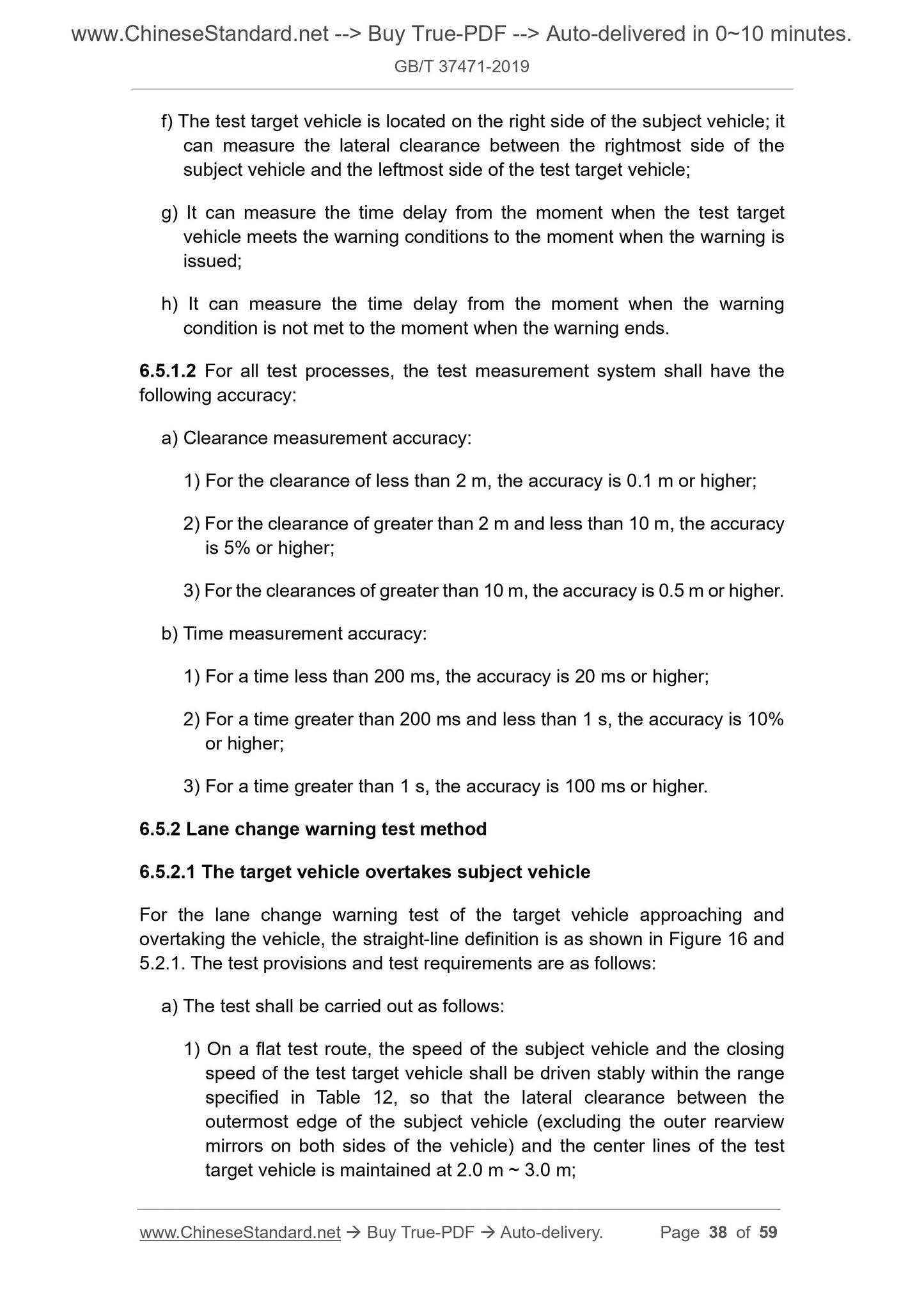
6.3.1.2 For all test processes, the test measurement system has the following
accuracy:
a) Clearance measurement accuracy:
1) For clearances less than 2 m, the accuracy shall be 0.1 m or higher;
2) For clearances greater than 2 m and less than 10 m, the accuracy shall
be 5% or higher;
3) For clearances greater than 10 m, the accuracy shall be 0.5 m or higher.
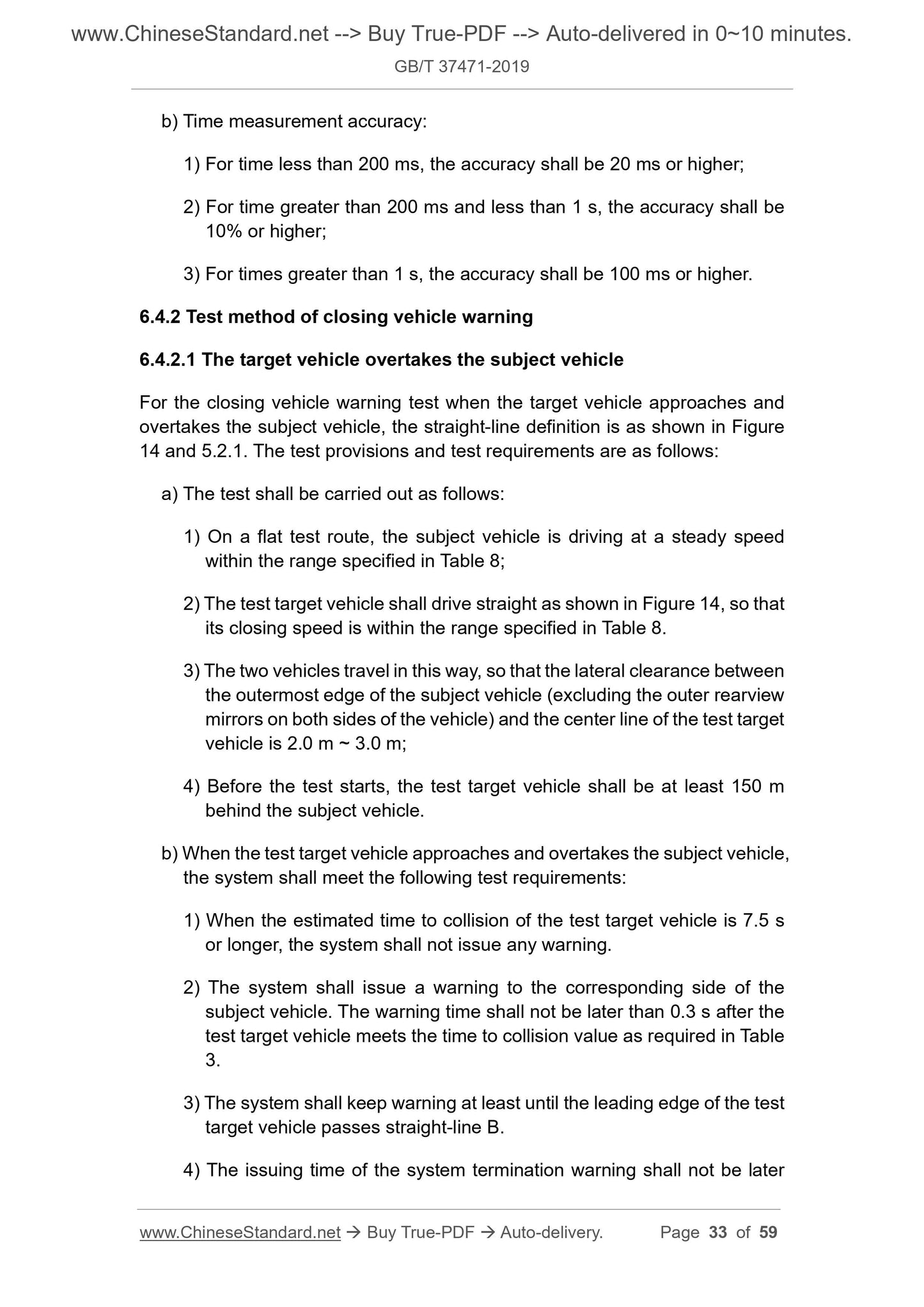
b) Time measurement accuracy:
1) For time less than 200 ms, the accuracy shall be 20 ms or higher;
2) For time greater than 200 ms and less than 1 s, the accuracy shall be
10% or higher;
3) For times greater than 1 s, the accuracy shall be 100 ms or higher.
6.3.2 Blind spot warning test method
6.3.2.1 The target vehicle overtakes the subject vehicle
The blind spot warning test of the target vehicle overtaking the subject vehicle.
The straight-line’s definition is as shown in Figure 11 and 5.2.1. The test steps
and test requirements are as follows:
a) The test shall be carried out according to the following steps:
1) On a straight and flat test route, the subject vehicle shall drive along a
straight-line at a fixed speed of not less than 20 m/s;
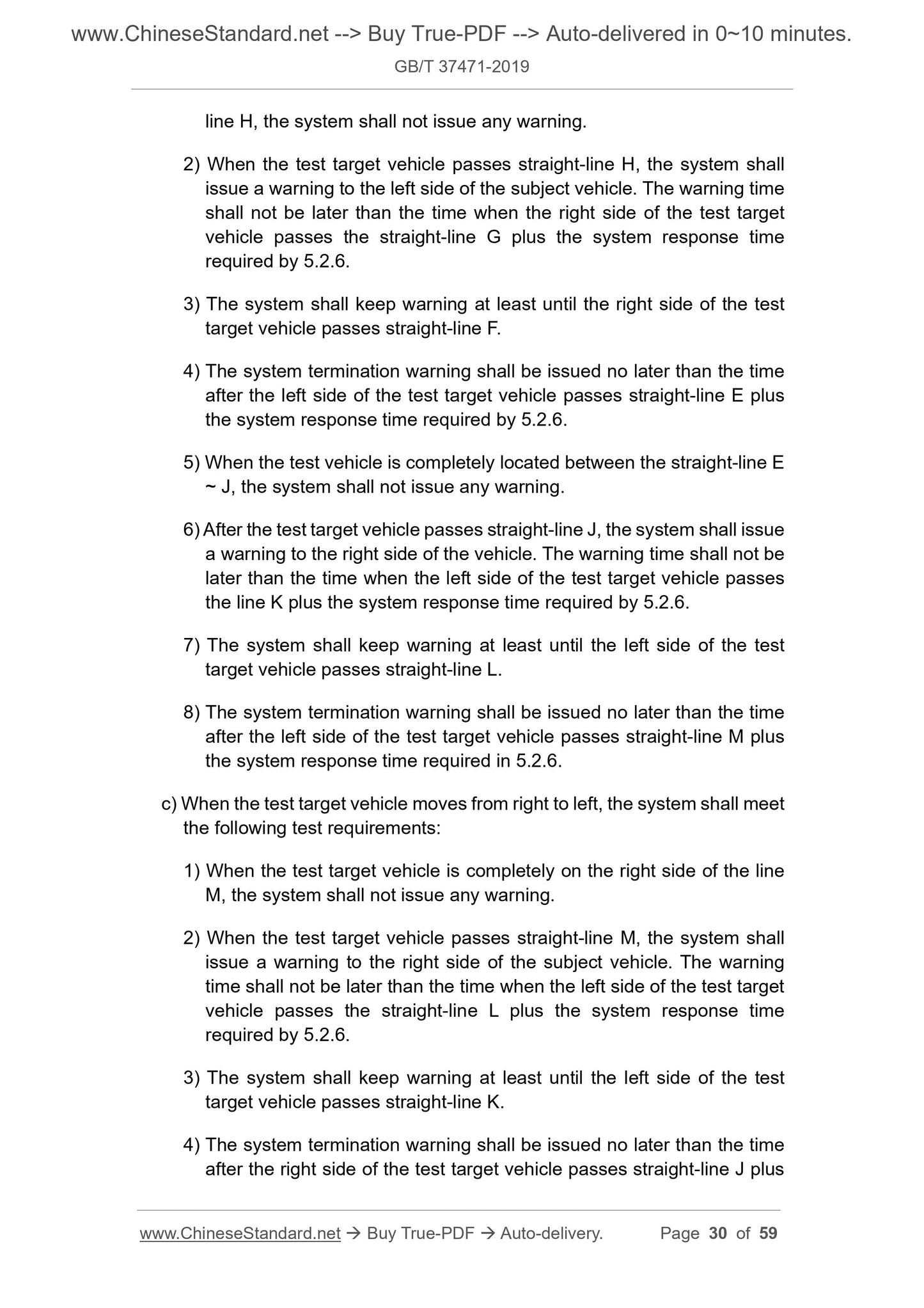
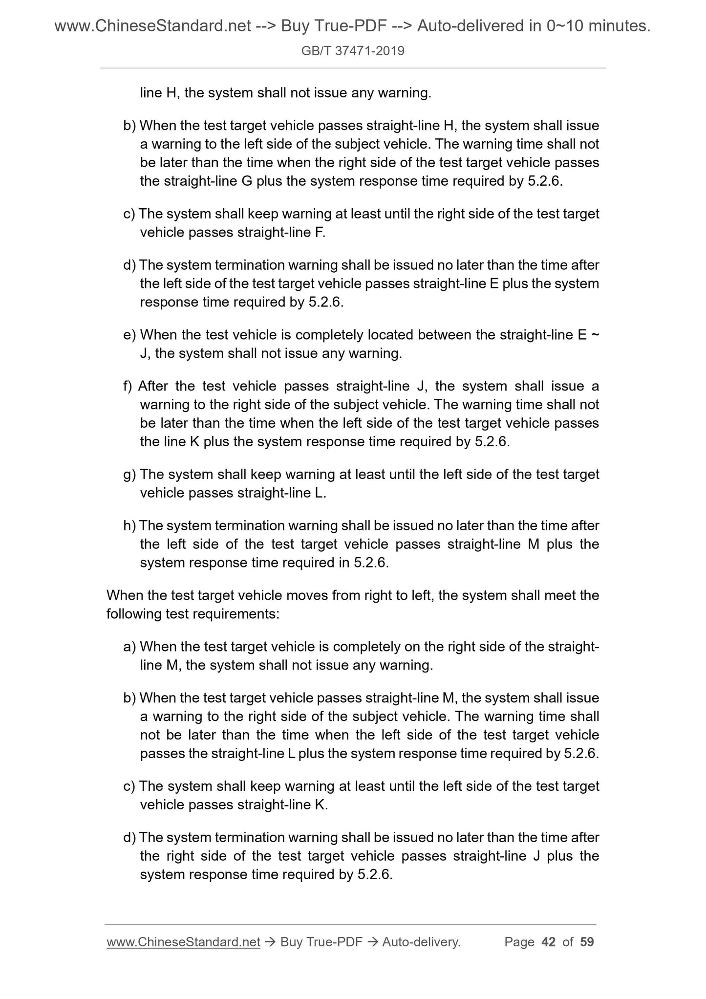
line H, the system shall not issue any warning.
2) When the test target vehicle passes straight-line H, the system shall
issue a warning to the left side of the subject vehicle. The warning time
shall not be later than the time when the right side of the test target
vehicle passes the straight-line G plus the system response time
required by 5.2.6.
3) The system shall keep warning at least until the right side of the test
target vehicle passes straight-line F.
4) The system termination warning shall be issued no later than the time
after the left side of the test target vehicle passes straight-line E plus
the system response time required by 5.2.6.
5) When the test vehicle is completely located between the straight-line E
~ J, the system shall not issue any warning.
6) After the test target vehicle passes straight-line J, the system shall issue
a warning to the right side of the vehicle. The warning time shall not be
later than the time when the left side of the test target vehicle passes
the line K plus the system response time required by 5.2.6.
7) The system shall keep warning at least until the left side of the test
target vehicle passes straight-line L.
8) The system termination warning shall be issued no later than the time
after the left side of the test target vehicle passes straight-line M plus
the system response time required in 5.2.6.
c) When the test target vehicle moves from right to left, the system shall meet
the following test requirements:
1) When the test target vehicle is completely on the right side of the line
M, the system shall not issue any warning.
2) When the test target vehicle passes straight-line M, the system shall
issue a warning to the right side of the subject vehicle. The warning
time shall not be later than the time when the left side of the test target
vehicle passes the straight-line L plus the system response time
required by 5.2.6.
3) The system shall keep warning at least until the left side of the test
target vehicle passes straight-line K.
4) The system termination warning shall be issued no later than the time
after the right side of the test target vehicle passes straight-line J plus
b) Time measurement accuracy:
1) For time less than 200 ms, the accuracy shall be 20 ms or higher;
2) For time greater than 200 ms and ...
Share
