1
/
of
7
www.ChineseStandard.us -- Field Test Asia Pte. Ltd.
GB/T 38719-2020 English PDF (GB/T38719-2020)
GB/T 38719-2020 English PDF (GB/T38719-2020)
Regular price
$265.00
Regular price
Sale price
$265.00
Unit price
/
per
Shipping calculated at checkout.
Couldn't load pickup availability
GB/T 38719-2020: Metallic Materials - Tube - Determination of Biaxial Stress-strain Curve of Tube by Hydro-bulging Test
Delivery: 9 seconds. Download (& Email) true-PDF + Invoice.
Get Quotation: Click GB/T 38719-2020 (Self-service in 1-minute)
Historical versions (Master-website): GB/T 38719-2020
Preview True-PDF (Reload/Scroll-down if blank)
GB/T 38719-2020
GB
NATIONAL STANDARD OF THE
PEOPLE’S REPUBLIC OF CHINA
ICS 77.040.10
H 22
Metallic Materials - Tube - Determination of Biaxial
Stress-strain Curve of Tube by Hydro-bulging Test
ISSUED ON: MARCH 31, 2020
IMPLEMENTED ON: OCTOBER 1, 2020
Issued by: State Administration for Market Regulation;
Standardization Administration of the People’s Republic of
China.
Table of Contents
Foreword ... 3
Introduction ... 4
1 Scope ... 5
2 Normative References ... 5
3 Terms and Definitions ... 5
4 Symbols and Descriptions ... 6
5 Principle ... 7
6 Equipment ... 8
7 Specimen ... 8
8 Test Procedures ... 9
9 Method for Determining Radius of Curvature, Strain and Stress ... 10
10 Result Processing ... 12
11 Test Report ... 12
Appendix A (normative) Test Equipment ... 14
Appendix B (normative) Speckle Spraying Method ... 17
Appendix C (informative) Determination Method for Equivalent Stress-strain
Curve under Bidirectional Stress State ... 19
Bibliography ... 21
Metallic Materials - Tube - Determination of Biaxial
Stress-strain Curve of Tube by Hydro-bulging Test
1 Scope
This Standard specifies the terms and definitions, symbols and descriptions, test
principles, equipment, specimens, test procedures, calculation of biaxial stress-strain
curves and test reports of the biaxial stress-strain curve hydro-bulging test for metallic
material tubes.
This Standard is applicable to thin-walled metal tubes with a circular section (including
seamless tubes and welded tubes) whose wall thickness is not less than 0.5 mm and
diameter-to-thickness ratio is greater than 20.
2 Normative References
The following documents are indispensable to the application of this document. In
terms of references with a specified date, only versions with a specified date are
applicable to this document. In terms of references without a specified date, the latest
version (including all the modifications) is applicable to this document.
GB/T 228.1 Metallic Materials - Tensile Testing - Part 1: Method of Test at Room
Temperature
GB/T 15825.2 Sheet Metal Formability and Test Methods - Part 2: General Test Rules
3 Terms and Definitions
The following terms and definitions are applicable to this document.
3.1 Digital Image Correlation (DIC) Measurement System
Digital image correlation (DIC) measurement system refers to a measurement system
which adopts the digital image correlation method to track the speckle image of the
deformation of an object, and calculate the three-dimensional coordinates,
displacement and strain of the whole field of the object surface.
3.2 Speckle
Speckle refers to a randomly distributed spot on the surface of a test specimen.
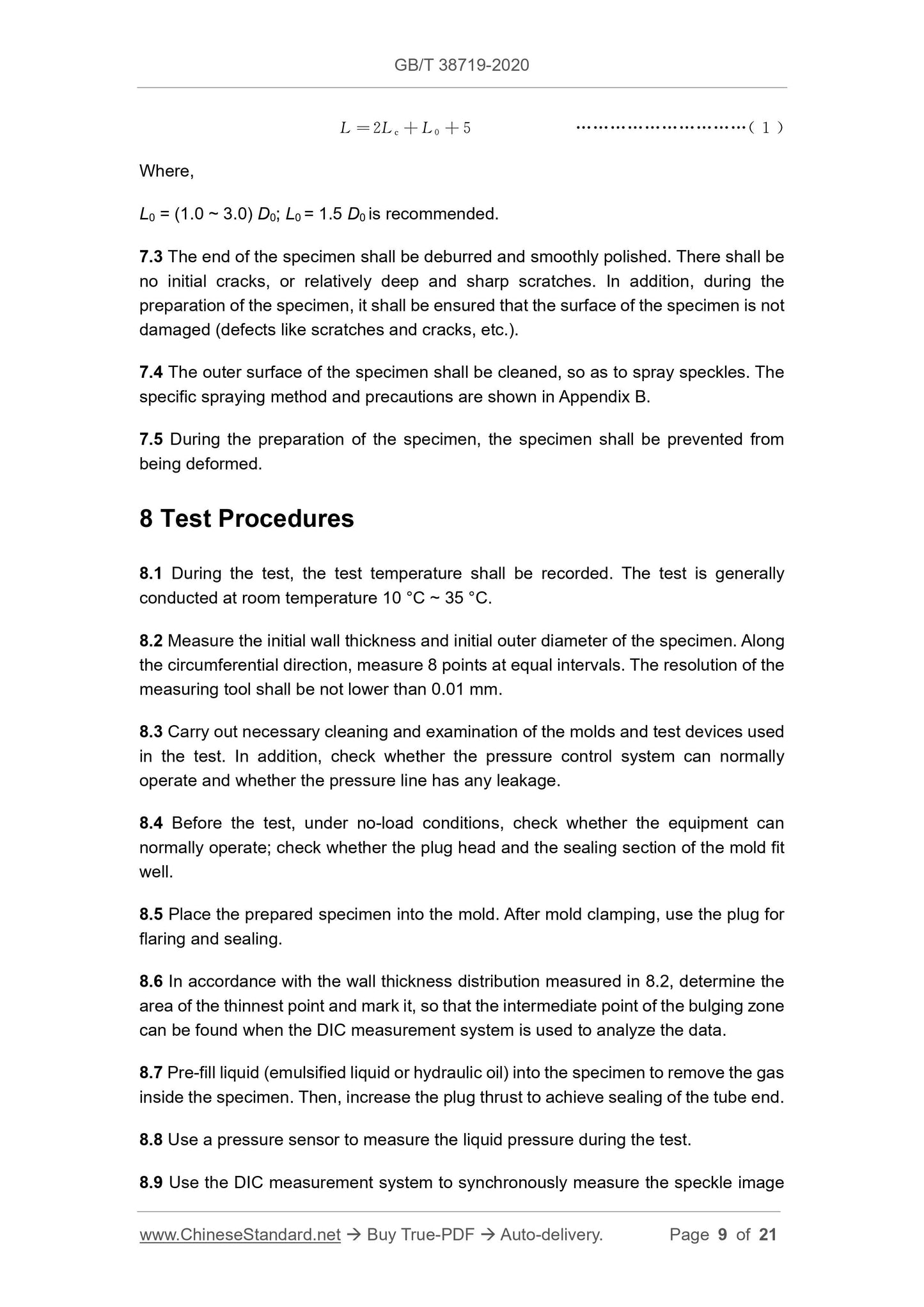
Where,
L0 = (1.0 ~ 3.0) D0; L0 = 1.5 D0 is recommended.
7.3 The end of the specimen shall be deburred and smoothly polished. There shall be
no initial cracks, or relatively deep and sharp scratches. In addition, during the
preparation of the specimen, it shall be ensured that the surface of the specimen is not
damaged (defects like scratches and cracks, etc.).
7.4 The outer surface of the specimen shall be cleaned, so as to spray speckles. The
specific spraying method and precautions are shown in Appendix B.
7.5 During the preparation of the specimen, the specimen shall be prevented from
being deformed.
8 Test Procedures
8.1 During the test, the test temperature shall be recorded. The test is generally
conducted at room temperature 10 °C ~ 35 °C.
8.2 Measure the initial wall thickness and initial outer diameter of the specimen. Along
the circumferential direction, measure 8 points at equal intervals. The resolution of the
measuring tool shall be not lower than 0.01 mm.
8.3 Carry out necessary cleaning and examination of the molds and test devices used
in the test. In addition, check whether the pressure control system can normally
operate and whether the pressure line has any leakage.
8.4 Before the test, under no-load conditions, check whether the equipment can
normally operate; check whether the plug head and the sealing section of the mold fit
well.
8.5 Place the prepared specimen into the mold. After mold clamping, use the plug for
flaring and sealing.
8.6 In accordance with the wall thickness distribution measured in 8.2, determine the
area of the thinnest point and mark it, so that the intermediate point of the bulging zone
can be found when the DIC measurement system is used to analyze the data.
8.7 Pre-fill liquid (emulsified liquid or hydraulic oil) into the specimen to remove the gas
inside the specimen. Then, increase the plug thrust to achieve sealing of the tube end.
8.8 Use a pressure sensor to measure the liquid pressure during the test.
8.9 Use the DIC measurement system to synchronously measure the speckle image
of the surface of the specimen during the test with 8.8.
8.10 In accordance with the same time scale, record and save the pressure data in the
specimen and the deformation data measured by the DIC measurement system. It is
recommended to record at least 60 sets of data every minute. In order to ensure a
sufficient data size, at least 100 images shall be taken during the bulging test.
8.11 In accordance with a certain pressure increase rate (0.05 MPa/s ~ 0.1 MPa/s is
recommended), load until the specimen ruptures. Then, end the test; record the burst
pressure value; save the test data.
8.12 In order to ensure that at least 3 valid test results are obtained, a sufficient number
of specimens shall be prepared.
9 Method for Determining Radius of Curvature, Strain
and Stress
9.1 Radius of Curvature (zp, p)
The required radius of curvature is the axial and circumferential radius of curvature of
the intermediate point of the bulging zone. When the specimen is bulged, the axial
profile of the outer surface of the area near the intermediate point is elliptical, and the
circumferential profile is circular. Take the intermediate point of the bulging zone as the
center, within the DIC measurement range, select a local rectangular area for analysis,
as it is shown in Figure 2. The length l1 of the selected area is recommended to be l1 =
(0.2 ~ 0.5) D0; the width l2 is recommended to be l2 = (0.2 ~ 0.4) l0, or it may be adjusted
in accordance with the actual window size. In the axial direction of the selected area,
uniformly select several points (it is recommended to select at least 5 points; the
distance among the points shall be greater than 2 mm); extract the coordinate
information of the selected points. In accordance with the elliptic equation, use the
least squares fitting method to determine the axial radius of curvature of the
intermediate point of the bulging zone. In the circumferential direction of the selected
area, uniformly select several points (it is recommended to select at least 5 points; the
distance among the points shall be greater than 2 mm); extract the coordinate
information of the selected points. In accordance with the equation of circle, use the
least squares fitting method to determine the circumferential radius of curvature of the
intermediate point of the bulging zone. If necessary, it may also be negotiated to adopt
other fitting methods or calculation methods to determine the radius of curvature.
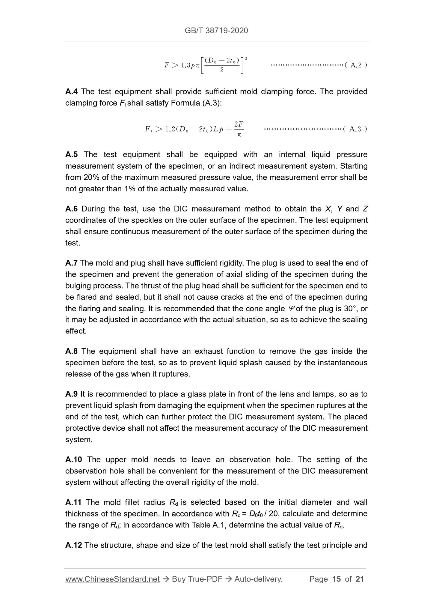
A.4 The test equipment shall provide sufficient mold clamping force. The provided
clamping force Ft shall satisfy Formula (A.3):
A.5 The test equipment shall be equipped with an internal liquid pressure
measurement system of the specimen, or an indirect measurement system. Starting
from 20% of the maximum measured pressure value, the measurement error shall be
not greater than 1% of the actually measured value.
A.6 During the test, use the DIC measurement method to obtain the X, Y and Z
coordinates of the speckles on the outer surface of the specimen. The test equipment
shall ensure continuous measurement of the outer surface of the specimen during the
test.
A.7 The mold and plug shall have sufficient rigidity. The plug is used to seal the end of
the specimen and prevent the generation of axial sliding of the specimen during the
bulging process. The thrust of the plug head shall be sufficient for the specimen end to
be flared and sealed, but it shall not cause cracks at the end of the specimen during
the flaring and sealing. It is recommended that the cone angle of the plug is 30°, or
it may be adjusted in accordance with the actual situation, so as to achieve the sealing
effect.
A.8 The equipment shall have an exhaust function to remove the gas inside the
specimen before the test, so as to prevent liquid splash caused by the instantaneous
release of the gas when it ruptures.
A.9 It is recommended to place a glass plate in front of the lens and lamps, so as to
prevent liquid splash from damaging the equipment when the specimen ruptures at the
end of the test, which can further protect the DIC measurement system. The placed
protective device shall not affect the measurement accuracy of the DIC measurement
system.
A.10 The upper mold needs to leave an observation hole. The setting of the
observation hole shall be convenient for the measurement of the DIC measurement
system without affecting the overall rigidity of the mold.
A.11 The mold fillet radius Rd is selected based on the initial diameter and wall
thickness of the specimen. In accordance with Rd = D0t0 / 20, calculate and determine
the range of Rd; in accordance with Table A.1, determine the actual value of Rd.
A.12 The structure, shape and size of the test mold shall satisfy the test principle and
prevail. It is recommended to use matte self-painting for spraying. After the speckles
are sprayed, the specimen shall be tested as soon as possible, so as to prevent the
speckles from falling off when the specimen is deformed after being placed for a long
time.
NOTE: the spray paint might contain toxic solvents. Please follow the warning
on the spray paint can. DO NOT inhale the sprayed gas. Make sure to use the
spray paint under good ventilation. Avoid the spray paint’s contact with skin and
eyes. The sprayed paint mist is generally flammable, so keep it away from fire
sources. Before spraying, check whether the surface of the specimen is suitable
for painting.
B.3 Quality Requirements for Speckles
The quality of speckles on the surface of the specimen would affect the measurement.
Hence, the speckles sprayed on the surface of the specimen to be tested shall satisfy
the following requirements:
a) In order to obtain a high-contrast random gray-scale distribution image, the
speckles sprayed on the surface of the specimen shall have random
characters, so as to ensure that the pixel area in the reference image matches
the corresponding pixel area in the target image;
b) The used paint shall have sufficient elasticity and strength to prevent the
coating from cracking or falling fall. The speckles shall be able to deform with
the specimen without premature failure;
c) The surface features of the specimen need to have a good contrast to ensure
the accuracy of image matching;
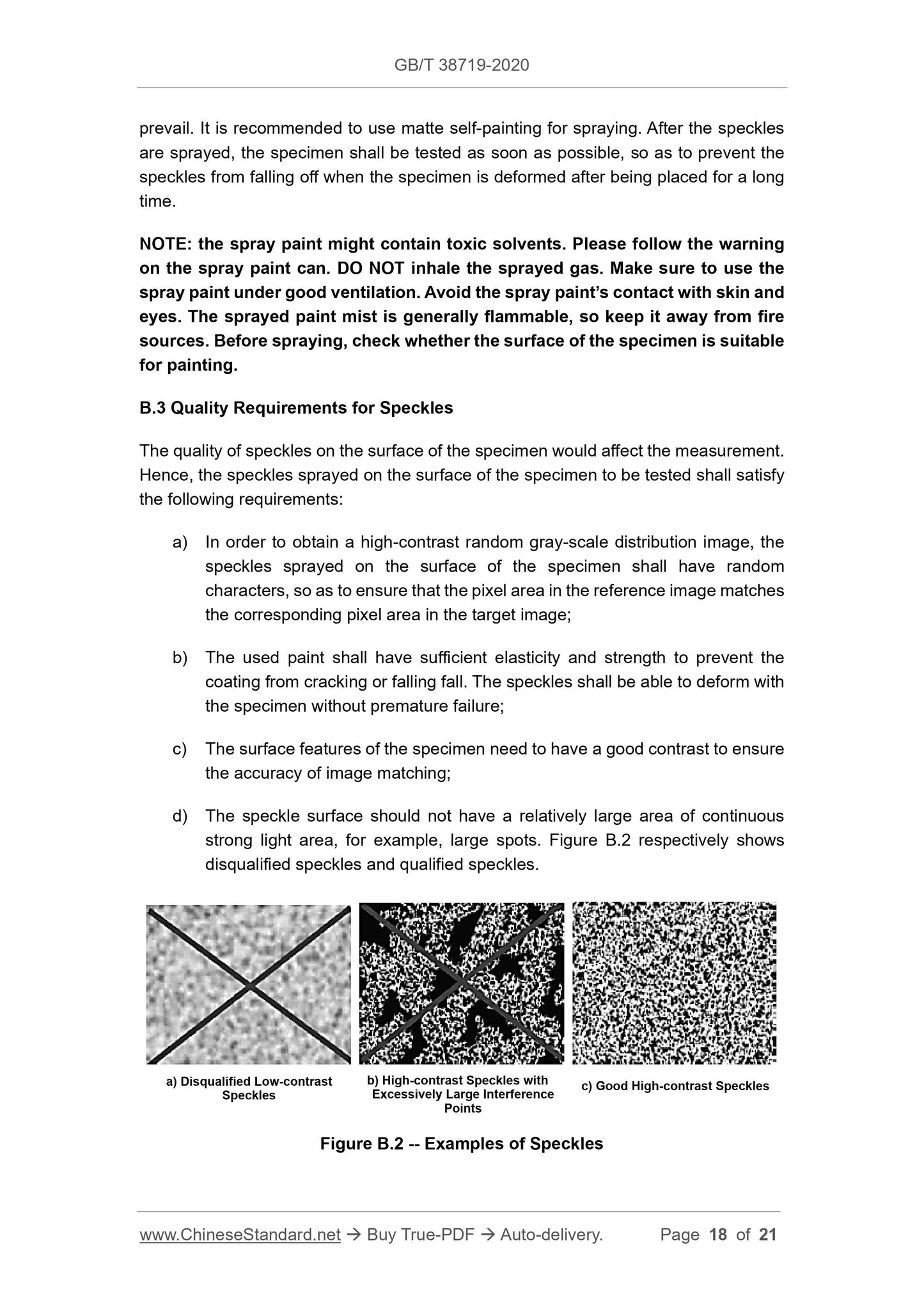
d) The speckle surface should not have a relatively large area of continuous
strong light area, for example, large spots. Figure B.2 respectively shows
disqualified speckles and qualified speckles.
Figure B.2 -- Examples of Speckles
a) Disqualified Low-contrast
Speckles
b) High-contrast Speckles with
Excessively Large Interference
Points
c) Good High-contrast Speckles
GB/T 38719-2020
GB
NATIONAL STANDARD OF THE
PEOPLE’S REPUBLIC OF CHINA
ICS 77.040.10
H 22
Metallic Materials - Tube - Determination of Biaxial
Stress-strain Curve of Tube by Hydro-bulging Test
ISSUED ON: MARCH 31, 2020
IMPLEMENTED ON: OCTOBER 1, 2020
Issued by: State Administration for Market Regulation;
Standardization Administration of the People’s Republic of
China.
Table of Contents
Foreword ... 3
Introduction ... 4
1 Scope ... 5
2 Normative References ... 5
3 Terms and Definitions ... 5
4 Symbols and Descriptions ... 6
5 Principle ... 7
6 Equipment ... 8
7 Specimen ... 8
8 Test Procedures ... 9
9 Method for Determining Radius of Curvature, Strain and Stress ... 10
10 Result Processing ... 12
11 Test Report ... 12
Appendix A (normative) Test Equipment ... 14
Appendix B (normative) Speckle Spraying Method ... 17
Appendix C (informative) Determination Method for Equivalent Stress-strain
Curve under Bidirectional Stress State ... 19
Bibliography ... 21
Metallic Materials - Tube - Determination of Biaxial
Stress-strain Curve of Tube by Hydro-bulging Test
1 Scope
This Standard specifies the terms and definitions, symbols and descriptions, test
principles, equipment, specimens, test procedures, calculation of biaxial stress-strain
curves and test reports of the biaxial stress-strain curve hydro-bulging test for metallic
material tubes.
This Standard is applicable to thin-walled metal tubes with a circular section (including
seamless tubes and welded tubes) whose wall thickness is not less than 0.5 mm and
diameter-to-thickness ratio is greater than 20.
2 Normative References
The following documents are indispensable to the application of this document. In
terms of references with a specified date, only versions with a specified date are
applicable to this document. In terms of references without a specified date, the latest
version (including all the modifications) is applicable to this document.
GB/T 228.1 Metallic Materials - Tensile Testing - Part 1: Method of Test at Room
Temperature
GB/T 15825.2 Sheet Metal Formability and Test Methods - Part 2: General Test Rules
3 Terms and Definitions
The following terms and definitions are applicable to this document.
3.1 Digital Image Correlation (DIC) Measurement System
Digital image correlation (DIC) measurement system refers to a measurement system
which adopts the digital image correlation method to track the speckle image of the
Delivery: 9 seconds. Download (& Email) true-PDF + Invoice.
Get Quotation: Click GB/T 38719-2020 (Self-service in 1-minute)
Historical versions (Master-website): GB/T 38719-2020
Preview True-PDF (Reload/Scroll-down if blank)
GB/T 38719-2020
GB
NATIONAL STANDARD OF THE
PEOPLE’S REPUBLIC OF CHINA
ICS 77.040.10
H 22
Metallic Materials - Tube - Determination of Biaxial
Stress-strain Curve of Tube by Hydro-bulging Test
ISSUED ON: MARCH 31, 2020
IMPLEMENTED ON: OCTOBER 1, 2020
Issued by: State Administration for Market Regulation;
Standardization Administration of the People’s Republic of
China.
Table of Contents
Foreword ... 3
Introduction ... 4
1 Scope ... 5
2 Normative References ... 5
3 Terms and Definitions ... 5
4 Symbols and Descriptions ... 6
5 Principle ... 7
6 Equipment ... 8
7 Specimen ... 8
8 Test Procedures ... 9
9 Method for Determining Radius of Curvature, Strain and Stress ... 10
10 Result Processing ... 12
11 Test Report ... 12
Appendix A (normative) Test Equipment ... 14
Appendix B (normative) Speckle Spraying Method ... 17
Appendix C (informative) Determination Method for Equivalent Stress-strain
Curve under Bidirectional Stress State ... 19
Bibliography ... 21
Metallic Materials - Tube - Determination of Biaxial
Stress-strain Curve of Tube by Hydro-bulging Test
1 Scope
This Standard specifies the terms and definitions, symbols and descriptions, test
principles, equipment, specimens, test procedures, calculation of biaxial stress-strain
curves and test reports of the biaxial stress-strain curve hydro-bulging test for metallic
material tubes.
This Standard is applicable to thin-walled metal tubes with a circular section (including
seamless tubes and welded tubes) whose wall thickness is not less than 0.5 mm and
diameter-to-thickness ratio is greater than 20.
2 Normative References
The following documents are indispensable to the application of this document. In
terms of references with a specified date, only versions with a specified date are
applicable to this document. In terms of references without a specified date, the latest
version (including all the modifications) is applicable to this document.
GB/T 228.1 Metallic Materials - Tensile Testing - Part 1: Method of Test at Room
Temperature
GB/T 15825.2 Sheet Metal Formability and Test Methods - Part 2: General Test Rules
3 Terms and Definitions
The following terms and definitions are applicable to this document.
3.1 Digital Image Correlation (DIC) Measurement System
Digital image correlation (DIC) measurement system refers to a measurement system
which adopts the digital image correlation method to track the speckle image of the
deformation of an object, and calculate the three-dimensional coordinates,
displacement and strain of the whole field of the object surface.
3.2 Speckle
Speckle refers to a randomly distributed spot on the surface of a test specimen.
Where,
L0 = (1.0 ~ 3.0) D0; L0 = 1.5 D0 is recommended.
7.3 The end of the specimen shall be deburred and smoothly polished. There shall be
no initial cracks, or relatively deep and sharp scratches. In addition, during the
preparation of the specimen, it shall be ensured that the surface of the specimen is not
damaged (defects like scratches and cracks, etc.).
7.4 The outer surface of the specimen shall be cleaned, so as to spray speckles. The
specific spraying method and precautions are shown in Appendix B.
7.5 During the preparation of the specimen, the specimen shall be prevented from
being deformed.
8 Test Procedures
8.1 During the test, the test temperature shall be recorded. The test is generally
conducted at room temperature 10 °C ~ 35 °C.
8.2 Measure the initial wall thickness and initial outer diameter of the specimen. Along
the circumferential direction, measure 8 points at equal intervals. The resolution of the
measuring tool shall be not lower than 0.01 mm.
8.3 Carry out necessary cleaning and examination of the molds and test devices used
in the test. In addition, check whether the pressure control system can normally
operate and whether the pressure line has any leakage.
8.4 Before the test, under no-load conditions, check whether the equipment can
normally operate; check whether the plug head and the sealing section of the mold fit
well.
8.5 Place the prepared specimen into the mold. After mold clamping, use the plug for
flaring and sealing.
8.6 In accordance with the wall thickness distribution measured in 8.2, determine the
area of the thinnest point and mark it, so that the intermediate point of the bulging zone
can be found when the DIC measurement system is used to analyze the data.
8.7 Pre-fill liquid (emulsified liquid or hydraulic oil) into the specimen to remove the gas
inside the specimen. Then, increase the plug thrust to achieve sealing of the tube end.
8.8 Use a pressure sensor to measure the liquid pressure during the test.
8.9 Use the DIC measurement system to synchronously measure the speckle image
of the surface of the specimen during the test with 8.8.
8.10 In accordance with the same time scale, record and save the pressure data in the
specimen and the deformation data measured by the DIC measurement system. It is
recommended to record at least 60 sets of data every minute. In order to ensure a
sufficient data size, at least 100 images shall be taken during the bulging test.
8.11 In accordance with a certain pressure increase rate (0.05 MPa/s ~ 0.1 MPa/s is
recommended), load until the specimen ruptures. Then, end the test; record the burst
pressure value; save the test data.
8.12 In order to ensure that at least 3 valid test results are obtained, a sufficient number
of specimens shall be prepared.
9 Method for Determining Radius of Curvature, Strain
and Stress
9.1 Radius of Curvature (zp, p)
The required radius of curvature is the axial and circumferential radius of curvature of
the intermediate point of the bulging zone. When the specimen is bulged, the axial
profile of the outer surface of the area near the intermediate point is elliptical, and the
circumferential profile is circular. Take the intermediate point of the bulging zone as the
center, within the DIC measurement range, select a local rectangular area for analysis,
as it is shown in Figure 2. The length l1 of the selected area is recommended to be l1 =
(0.2 ~ 0.5) D0; the width l2 is recommended to be l2 = (0.2 ~ 0.4) l0, or it may be adjusted
in accordance with the actual window size. In the axial direction of the selected area,
uniformly select several points (it is recommended to select at least 5 points; the
distance among the points shall be greater than 2 mm); extract the coordinate
information of the selected points. In accordance with the elliptic equation, use the
least squares fitting method to determine the axial radius of curvature of the
intermediate point of the bulging zone. In the circumferential direction of the selected
area, uniformly select several points (it is recommended to select at least 5 points; the
distance among the points shall be greater than 2 mm); extract the coordinate
information of the selected points. In accordance with the equation of circle, use the
least squares fitting method to determine the circumferential radius of curvature of the
intermediate point of the bulging zone. If necessary, it may also be negotiated to adopt
other fitting methods or calculation methods to determine the radius of curvature.
A.4 The test equipment shall provide sufficient mold clamping force. The provided
clamping force Ft shall satisfy Formula (A.3):
A.5 The test equipment shall be equipped with an internal liquid pressure
measurement system of the specimen, or an indirect measurement system. Starting
from 20% of the maximum measured pressure value, the measurement error shall be
not greater than 1% of the actually measured value.
A.6 During the test, use the DIC measurement method to obtain the X, Y and Z
coordinates of the speckles on the outer surface of the specimen. The test equipment
shall ensure continuous measurement of the outer surface of the specimen during the
test.
A.7 The mold and plug shall have sufficient rigidity. The plug is used to seal the end of
the specimen and prevent the generation of axial sliding of the specimen during the
bulging process. The thrust of the plug head shall be sufficient for the specimen end to
be flared and sealed, but it shall not cause cracks at the end of the specimen during
the flaring and sealing. It is recommended that the cone angle of the plug is 30°, or
it may be adjusted in accordance with the actual situation, so as to achieve the sealing
effect.
A.8 The equipment shall have an exhaust function to remove the gas inside the
specimen before the test, so as to prevent liquid splash caused by the instantaneous
release of the gas when it ruptures.
A.9 It is recommended to place a glass plate in front of the lens and lamps, so as to
prevent liquid splash from damaging the equipment when the specimen ruptures at the
end of the test, which can further protect the DIC measurement system. The placed
protective device shall not affect the measurement accuracy of the DIC measurement
system.
A.10 The upper mold needs to leave an observation hole. The setting of the
observation hole shall be convenient for the measurement of the DIC measurement
system without affecting the overall rigidity of the mold.
A.11 The mold fillet radius Rd is selected based on the initial diameter and wall
thickness of the specimen. In accordance with Rd = D0t0 / 20, calculate and determine
the range of Rd; in accordance with Table A.1, determine the actual value of Rd.
A.12 The structure, shape and size of the test mold shall satisfy the test principle and
prevail. It is recommended to use matte self-painting for spraying. After the speckles
are sprayed, the specimen shall be tested as soon as possible, so as to prevent the
speckles from falling off when the specimen is deformed after being placed for a long
time.
NOTE: the spray paint might contain toxic solvents. Please follow the warning
on the spray paint can. DO NOT inhale the sprayed gas. Make sure to use the
spray paint under good ventilation. Avoid the spray paint’s contact with skin and
eyes. The sprayed paint mist is generally flammable, so keep it away from fire
sources. Before spraying, check whether the surface of the specimen is suitable
for painting.
B.3 Quality Requirements for Speckles
The quality of speckles on the surface of the specimen would affect the measurement.
Hence, the speckles sprayed on the surface of the specimen to be tested shall satisfy
the following requirements:
a) In order to obtain a high-contrast random gray-scale distribution image, the
speckles sprayed on the surface of the specimen shall have random
characters, so as to ensure that the pixel area in the reference image matches
the corresponding pixel area in the target image;
b) The used paint shall have sufficient elasticity and strength to prevent the
coating from cracking or falling fall. The speckles shall be able to deform with
the specimen without premature failure;
c) The surface features of the specimen need to have a good contrast to ensure
the accuracy of image matching;
d) The speckle surface should not have a relatively large area of continuous
strong light area, for example, large spots. Figure B.2 respectively shows
disqualified speckles and qualified speckles.
Figure B.2 -- Examples of Speckles
a) Disqualified Low-contrast
Speckles
b) High-contrast Speckles with
Excessively Large Interference
Points
c) Good High-contrast Speckles
GB/T 38719-2020
GB
NATIONAL STANDARD OF THE
PEOPLE’S REPUBLIC OF CHINA
ICS 77.040.10
H 22
Metallic Materials - Tube - Determination of Biaxial
Stress-strain Curve of Tube by Hydro-bulging Test
ISSUED ON: MARCH 31, 2020
IMPLEMENTED ON: OCTOBER 1, 2020
Issued by: State Administration for Market Regulation;
Standardization Administration of the People’s Republic of
China.
Table of Contents
Foreword ... 3
Introduction ... 4
1 Scope ... 5
2 Normative References ... 5
3 Terms and Definitions ... 5
4 Symbols and Descriptions ... 6
5 Principle ... 7
6 Equipment ... 8
7 Specimen ... 8
8 Test Procedures ... 9
9 Method for Determining Radius of Curvature, Strain and Stress ... 10
10 Result Processing ... 12
11 Test Report ... 12
Appendix A (normative) Test Equipment ... 14
Appendix B (normative) Speckle Spraying Method ... 17
Appendix C (informative) Determination Method for Equivalent Stress-strain
Curve under Bidirectional Stress State ... 19
Bibliography ... 21
Metallic Materials - Tube - Determination of Biaxial
Stress-strain Curve of Tube by Hydro-bulging Test
1 Scope
This Standard specifies the terms and definitions, symbols and descriptions, test
principles, equipment, specimens, test procedures, calculation of biaxial stress-strain
curves and test reports of the biaxial stress-strain curve hydro-bulging test for metallic
material tubes.
This Standard is applicable to thin-walled metal tubes with a circular section (including
seamless tubes and welded tubes) whose wall thickness is not less than 0.5 mm and
diameter-to-thickness ratio is greater than 20.
2 Normative References
The following documents are indispensable to the application of this document. In
terms of references with a specified date, only versions with a specified date are
applicable to this document. In terms of references without a specified date, the latest
version (including all the modifications) is applicable to this document.
GB/T 228.1 Metallic Materials - Tensile Testing - Part 1: Method of Test at Room
Temperature
GB/T 15825.2 Sheet Metal Formability and Test Methods - Part 2: General Test Rules
3 Terms and Definitions
The following terms and definitions are applicable to this document.
3.1 Digital Image Correlation (DIC) Measurement System
Digital image correlation (DIC) measurement system refers to a measurement system
which adopts the digital image correlation method to track the speckle image of the
Share