1
/
of
10
PayPal, credit cards. Download editable-PDF and invoice in 1 second!
GB/T 38775.2-2020 English PDF (GBT38775.2-2020)
GB/T 38775.2-2020 English PDF (GBT38775.2-2020)
Regular price
$505.00 USD
Regular price
Sale price
$505.00 USD
Unit price
/
per
Shipping calculated at checkout.
Couldn't load pickup availability
Delivery: 3 seconds. Download true-PDF + Invoice.
Get QUOTATION in 1-minute: Click GB/T 38775.2-2020
Historical versions: GB/T 38775.2-2020
Preview True-PDF (Reload/Scroll if blank)
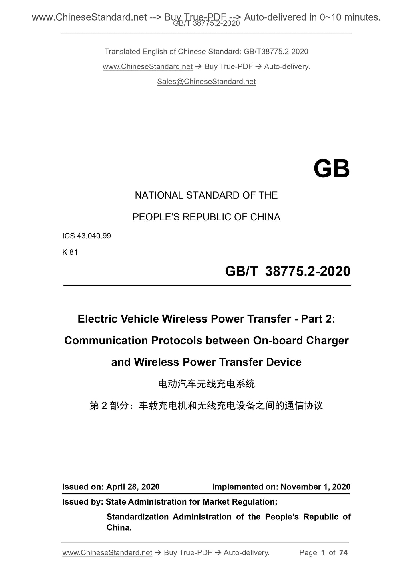
GB/T 38775.2-2020: Electric vehicle wireless power transfer -- Part 2: Communication protocols between on-board charger and wireless power transfer device
GB/T 38775.2-2020
NATIONAL STANDARD OF THE
PEOPLE’S REPUBLIC OF CHINA
ICS 43.040.99
K 81
Electric Vehicle Wireless Power Transfer - Part 2:
Communication Protocols between On-board Charger
and Wireless Power Transfer Device
ISSUED ON: APRIL 28, 2020
IMPLEMENTED ON: NOVEMBER 1, 2020
Issued by: State Administration for Market Regulation;
Standardization Administration of the People’s Republic of
China.
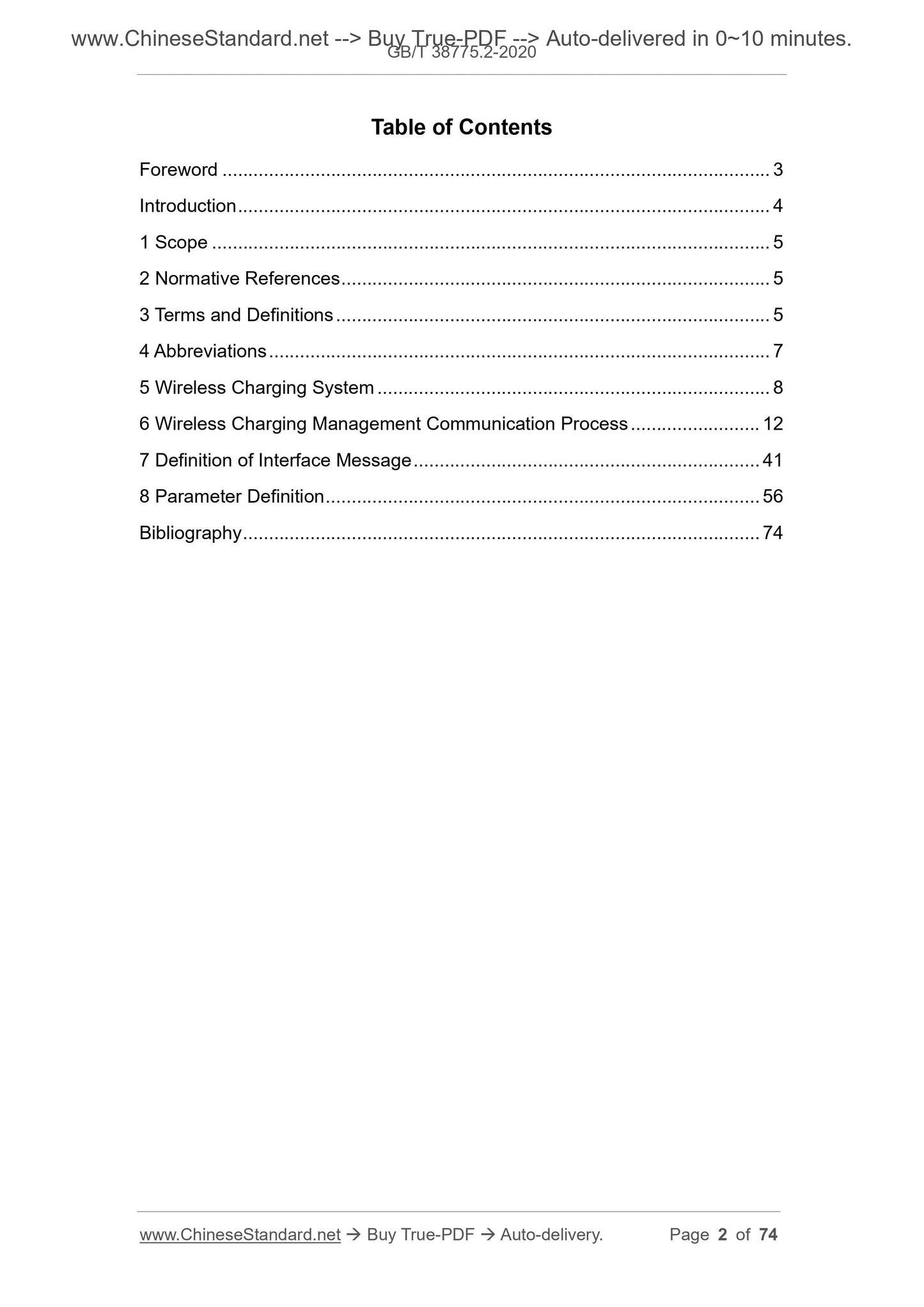
Table of Contents
Foreword ... 3
Introduction ... 4
1 Scope ... 5
2 Normative References ... 5
3 Terms and Definitions ... 5
4 Abbreviations ... 7
5 Wireless Charging System ... 8
6 Wireless Charging Management Communication Process ... 12
7 Definition of Interface Message ... 41
8 Parameter Definition ... 56
Bibliography ... 74
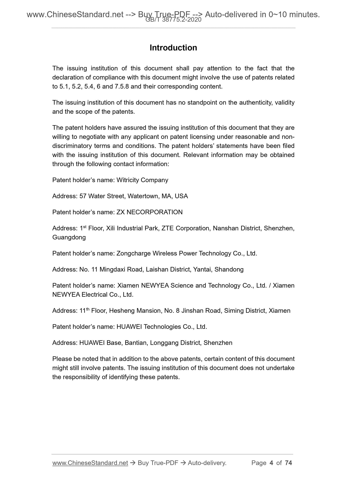
Introduction
The issuing institution of this document shall pay attention to the fact that the
declaration of compliance with this document might involve the use of patents related
to 5.1, 5.2, 5.4, 6 and 7.5.8 and their corresponding content.
The issuing institution of this document has no standpoint on the authenticity, validity
and the scope of the patents.
The patent holders have assured the issuing institution of this document that they are
willing to negotiate with any applicant on patent licensing under reasonable and non-
discriminatory terms and conditions. The patent holders’ statements have been filed
with the issuing institution of this document. Relevant information may be obtained
through the following contact information:
Patent holder’s name: Witricity Company
Address: 57 Water Street, Watertown, MA, USA
Patent holder’s name: ZX NECORPORATION
Address: 1st Floor, Xili Industrial Park, ZTE Corporation, Nanshan District, Shenzhen,
Guangdong
Patent holder’s name: Zongcharge Wireless Power Technology Co., Ltd.
Address: No. 11 Mingdaxi Road, Laishan District, Yantai, Shandong
Patent holder’s name: Xiamen NEWYEA Science and Technology Co., Ltd. / Xiamen
NEWYEA Electrical Co., Ltd.
Address: 11th Floor, Hesheng Mansion, No. 8 Jinshan Road, Siming District, Xiamen
Patent holder’s name: HUAWEI Technologies Co., Ltd.
Address: HUAWEI Base, Bantian, Longgang District, Shenzhen
Please be noted that in addition to the above patents, certain content of this document
might still involve patents. The issuing institution of this document does not undertake
the responsibility of identifying these patents.
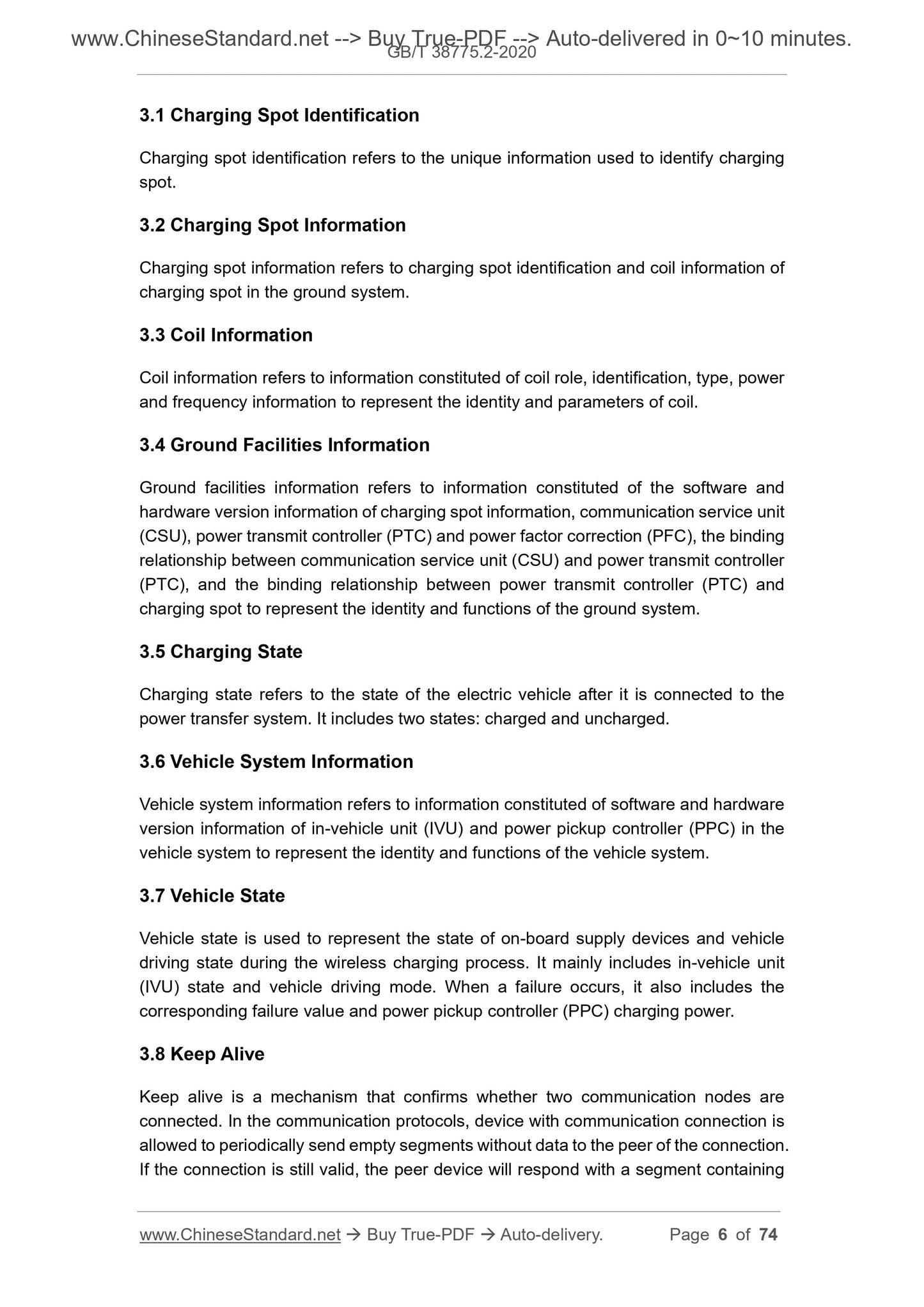
3.1 Charging Spot Identification
Charging spot identification refers to the unique information used to identify charging
spot.
3.2 Charging Spot Information
Charging spot information refers to charging spot identification and coil information of
charging spot in the ground system.
3.3 Coil Information
Coil information refers to information constituted of coil role, identification, type, power
and frequency information to represent the identity and parameters of coil.
3.4 Ground Facilities Information
Ground facilities information refers to information constituted of the software and
hardware version information of charging spot information, communication service unit
(CSU), power transmit controller (PTC) and power factor correction (PFC), the binding
relationship between communication service unit (CSU) and power transmit controller
(PTC), and the binding relationship between power transmit controller (PTC) and
charging spot to represent the identity and functions of the ground system.
3.5 Charging State
Charging state refers to the state of the electric vehicle after it is connected to the
power transfer system. It includes two states: charged and uncharged.
3.6 Vehicle System Information
Vehicle system information refers to information constituted of software and hardware
version information of in-vehicle unit (IVU) and power pickup controller (PPC) in the
vehicle system to represent the identity and functions of the vehicle system.
3.7 Vehicle State
Vehicle state is used to represent the state of on-board supply devices and vehicle
driving state during the wireless charging process. It mainly includes in-vehicle unit
(IVU) state and vehicle driving mode. When a failure occurs, it also includes the
corresponding failure value and power pickup controller (PPC) charging power.
3.8 Keep Alive
Keep alive is a mechanism that confirms whether two communication nodes are
connected. In the communication protocols, device with communication connection is
allowed to periodically send empty segments without data to the peer of the connection.
If the connection is still valid, the peer device will respond with a segment containing
5 Wireless Charging System
5.1 Overview
In structure, the wireless charging system is divided into off-board devices and on-
board devices, between which, there is no direct physical connection. During the
wireless charging process, the off-board devices and on-board devices shall exchange
information through wireless communication, so as to implement the control and
management of the charging process.
During the operation of the wireless charging system, CSU shall effectively
communicate with the electric vehicle control system through IVU, so as to implement
security monitoring of the charging process.
In case B communication, the wireless charging system shall have the capability of
remote comprehensive management on the network side. CSU shall be equipped with
an interface for data communication with WCCMS.
The wireless charging system includes two parts: ground system and vehicle system:
a) Ground system: it includes WCCMS, CSU, PTC, PFC and PrC, etc.;
b) Vehicle system: it includes vehicle control system, IVU, PPC and PuC, etc.
The management and communication system include communication units of WCCMS,
CSU and IVU, etc. PTC, PrC, PPC and PuC constitute the wireless power transfer
system, and implement the transmission of electrical energy from the ground system
to the vehicle system through the wireless interface. PTC of the ground system and
PPC of the vehicle system implement interaction and communication through the
management and communication system. Figure 1 is an architecture diagram of
wireless charging system.
Between PPC and the vehicle control system, there may be a communication interface.
NOTE: this Standard currently does not support scenarios where management and
communication system across multiple operators.
CSU and IVU;
2) Wireless charging monitoring;
3) Measurement processing (optional);
4) Participate in part of charging control, such as: checking whether IVU
user identification and IVU device identification are matching, whether
CSU user identification and CSU device identification are matching, and
charging abnormality handling, etc.
b) CSU: communication service unit, which completes the signaling control of
the ground system, and the communication channel function of the WCCMS
to the ground system, and the vehicle system to the ground system. CSU shall
be equipped with the following functions:
1) Control PTC initiation and stop power supply to PrC;
2) PTC and PFC failure and abnormality detection;
3) Report charging state to IVU;
4) Forward PPC and PTC data with IVU;
5) Check whether primary coil and pickup coil are matching.
In case B communication, CSU shall also be equipped with the following
functions:
1) Take charge of communication between the ground system and the
WCCMS;
2) Report charging state to WCCMS.
c) IVU: in-vehic...
Share
