1
/
of
12
PayPal, credit cards. Download editable-PDF and invoice in 1 second!
GB/T 50312-2016 English PDF (GBT50312-2016)
GB/T 50312-2016 English PDF (GBT50312-2016)
Regular price
$1,520.00 USD
Regular price
Sale price
$1,520.00 USD
Unit price
/
per
Shipping calculated at checkout.
Couldn't load pickup availability
Delivery: 3 seconds. Download true-PDF + Invoice.
Get QUOTATION in 1-minute: Click GB/T 50312-2016
Historical versions: GB/T 50312-2016
Preview True-PDF (Reload/Scroll if blank)
GB/T 50312-2016: Code for engineering acceptance of generic cabling system
GB/T 50312-2016
GB
NATIONAL STANDARD OF THE
PEOPLE’S REPUBLIC OF CHINA
UDC
P GB/T 50312-2016
Code for engineering acceptance of generic cabling system
ISSUED ON: AUGUST 26, 2016
IMPLEMENTED ON: APRIL 01, 2017
Issued by: Ministry of Housing and Urban-Rural Development of PRC.
General Administration of Quality Supervision, Inspection and
Quarantine of PRC.
Table of Contents
Foreword ... 5
1 General provisions ... 7
2 Abbreviation ... 7
3 Environment examination ... 8
4 Examination of equipment and test instrumentation ... 10
5 Examination of equipment installation ... 13
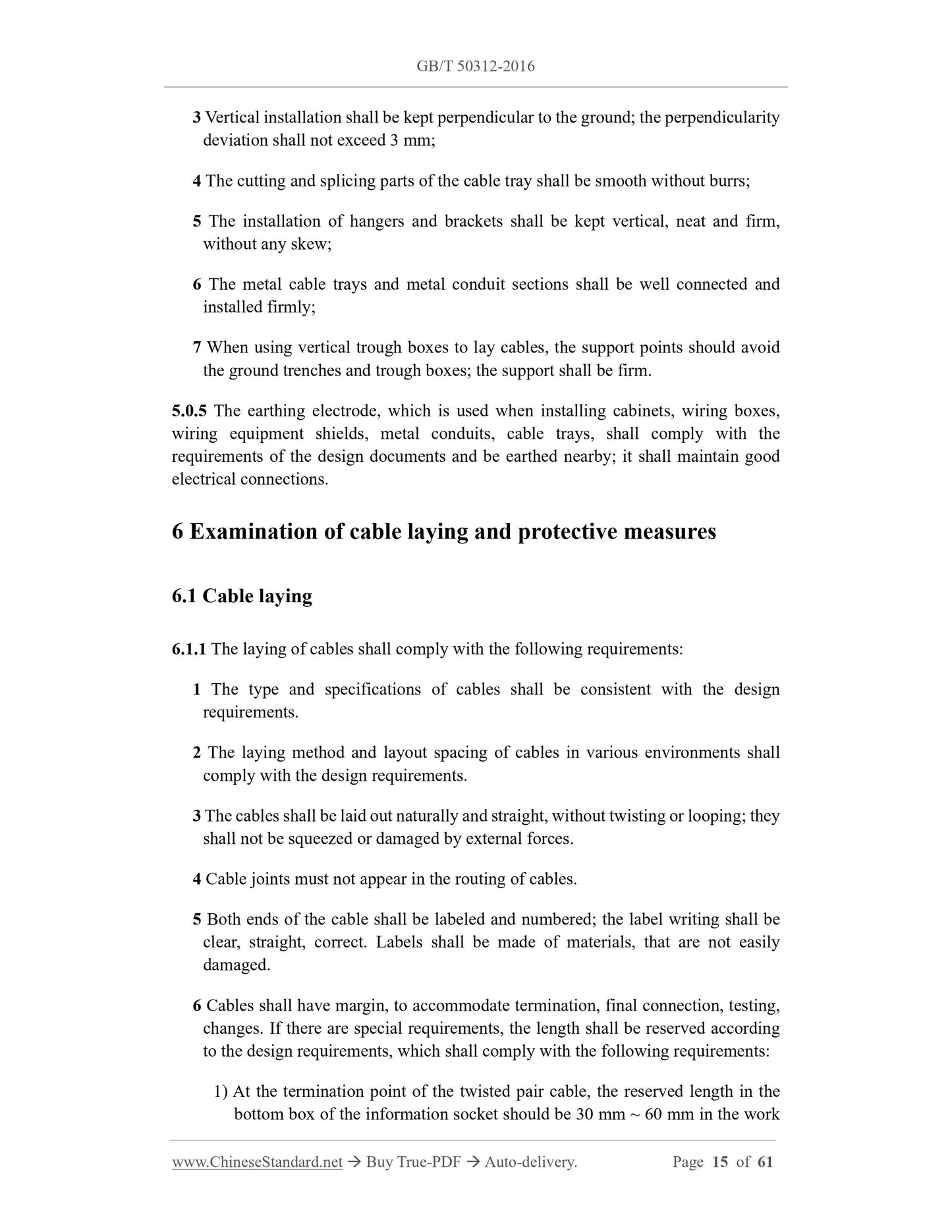
6 Examination of cable laying and protective measures ... 15
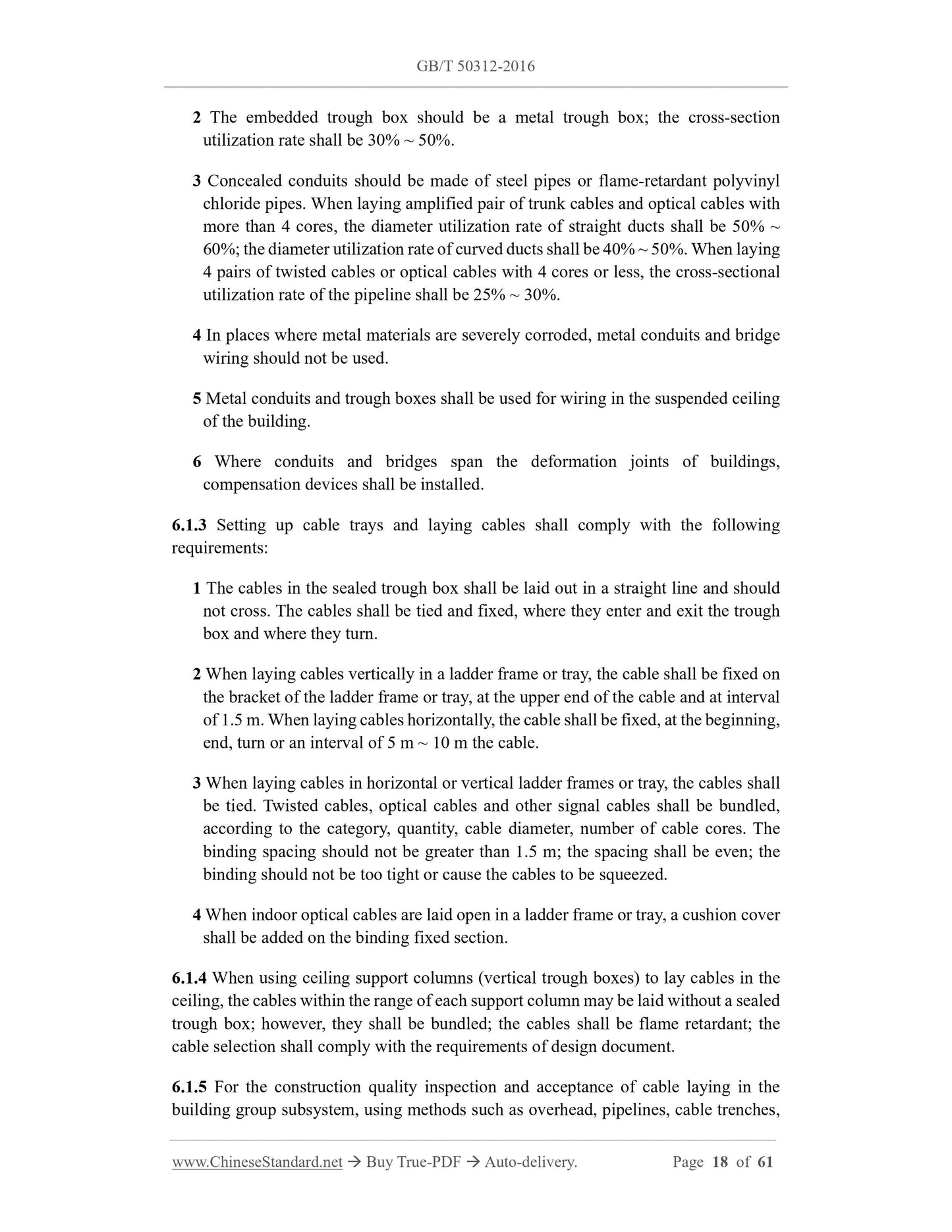
6.1 Cable laying ... 15
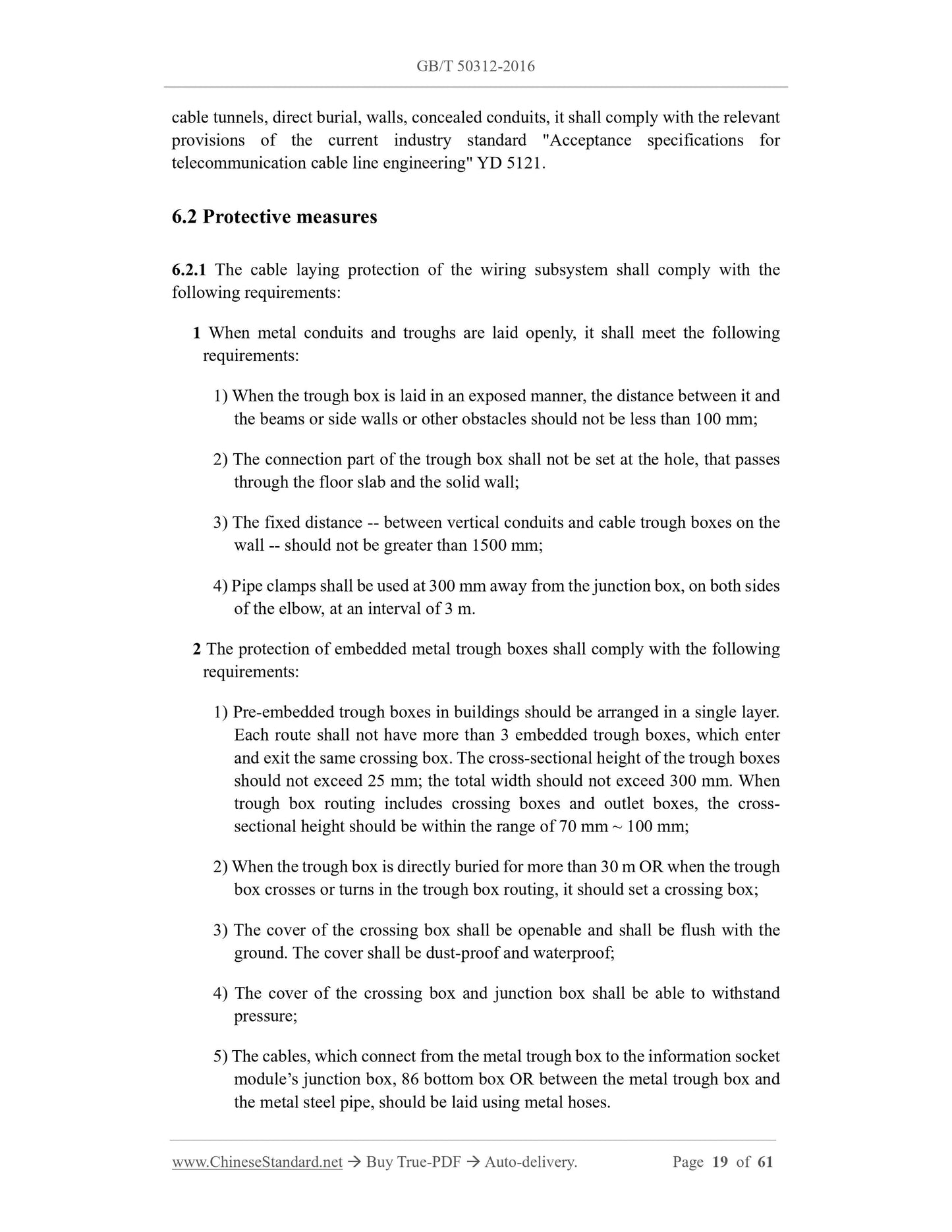
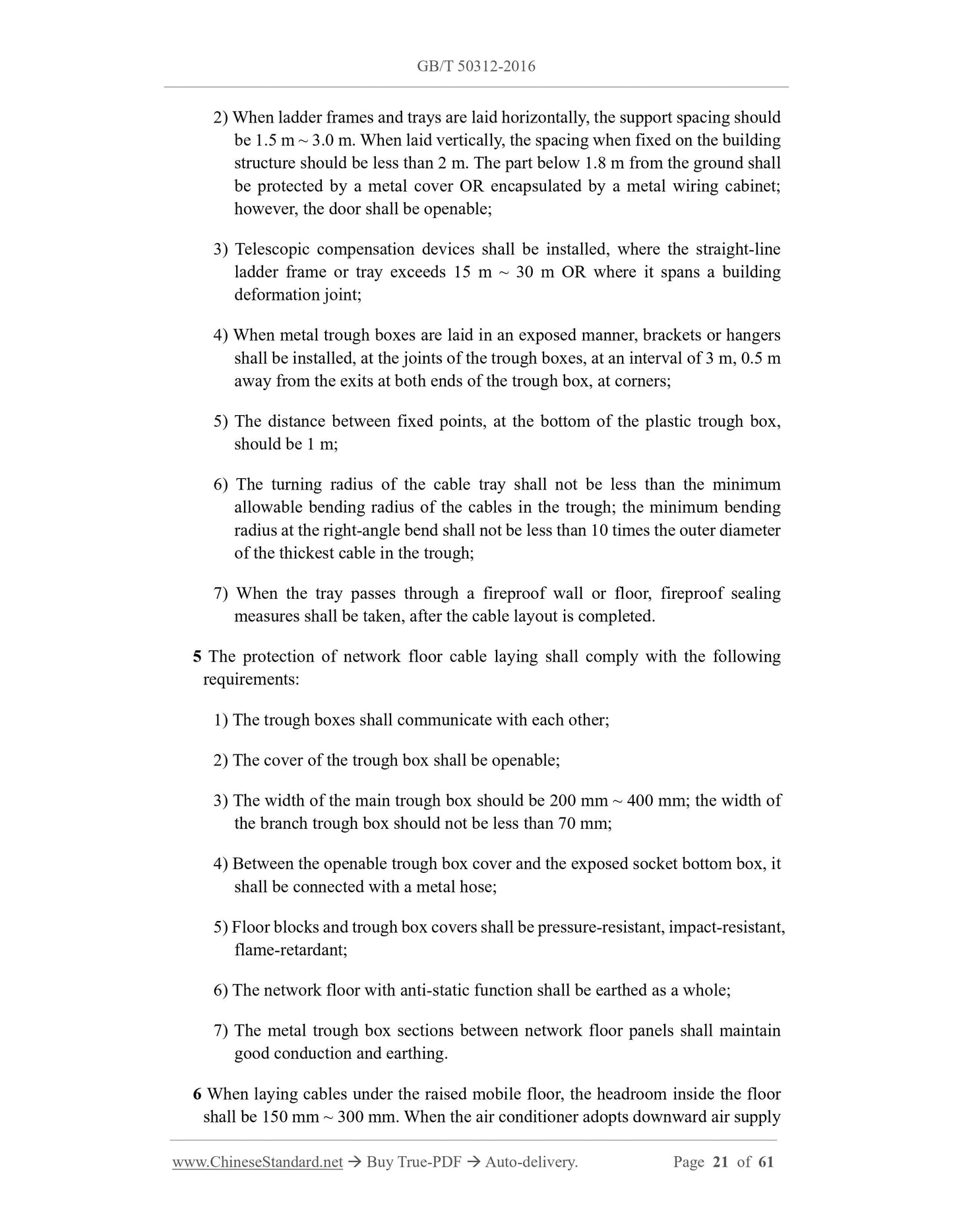
6.2 Protective measures ... 19
7 Cable termination ... 22
8 Engineering electrical testing ... 25
9 Management system acceptance ... 28
10 Engineering acceptance ... 30
Appendix A Engineering inspection contents ... 33
Appendix B Engineering electrical testing methods and contents ... 37
Appendix C Fiber channel and link testing ... 57
Explanation of wording in this code ... 60
List of quoted standards ... 61
Code for engineering acceptance of generic cabling system
1 General provisions
1.0.1 This Code is formulated, to unify the technical requirements for construction
quality inspection, on-site inspection, completion acceptance of generic cabling system
projects for buildings and building complexes.
1.0.2 This Code is applicable to the acceptance of generic cabling system projects for
newly built, expanded, renovated buildings and building complexes.
1.0.3 During the construction process, the construction organization shall comply with
the requirements on construction quality inspection. The building organization shall
strengthen on-site quality inspection, through construction site representatives or
project supervisors; organize the inspection, signoff, certification work of concealed
work in a timely manner.
1.0.4 Self-test and completion acceptance test shall be carried out, before acceptance of
the generic cabling project.
1.0.5 In addition to complying with this Code, the acceptance of generic cabling system
projects shall also comply with the provisions of relevant national standards.
2 Abbreviation
ACR-F: Attenuation to Crosstalk Ratio at the Far-end
ACR-N: Attenuation to Crosstalk Ratio at the Near-end
d.c.: Direct Current Loop Resistance
ELTCTL: Equal Level TCTL
FEXT: Far End Crosstalk Attenuation (loss)
IL: Insertion Loss
NEXT: Near End Crosstalk Attenuation (loss)
OLT: Optical Line Termina1
OLTS: Optical Loss Test Set
OTDR: Optical Time Domain Reflectometer
PS NEXT: Power Sum Near End Crosstalk Attenuation (loss)
PS AACR-F: Power Sum Attenuation to Alien Crosstalk Ratio at the Far-end
PS AACR-Favg: Average Power Sum Attenuation to Alien Crosstalk Ratio at the
Far-end
PS ACR-F: Power Sum Attenuation to Crosstalk Ratio at the Far-end
PS ACR-N: Power Sum Attenuation to Crosstalk Ratio at the Near-end
PS ANEXT: Power Sum Alien Near-End Crosstalk (loss)
PS ANEXTavg: Average Power Sum Alien Near-End Crosstalk (loss)
PS FEXT: Power Sum Far End Crosstalk
RL: Return Loss
TCL: Transverse Conversion Loss
TCTL: Transverse Conversion Transfer Loss
3 Environment examination
3.0.1 The building environment examination of work areas, telecommunications rooms,
equipment rooms, etc. shall comply with the following requirements:
1 The civil works in the work area, telecommunications room, equipment room, user
unit area shall be completed. The floor of the building shall be flat and smooth; the
height and width of the door shall comply with the requirements of design
document.
2 The location, quantity, size of embedded trough boxes, concealed conduits, holes,
shafts in the building shall comply with the requirements of design document.
3 Where the raised floor is laid, the anti-static measures and earthing of the raised
floor shall comply with the requirements of design document.
4 The height -- from the bottom of the information socket box, which is concealed
or exposed on the wall or column to the ground -- should be 300 mm.
5 The height -- from the bottom of the information socket box, which is installed on
the side partition of the workbench to the adjacent wall -- should be 1000 mm.
6 The CP assembly point box and multi-user information socket box should be
installed on the inlet side of the duct, as well as on columns and load-bearing walls,
which are easy for maintenance. The height of the bottom edge of the box, above
the ground, should be 500 mm. When installed on the upper part of the wall or
column OR when installed in a suspended ceiling, the height from the ground
should not be less than 1800 mm.
7 Each work area should be equipped with no less than 2 single-phase AC 220 V/10
A power socket boxes, which have protective earthing. The power socket should
be inlaid and concealed in the wall; the height shall be consistent with the
information socket.
8 It should reserve two single-phase AC 220 V/10 A power sockets, at a level of 70
mm ~ 150 mm near the information distribution box of each user unit. The
distribution lines of each power socket shall be equipped with protective electrical
appliances. The single-phase AC 220 V power supply shall be introduced into the
wiring box. The power socket should be inlaid and concealed in the wall; the height
from the bottom to the ground should be consistent with the information wiring
box.
9 No less than 2 single-phase AC 220 V/10 A power socket boxes shall be installed
in the telecommunications room, equipment room, incoming line room. The
distribution line of each power socket shall be equipped with a protector. The power
supply of the equipment shall be configured separately. The power socket should
be inlaid and concealed in the wall; the height from the bottom to the ground should
be 300 mm.
10 Reliable grounding equipotential bonding terminal boards shall be provided, in
telecommunications rooms, equipment rooms, incoming line rooms, weak current
shafts. The grounding resistance value and grounding wire specifications shall
meet the design requirements.
11 Factors such as the location, area, height, ventilation, fire protection,
environmental temperature, humidity of telecommunications rooms, equipment
rooms, incoming line rooms shall meet the design requirements.
3.0.2 The inspection of the building’s incoming line room and entrance facilities shall
meet the following requirements:
1 The number, combination and arrangement of incoming pipes, as well as the
location and spacing between other facilities, such as electrical, water, gas, sewers,
etc., shall comply with the requirements of the design documents;
2 The laying method used for incoming cables shall comply with the requirements
of the design documents;
3 The treatment of the pipeline inlet shall meet the design requirements; measures
5 Metal pipe troughs shall be galvanized or otherwise anti-corrosion treated,
according to the requirements of the engineering environment. Plastic pipe troughs
shall be flame-retardant pipe troughs; the outer walls shall have flame-retardant
markings;
6 The materials and specifications of various metal parts shall meet the quality
requirements; there shall be no skew, twist, burr, break or damage;
7 The surface treatment and plating of metal parts shall be uniform and complete;
the surface shall be smooth, without defects suc...
Get QUOTATION in 1-minute: Click GB/T 50312-2016
Historical versions: GB/T 50312-2016
Preview True-PDF (Reload/Scroll if blank)
GB/T 50312-2016: Code for engineering acceptance of generic cabling system
GB/T 50312-2016
GB
NATIONAL STANDARD OF THE
PEOPLE’S REPUBLIC OF CHINA
UDC
P GB/T 50312-2016
Code for engineering acceptance of generic cabling system
ISSUED ON: AUGUST 26, 2016
IMPLEMENTED ON: APRIL 01, 2017
Issued by: Ministry of Housing and Urban-Rural Development of PRC.
General Administration of Quality Supervision, Inspection and
Quarantine of PRC.
Table of Contents
Foreword ... 5
1 General provisions ... 7
2 Abbreviation ... 7
3 Environment examination ... 8
4 Examination of equipment and test instrumentation ... 10
5 Examination of equipment installation ... 13
6 Examination of cable laying and protective measures ... 15
6.1 Cable laying ... 15
6.2 Protective measures ... 19
7 Cable termination ... 22
8 Engineering electrical testing ... 25
9 Management system acceptance ... 28
10 Engineering acceptance ... 30
Appendix A Engineering inspection contents ... 33
Appendix B Engineering electrical testing methods and contents ... 37
Appendix C Fiber channel and link testing ... 57
Explanation of wording in this code ... 60
List of quoted standards ... 61
Code for engineering acceptance of generic cabling system
1 General provisions
1.0.1 This Code is formulated, to unify the technical requirements for construction
quality inspection, on-site inspection, completion acceptance of generic cabling system
projects for buildings and building complexes.
1.0.2 This Code is applicable to the acceptance of generic cabling system projects for
newly built, expanded, renovated buildings and building complexes.
1.0.3 During the construction process, the construction organization shall comply with
the requirements on construction quality inspection. The building organization shall
strengthen on-site quality inspection, through construction site representatives or
project supervisors; organize the inspection, signoff, certification work of concealed
work in a timely manner.
1.0.4 Self-test and completion acceptance test shall be carried out, before acceptance of
the generic cabling project.
1.0.5 In addition to complying with this Code, the acceptance of generic cabling system
projects shall also comply with the provisions of relevant national standards.
2 Abbreviation
ACR-F: Attenuation to Crosstalk Ratio at the Far-end
ACR-N: Attenuation to Crosstalk Ratio at the Near-end
d.c.: Direct Current Loop Resistance
ELTCTL: Equal Level TCTL
FEXT: Far End Crosstalk Attenuation (loss)
IL: Insertion Loss
NEXT: Near End Crosstalk Attenuation (loss)
OLT: Optical Line Termina1
OLTS: Optical Loss Test Set
OTDR: Optical Time Domain Reflectometer
PS NEXT: Power Sum Near End Crosstalk Attenuation (loss)
PS AACR-F: Power Sum Attenuation to Alien Crosstalk Ratio at the Far-end
PS AACR-Favg: Average Power Sum Attenuation to Alien Crosstalk Ratio at the
Far-end
PS ACR-F: Power Sum Attenuation to Crosstalk Ratio at the Far-end
PS ACR-N: Power Sum Attenuation to Crosstalk Ratio at the Near-end
PS ANEXT: Power Sum Alien Near-End Crosstalk (loss)
PS ANEXTavg: Average Power Sum Alien Near-End Crosstalk (loss)
PS FEXT: Power Sum Far End Crosstalk
RL: Return Loss
TCL: Transverse Conversion Loss
TCTL: Transverse Conversion Transfer Loss
3 Environment examination
3.0.1 The building environment examination of work areas, telecommunications rooms,
equipment rooms, etc. shall comply with the following requirements:
1 The civil works in the work area, telecommunications room, equipment room, user
unit area shall be completed. The floor of the building shall be flat and smooth; the
height and width of the door shall comply with the requirements of design
document.
2 The location, quantity, size of embedded trough boxes, concealed conduits, holes,
shafts in the building shall comply with the requirements of design document.
3 Where the raised floor is laid, the anti-static measures and earthing of the raised
floor shall comply with the requirements of design document.
4 The height -- from the bottom of the information socket box, which is concealed
or exposed on the wall or column to the ground -- should be 300 mm.
5 The height -- from the bottom of the information socket box, which is installed on
the side partition of the workbench to the adjacent wall -- should be 1000 mm.
6 The CP assembly point box and multi-user information socket box should be
installed on the inlet side of the duct, as well as on columns and load-bearing walls,
which are easy for maintenance. The height of the bottom edge of the box, above
the ground, should be 500 mm. When installed on the upper part of the wall or
column OR when installed in a suspended ceiling, the height from the ground
should not be less than 1800 mm.
7 Each work area should be equipped with no less than 2 single-phase AC 220 V/10
A power socket boxes, which have protective earthing. The power socket should
be inlaid and concealed in the wall; the height shall be consistent with the
information socket.
8 It should reserve two single-phase AC 220 V/10 A power sockets, at a level of 70
mm ~ 150 mm near the information distribution box of each user unit. The
distribution lines of each power socket shall be equipped with protective electrical
appliances. The single-phase AC 220 V power supply shall be introduced into the
wiring box. The power socket should be inlaid and concealed in the wall; the height
from the bottom to the ground should be consistent with the information wiring
box.
9 No less than 2 single-phase AC 220 V/10 A power socket boxes shall be installed
in the telecommunications room, equipment room, incoming line room. The
distribution line of each power socket shall be equipped with a protector. The power
supply of the equipment shall be configured separately. The power socket should
be inlaid and concealed in the wall; the height from the bottom to the ground should
be 300 mm.
10 Reliable grounding equipotential bonding terminal boards shall be provided, in
telecommunications rooms, equipment rooms, incoming line rooms, weak current
shafts. The grounding resistance value and grounding wire specifications shall
meet the design requirements.
11 Factors such as the location, area, height, ventilation, fire protection,
environmental temperature, humidity of telecommunications rooms, equipment
rooms, incoming line rooms shall meet the design requirements.
3.0.2 The inspection of the building’s incoming line room and entrance facilities shall
meet the following requirements:
1 The number, combination and arrangement of incoming pipes, as well as the
location and spacing between other facilities, such as electrical, water, gas, sewers,
etc., shall comply with the requirements of the design documents;
2 The laying method used for incoming cables shall comply with the requirements
of the design documents;
3 The treatment of the pipeline inlet shall meet the design requirements; measures
5 Metal pipe troughs shall be galvanized or otherwise anti-corrosion treated,
according to the requirements of the engineering environment. Plastic pipe troughs
shall be flame-retardant pipe troughs; the outer walls shall have flame-retardant
markings;
6 The materials and specifications of various metal parts shall meet the quality
requirements; there shall be no skew, twist, burr, break or damage;
7 The surface treatment and plating of metal parts shall be uniform and complete;
the surface shall be smooth, without defects suc...
Share