1
/
of
5
www.ChineseStandard.us -- Field Test Asia Pte. Ltd.
GB/T 5334-2021 English PDF (GB/T5334-2021)
GB/T 5334-2021 English PDF (GB/T5334-2021)
Regular price
$185.00
Regular price
Sale price
$185.00
Unit price
/
per
Shipping calculated at checkout.
Couldn't load pickup availability
GB/T 5334-2021: Passenger car - Wheels - Performance requirements and test methods for cornering and radial fatigue
Delivery: 9 seconds. Download (& Email) true-PDF + Invoice.
Get Quotation: Click GB/T 5334-2021 (Self-service in 1-minute)
Historical versions (Master-website): GB/T 5334-2021
Preview True-PDF (Reload/Scroll-down if blank)
GB/T 5354-2021
GB
NATIONAL STANDARD OF THE
PEOPLE’S REPUBLIC OF CHINA
ICS 43.040.50
CCS T 22
GB/T 5334-2021
Replacing GB/T 5334-2005
Passenger Car - Wheels - Performance Requirements
and Test Methods for Cornering and Radial Fatigue
(ISO 3006:2015, Road Vehicles – Passenger
Car Wheels for Road Use – Test Methods, MOD)
ISSUED ON: OCTOBER 11, 2021
IMPLEMENTED ON: MAY 01, 2022
Issued by: State Administration for Market Regulation;
Standardization Administration of PRC.
Table of Contents
Foreword ... 3
1 Scope ... 6
2 Normative References ... 6
3 Terms and Definitions ... 6
4 Test Wheels ... 7
5 Performance Requirements ... 7
5.1 Requirements of dynamic bending fatigue test performance ... 7
5.2 Requirements of dynamic radial fatigue test performance ... 7
6 Test Methods ... 8
6.1 Dynamic bending fatigue test ... 8
6.2 Dynamic radial fatigue test ... 10
Appendix A (Informative) Structural Changes from this Document to ISO
3006:2015 ... 13
Bibliography ... 14
Passenger Car - Wheels - Performance Requirements
and Test Methods for Cornering and Radial Fatigue
1 Scope
This Document specifies the test wheels, performance requirements and test methods
for the dynamic bending fatigue test and dynamic radial fatigue test of passenger car
wheels.
This Document applies to the wheels used by passenger cars specified in GB/T 3730.1.
2 Normative References
The provisions in following documents become the provisions of this Document
through reference in this Document. For the dated documents, only the versions with
the dates indicated are applicable to this Document; for the undated documents, only
the latest version (including all the amendments) is applicable to this Document.
GB/T 2933 Wheels and Rims for Pneumatic Tyres - Vocabulary, Designation and
Marking (GB/T 2933-2009, ISO 3911:2004, IDT)
GB/T 3730.1 Motor Vehicles and Trailers – Types - Terms and Definitions (GB/T
3730.1-2001, ISO 3833:1999, MOD)
3 Terms and Definitions
For the purposes of this Document, the terms and definitions given in GB/T 2933 and
GB/T 3730.1 and the following apply.
3.1 Wheel-tire assembly
An assembly that is made up of wheels, tires and valves.
3.2 Crack
The material separation which, during the test, is enlarged to 3mm and above.
d - wheel internal offset or external offset (internal offset is a positive value, and
external offset is a negative value), in m;
Fv - the maximum vertical static load of the wheel or the rated load of the wheel
specified by the vehicle or wheel manufacturer, in N;
S – strengthening coefficient, see Table 1.
6.1.3 Test procedures
6.1.3.1 Refer to Figure 1 to clamp the wheel to the test equipment. Tighten the wheel
tightening bolts (or nuts) to the torque value specified by the vehicle or wheel
manufacturer. If not specified, the tightening torque shall be set to (120±10) N • m.
6.1.3.2 Set the test parameters such as bending moment, speed and number of cycles,
and start the test. In the initial stage of the test, the machine can be shut down to
tighten the tightening bolts or nuts of the wheels again. If the bolt breaks during the
test, continue the test after replacing all the bolts.
6.1.3.3 After completing the specified number of test cycles, stop the machine; and use
penetrant testing or other acceptable methods to check for wheel cracks.
6.1.4 Failure criteria
In any of the following situations, the test is terminated and the wheel fails:
a) The wheel cannot continue to bear the test load;
b) The original cracks have expanded, or the stress has caused new cracks to
invade the wheel section;
c) The offset increment of the loading point exceeds 10% of the initial offset of the
test.
6.2 Dynamic radial fatigue test
6.2.1 Test equipment
The test equipment shall have a driven drum and wheel mounts to rotate the wheel-
tire assembly under a fixed radial force, as shown in Figure 2. The minimum diameter
of the drum is 1700mm, the width shall be wider than the cross section of the tire, and
the surface shall be smooth. The connecting surface of the wheel mount shall have the
same assembling dimensional characteristics as the connecting parts usually used on
the vehicle. The surface hardness is recommended to be HRC40~HRC50; and the
position of the screw holes or bolts on the distribution circle of the connecting surface
shall be controlled within ϕ0.10mm.
The loading system shall maintain the specified load, and the deviation shall not
6.2.2.3 Determination of radial load
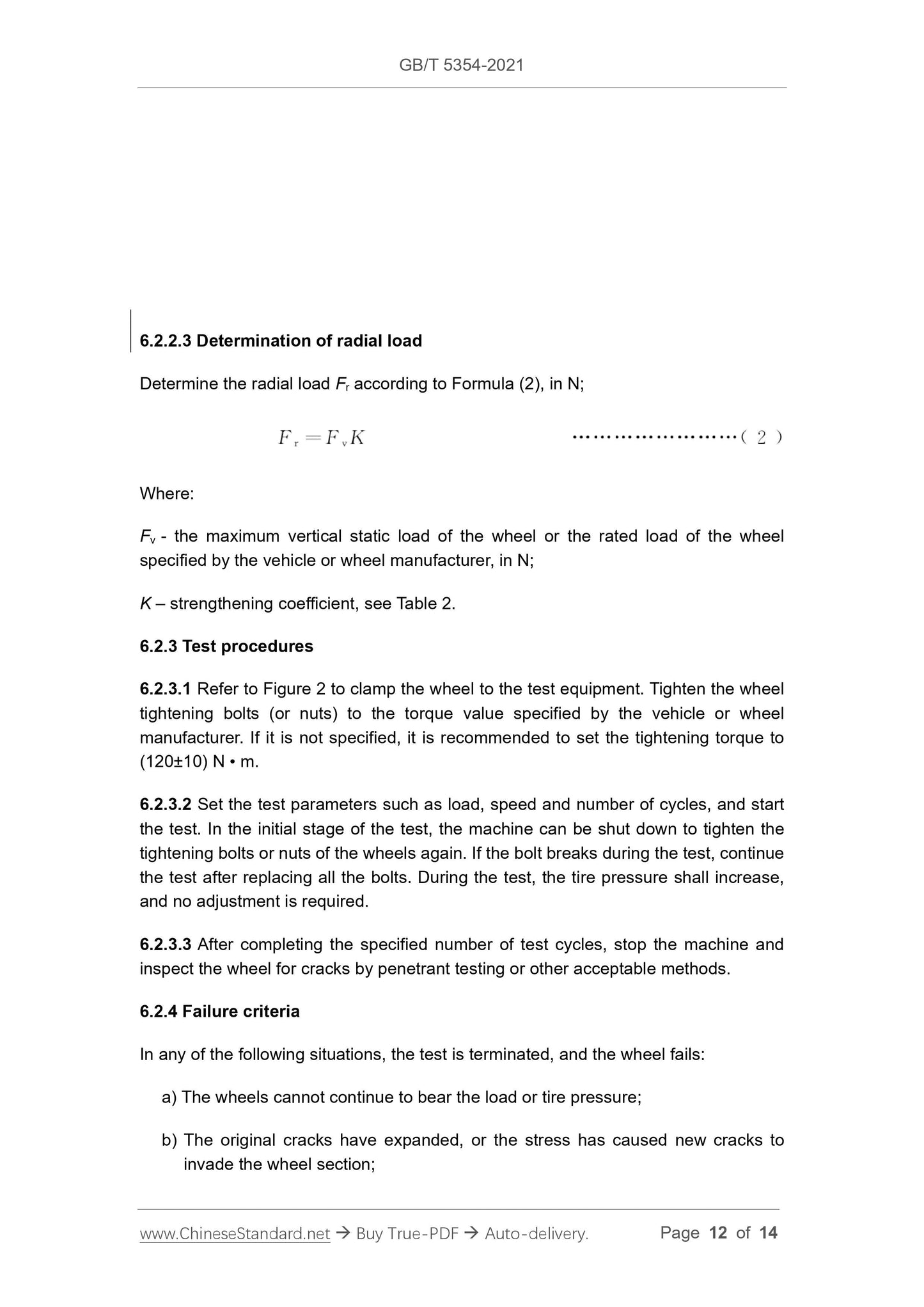
Determine the radial load Fr according to Formula (2), in N;
Where:
Fv - the maximum vertical static load of the wheel or the rated load of the wheel
specified by the vehicle or wheel manufacturer, in N;
K – strengthening coefficient, see Table 2.
6.2.3 Test procedures
6.2.3.1 Refer to Figure 2 to clamp the wheel to the test equipment. Tighten the wheel
tightening bolts (or nuts) to the torque value specified by the vehicle or wheel
manufacturer. If it is not specified, it is recommended to set the tightening torque to
(120±10) N • m.
6.2.3.2 Set the test parameters such as load, speed and number of cycles, and start
the test. In the initial stage of the test, the machine can be shut down to tighten the
tightening bolts or nuts of the wheels again. If the bolt breaks during the test, continue
the test after replacing all the bolts. During the test, the tire pressure shall increase,
and no adjustment is required.
6.2.3.3 After completing the specified number of test cycles, stop the machine and
inspect the wheel for cracks by penetrant testing or other acceptable methods.
6.2.4 Failure criteria
In any of the following situations, the test is terminated, and the wheel fails:
a) The wheels cannot continue to bear the load or tire pressure;
b) The original cracks have expanded, or the stress has caused new cracks to
invade the wheel section;
Share
