1
/
of
8
PayPal, credit cards. Download editable-PDF and invoice in 1 second!
GB/T 5764-2023 English PDF (GBT5764-2023)
GB/T 5764-2023 English PDF (GBT5764-2023)
Regular price
$260.00 USD
Regular price
Sale price
$260.00 USD
Unit price
/
per
Shipping calculated at checkout.
Couldn't load pickup availability
Delivery: 3 seconds. Download true-PDF + Invoice.
Get QUOTATION in 1-minute: Click GB/T 5764-2023
Historical versions: GB/T 5764-2023
Preview True-PDF (Reload/Scroll if blank)
GB/T 5764-2023: Clutch facings for automobiles
GB/T 5764-2023
GB
NATIONAL STANDARD OF THE
PEOPLE’S REPUBLIC OF CHINA
ICS 43.040.40
CCS Q 69
Replacing GB/T 5764-2011
Clutch Facings for Automobiles
ISSUED ON: DECEMBER 28, 2023
IMPLEMENTED ON: JULY 01, 2024
Issued by: State Administration for Market Regulation;
Standardization Administration of the People’s Republic of China.
Table of Contents
Foreword ... 3
1 Scope ... 5
2 Normative References ... 5
3 Terms and Definitions ... 5
4 Requirements ... 6
5 Test Methods ... 8
6 Inspection Rules ... 15
7 Marking, Packaging, Transportation and Storage ... 17
Appendix A (Informative) Recommendation List on Basic Dimension of Facing
... 18
Appendix B (Normative) Fixture for Bending Test ... 19
Clutch Facings for Automobiles
1 Scope
This Document specifies the requirements, test methods, inspection rules, marking, packaging,
transportation and storage of clutch facings for automobiles.
This Document is applicable to winding dry friction clutch facings for automobiles (hereinafter
referred to as "facings").
2 Normative References
The provisions in following documents become the essential provisions of this Document
through reference in this Document. For the dated documents, only the versions with the dates
indicated are applicable to this Document; for the undated documents, only the latest version
(including all the amendments) is applicable to this Document.
GB/T 2828.1 Sampling procedures for inspection by attribute - Part1: Sampling schemes
indexed by acceptance quality limit (AQL) for lot-by-lot inspection
GB 5763 Brake linings for automobiles
GB/T 23263 Determination of asbestos in products
GB/T 26125 Electrical and electronic products - Determination of six regulated substances
(lead, mercury, cadmium, hexavalent chromium, polybrominated biphenyls,
polybrominated diphenyl ethers)
JB/T 7498 Coated abrasives - Abrasive paper
JC/T 1065 Constant speed friction test machine
JC/T 2268 Measurement of copper and other elements in brake friction materials
3 Terms and Definitions
For the purposes of this Document, the terms and definitions given in GB 5763 and the
following apply.
3.1 Max flexibility; δ
During the bending test, the distance of the top or bottom surface of the span center of the test
protrusions on both sides.
5.3.2 Test equipment
5.3.2.1 Standard flat plate: accuracy level is Level-2 or above.
5.3.2.2 Preloading fixture: In the circular ring shape; the mass shall meet the specified load in
Table 2; the error shall be no greater than ±1%; and the flatness shall be less than 0.05mm.
5.3.2.3 Feeler gauge: The accuracy is no less than 0.01mm.
5.3.3 Test procedures
5.3.3.1 Place the facing flat on the standard flat plate with the working surface downward. No
part of the facing shall exceed the outer edge of the standard flat plate.
5.3.3.2 Select the appropriate preloading fixture according to the size of the facing. Place the
preloading fixture flat on the facing to be tested; and ensure that any part of the facing is
completely covered by the fixture and it is concentric with the facing. Use a feeler gauge to
check the gap between the working surface of the facing and the flat plate. It is required to
measure 6 points on the inner hole and the outer circle at 60° intervals along the circumference.
5.3.4 Expression of results
Take the maximum value among the 12 measured gaps as the flatness value of the facing.
5.4 Friction property
5.4.1 Test pieces
5.4.1.1 Two test pieces are made from the same facing.
5.4.1.2 The size of the test piece is 25mm×25mm; and the allowable deviation is ±0.2mm.
5.4.1.3 The thickness of the test piece is that of the facing; and the thickness difference between
the two test pieces is less than 0.2mm.
5.4.2 Test equipment
5.4.2.1 Fixed-speed friction testing machine: Its performance and accuracy shall comply with
the provisions of JC/T 1065.
5.4.2.2 Micrometer: The accuracy is no less than 0.01mm.
5.4.3 Test conditions
5.4.3.1 The pressure of the test piece is 0.49MPa.
5.4.3.2 The disc material shall comply with the provisions of JC/T 1065. The surface shall be
treated by sandpaper with grain size of P240 specified in JB/T 7498; so that there are no obvious
scratches, rust, pits and other defects on the surface of the disc.
5.4.3.3 The rubbing direction is the same as that of the facing.
5.4.4 Test procedures
5.4.4.1 Put the two test pieces into the test piece support arm and run them in at 100 ℃ and
below until the contact surface reaches more than 95%. Use a micrometer with an accuracy of
no less than 0.01mm to measure the thickness of the test piece. The thickness measurement
shall be carried out after the test piece has cooled to room temperature. Measure 5 points on
each test piece and take the arithmetic mean value.
5.4.4.2 At the test temperature of 100°C, measure the friction force during the disc rotation of
5000r. After the friction test, measure the thickness of the test piece according to the
requirements of 5.4.4.1.
5.4.4.3 At each test temperature of 150°C, 200°C, 250°C, and 300°C, conduct the same test
according to the requirements of 5.4.4.2. The maximum test temperature of various types of
facings shall comply with the provisions of Table 3. During each temperature test, the disc
temperature shall rise to the specified test temperature within 1500r. When the disc temperature
cannot reach the specified test temperature within 1500r, the auxiliary heating device shall be
used.
5.4.4.4 After the maximum test temperature measurement is completed, measure the friction
force during the disc rotation of 3000r at 100°C.
5.4.4.5 After the test, the appearance of the friction surface of the test piece and disc shall be
inspected visually.
5.4.5 Calculation
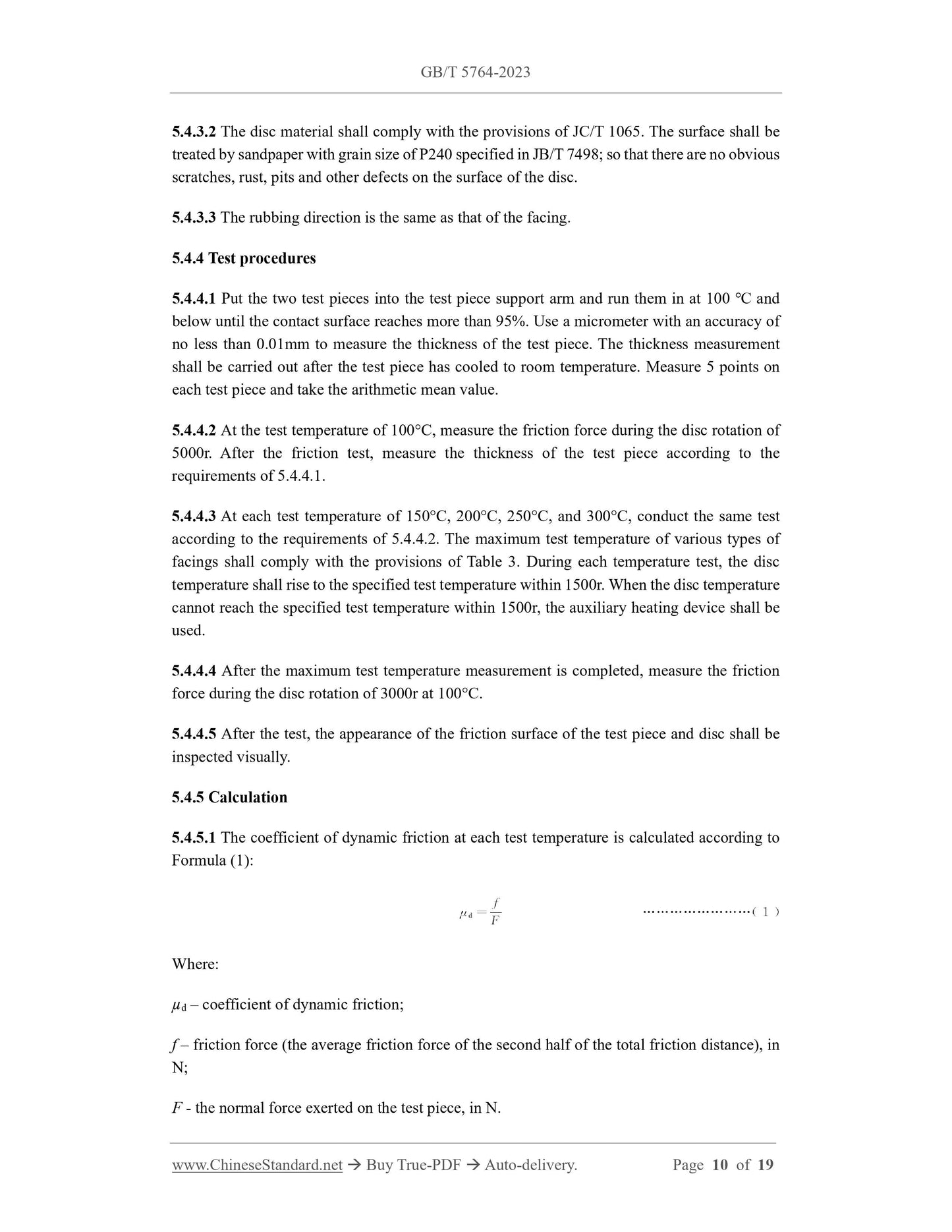
5.4.5.1 The coefficient of dynamic friction at each test temperature is calculated according to
Formula (1):
Where:
µd – coefficient of dynamic friction;
f – friction force (the average friction force of the second half of the total friction distance), in
N;
F - the normal force exerted on the test piece, in N.
5.5.2.4 Micrometer: With accuracy no less than 0.01mm.
5.5.2.5 Vernier caliper: With accuracy no less than 0.02mm.
5.5.3 Test procedures
5.5.3.1 The thickness of the test piece shall be measured by a micrometer at three points in the
middle; and the arithmetic mean value shall be taken. The width of the test piece shall be
measured by a vernier caliper at three points in the middle; and the arithmetic mean value shall
be taken.
5.5.3.2 Adjust the distance between the fulcrums according to the test piece.
5.5.3.3 Place the test piece on the fulcrum of the test fixture with the friction surface side facing
up.
5.5.3.4 Start the testing machine to apply load, and measure the maximum load at the moment
when the test piece breaks and the max. flexibility at the time of failure.
5.5.4 Calculation
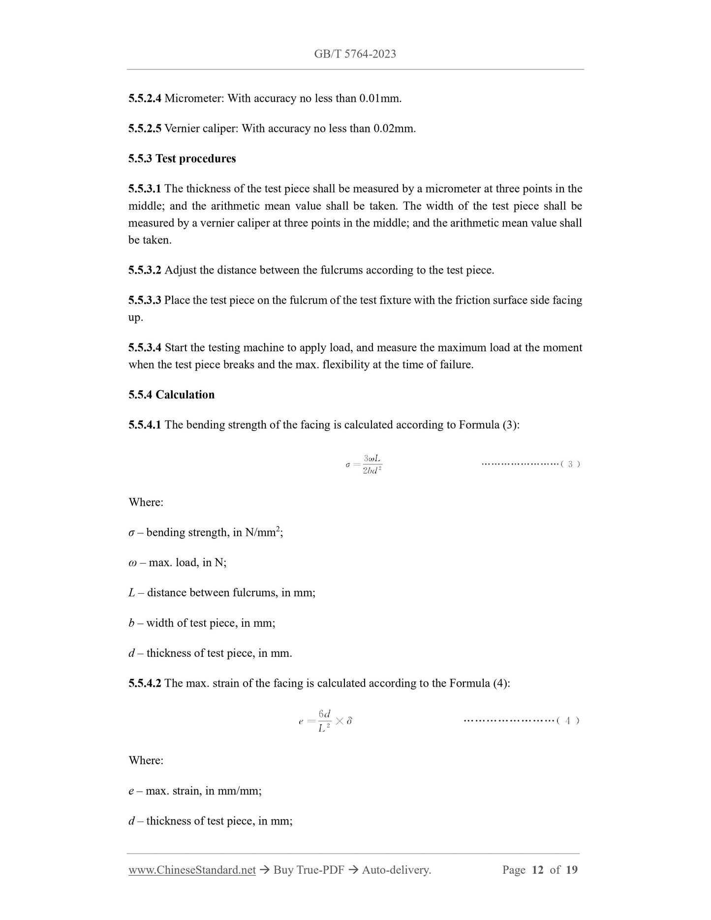
5.5.4.1 The bending strength of the facing is calculated according to Formula (3):
Where:
σ – bending strength, in N/mm2;
ω – max. load, in N;
L – distance between fulcrums, in mm;
b – width of test piece, in mm;
d – thickness of test piece, in mm.
5.5.4.2 The max. strain of the facing is calculated according to the Formula (4):
Where:
e – max. strain, in mm/mm;
d – thickness of test piece, in mm;
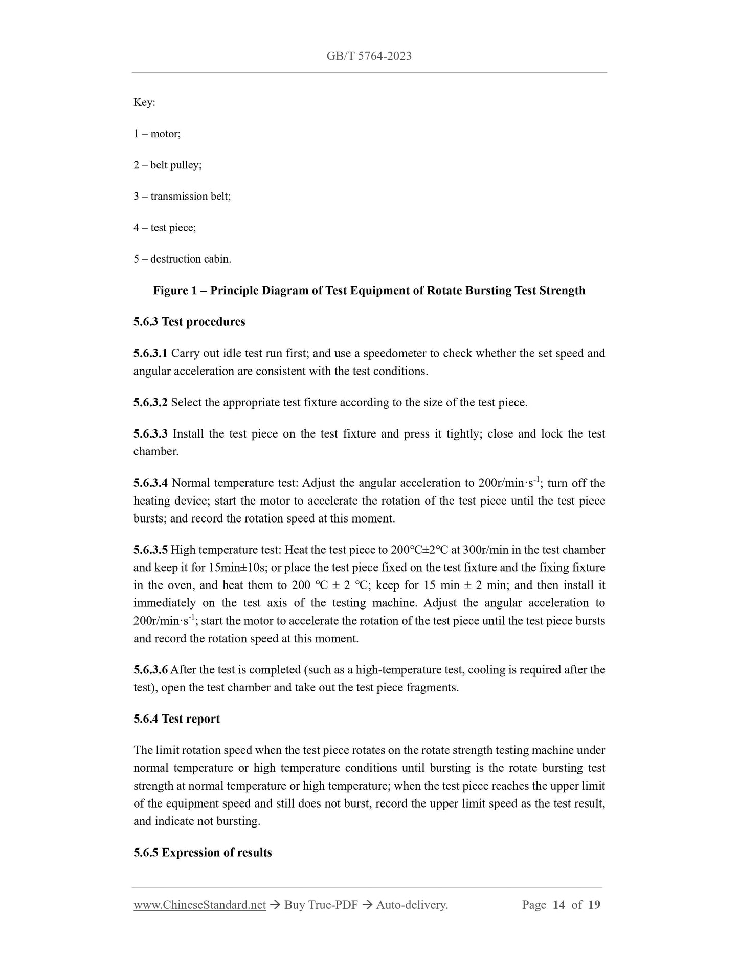
Key:
1 – motor;
2 – belt pulley;
3 – transmission belt;
4 – test piece;
5 – destruction cabin. <...
Share
