1
/
of
12
www.ChineseStandard.us -- Field Test Asia Pte. Ltd.
JJG 162-2019 English PDF
JJG 162-2019 English PDF
Regular price
$500.00
Regular price
Sale price
$500.00
Unit price
/
per
Shipping calculated at checkout.
Couldn't load pickup availability
JJG 162-2019: Cold Potable Water Meters
Delivery: 9 seconds. Download (& Email) true-PDF + Invoice.
Get Quotation: Click JJG 162-2019 (Self-service in 1-minute)
Historical versions (Master-website): JJG 162-2019
Preview True-PDF (Reload/Scroll-down if blank)
JJG 162-2019
JJG
METROLOGICAL VERIFICATION REGULATION
OF THE PEOPLE’S REPUBLIC OF CHINA
Cold portable water meters
ISSUED ON: DECEMBER 31, 2019
IMPLEMENTED ON: MARCH 31, 2020
Issued by: General Administration of Quality Supervision, Inspection and
Quarantine of PRC.
Table of Contents
Introduction ... 4
1 Scope ... 6
2 Normative references ... 6
3 Terms and units of measurement ... 6
3.1 Terms ... 6
3.2 Units of measurement ... 12
4 Overview ... 12
4.1 Principle and structural composition ... 12
4.2 Classification ... 13
5 Metering performance requirements ... 14
5.1 Flow characteristics of water meters ... 14
5.2 Accuracy level and maximum allowable error ... 15
6 General technical requirements ... 15
6.1 Appearance, sign, seal ... 15
6.2 Functions of electronic devices ... 18
6.3 Tightness ... 19
7 Measuring instrument control ... 19
7.1 Verification conditions ... 19
7.2 Verification items ... 22
7.3 Verification method ... 22
7.4 Handling of verification results ... 33
7.5 Verification cycle ... 34
Appendix A Methods for in-use inspection of water meter ... 35
Appendix B Reference format of verification records ... 38
Appendix C Format of the inner pages of the verification certificate and verification
result notification ... 41
Appendix D Classification of water meters ... 42
Appendix E Density lookup table method ... 47
Verification regulation of cold portable water meters
1 Scope
This Regulation applies to the initial verification, subsequent verification, in-use
inspection of cold portable water meters.
The cold portable water meter referred to in this Regulation is a water meter, which has
a temperature grade T30 and T50, measures cold portable water flowing through a
closed full pipe, including water meters whose working principle is based on
mechanical principle, water meters whose working principle is based on electronic or
electromagnetic principle, water meters based on mechanical principle with electronic
device.
2 Normative references
This Regulation makes reference to the following documents:
JJG 164 Verification regulation of standard facilities for liquid flowrate
JJG 643 Verification regulation of flow standard facilities by master meter method
JJG 1113 Verification regulation of verification facility for water meters
JJF 1777-2019 Program of pattern evaluation of cold potable water meters
For any dated references, only the dated version applies to this Regulation; for any
undated referenced document, its latest version (including all amendments) applies to
this Regulation.
3 Terms and units of measurement
3.1 Terms
3.1.1 Water meter
Under measurement conditions, an instrument used to continuously measure, record,
and display the volume of water flowing through the measurement transducer.
Note: The water meter includes at least one measurement transducer, a calculator (including
adjustment or correction device if any), and an indicating device. The three can be placed
An indication value controlled by legal metrology.
Note: If there is a repeated indication, the initial indication of the measurement result is the
primary indication.
3.1.13 Permanent flow rate (Q3)
The maximum flow rate under rated working conditions. At this flow rate, the water
meter shall work normally and meet the maximum allowable error requirements.
Note: In this Regulation, this flow rate is expressed in m3/h.
3.1.14 Overload flow rate (Q4)
The maximum flow rate that requires the water meter to meet the maximum
allowable error requirements in a short period of time and then maintain the metering
characteristics under rated working conditions.
Note: The reference definition of "short period of time" here is "no more than 1 h in a day
and no more than 200 h in a year".
3.1.15 Minimum flow rate (Q1)
The minimum flow rate that requires the water meter to work within the maximum
allowable error.
3.1.16 Transitional flow rate (Q2)
The flow rate that appears between the common flow rate and the minimum flow
rate, dividing the flow range into two zones: "high flow zone" and "low flow zone",
each with a specific maximum allowable error.
Note: Q1 ≤ Q < Q2 is usually called "low flow zone"; Q2 ≤ Q ≤ Q4 is called "high flow zone".
3.1.17 Combination meter changeover flow rate (Qx)
The flow rate Qx1 when the large water meter stops working as the flow rate
decreases, or the flow rate Qx2 when the large water meter starts working as the flow
rate increases.
Note: For the structural features of combination water meters, see D.2.2.5 in Appendix D.
3.1.18 Maximum allowable (working) pressure (MAP)
The maximum internal pressure, that the water meter can withstand under rated
working conditions without deteriorating the metering characteristics.
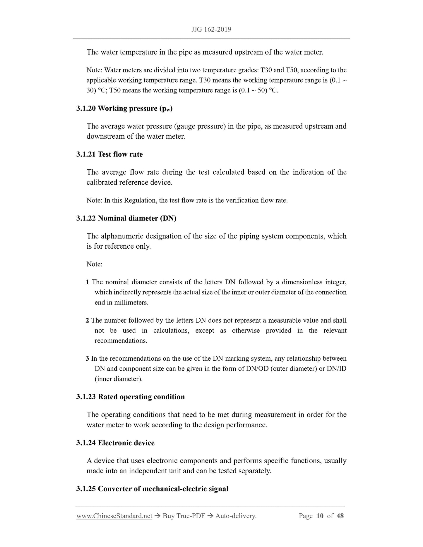
3.1.19 Working temperature (Tw)
The water temperature in the pipe as measured upstream of the water meter.
Note: Water meters are divided into two temperature grades: T30 and T50, according to the
applicable working temperature range. T30 means the working temperature range is (0.1 ~
30) °C; T50 means the working temperature range is (0.1 ~ 50) °C.
3.1.20 Working pressure (pw)
The average water pressure (gauge pressure) in the pipe, as measured upstream and
downstream of the water meter.
3.1.21 Test flow rate
The average flow rate during the test calculated based on the indication of the
calibrated reference device.
Note: In this Regulation, the test flow rate is the verification flow rate.
3.1.22 Nominal diameter (DN)
The alphanumeric designation of the size of the piping system components, which
is for reference only.
Note:
1 The nominal diameter consists of the letters DN followed by a dimensionless integer,
which indirectly represents the actual size of the inner or outer diameter of the connection
end in millimeters.
2 The number followed by the letters DN does not represent a measurable value and shall
not be used in calculations, except as otherwise provided in the relevant
recommendations.
3 In the recommendations on the use of the DN marking system, any relationship between
DN and component size can be given in the form of DN/OD (outer diameter) or DN/ID
(inner diameter).
3.1.23 Rated operating condition
The operating conditions that need to be met during measurement in order for the
water meter to work according to the design performance.
3.1.24 Electronic device
A device that uses electronic components and performs specific functions, usually
made into an independent unit and can be tested separately.
3.1.25 Converter of mechanical-electric signal
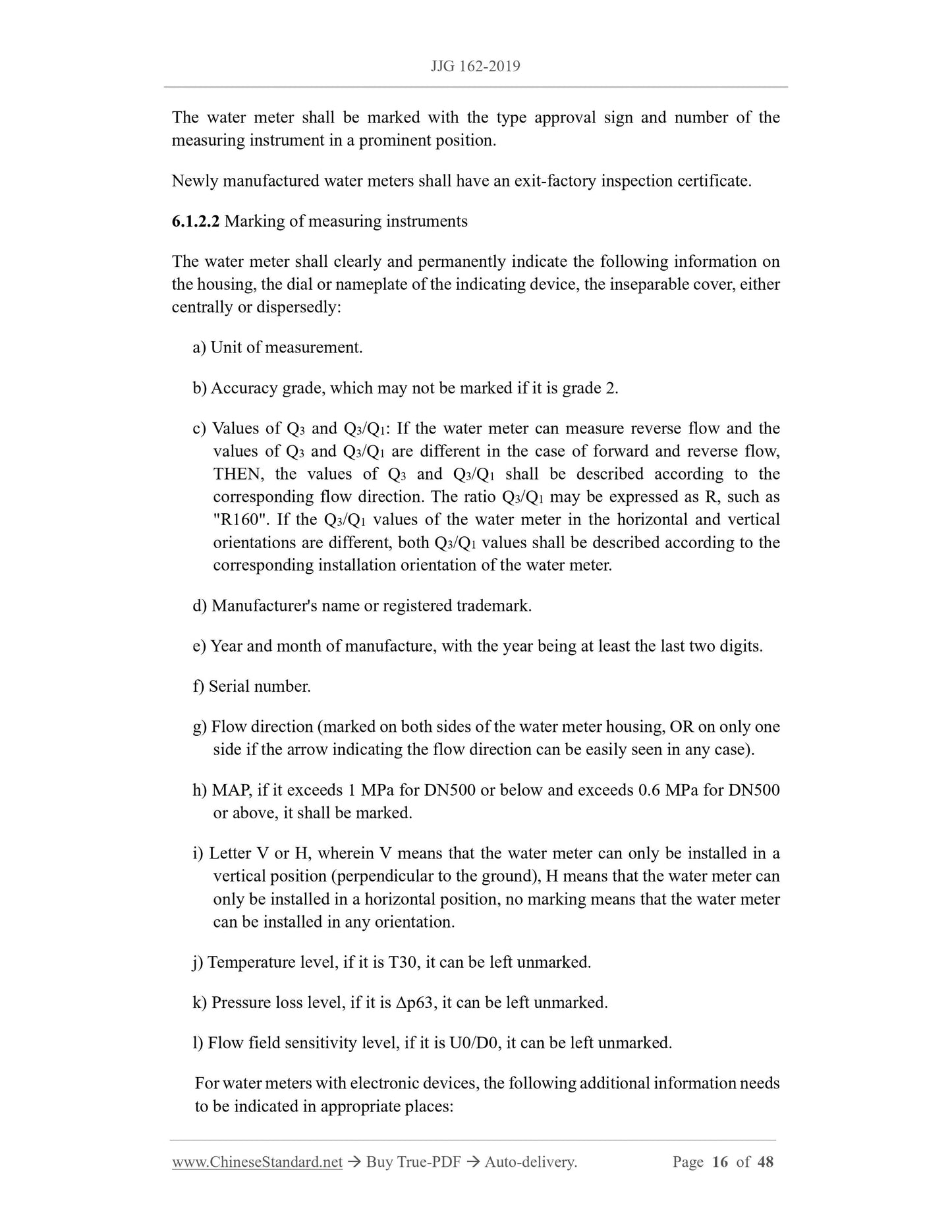
The water meter shall be marked with the type approval sign and number of the
measuring instrument in a prominent position.
Newly manufactured water meters shall have an exit-factory inspection certificate.
6.1.2.2 Marking of measuring instruments
The water meter shall clearly and permanently indicate the following information on
the housing, the dial or nameplate of the indicating device, the inseparable cover, either
centrally or dispersedly:
a) Unit of measurement.
b) Accuracy grade, which may not be marked if it is grade 2.
c) Values of Q3 and Q3/Q1: If the water meter can measure reverse flow and the
values of Q3 and Q3/Q1 are different in the case of forward and reverse flow,
THEN, the values of Q3 and Q3/Q1 shall be described according to the
corresponding flow direction. The ratio Q3/Q1 may be expressed as R, such as
"R160". If the Q3/Q1 values of the water meter in the horizontal and vertical
orientations are different, both Q3/Q1 values shall be described according to the
corresponding installation orientation of the water meter.
d) Manufacturer's name or registered trademark.
e) Year and month of manufacture, with the year being at least the last two digits.
f) Serial number.
g) Flow direction (marked on both sides of the water meter housing, OR on only one
side if the arrow indicating the flow direction can be easily seen in any case).
h) MAP, if it exceeds 1 MPa for DN500 or below and exceeds 0.6 MPa for DN500
or above, it shall be marked.
i) Letter V or H, wherein V means that the water meter can only be installed in a
vertical position (perpendicular to the ground), H means that the water meter can
only be installed in a horizontal position, no marking means that the water meter
can be installed in any orientation.
j) Temperature level, if it is T30, it can be left unmarked.
k) Pressure loss level, if it is Δp63, it can be left unmarked.
l) Flow field sensitivity level, if it is U0/D0, it can be left unmarked.
For water meters with electronic devices, the following additional information needs
to be indicated in appropriate places:
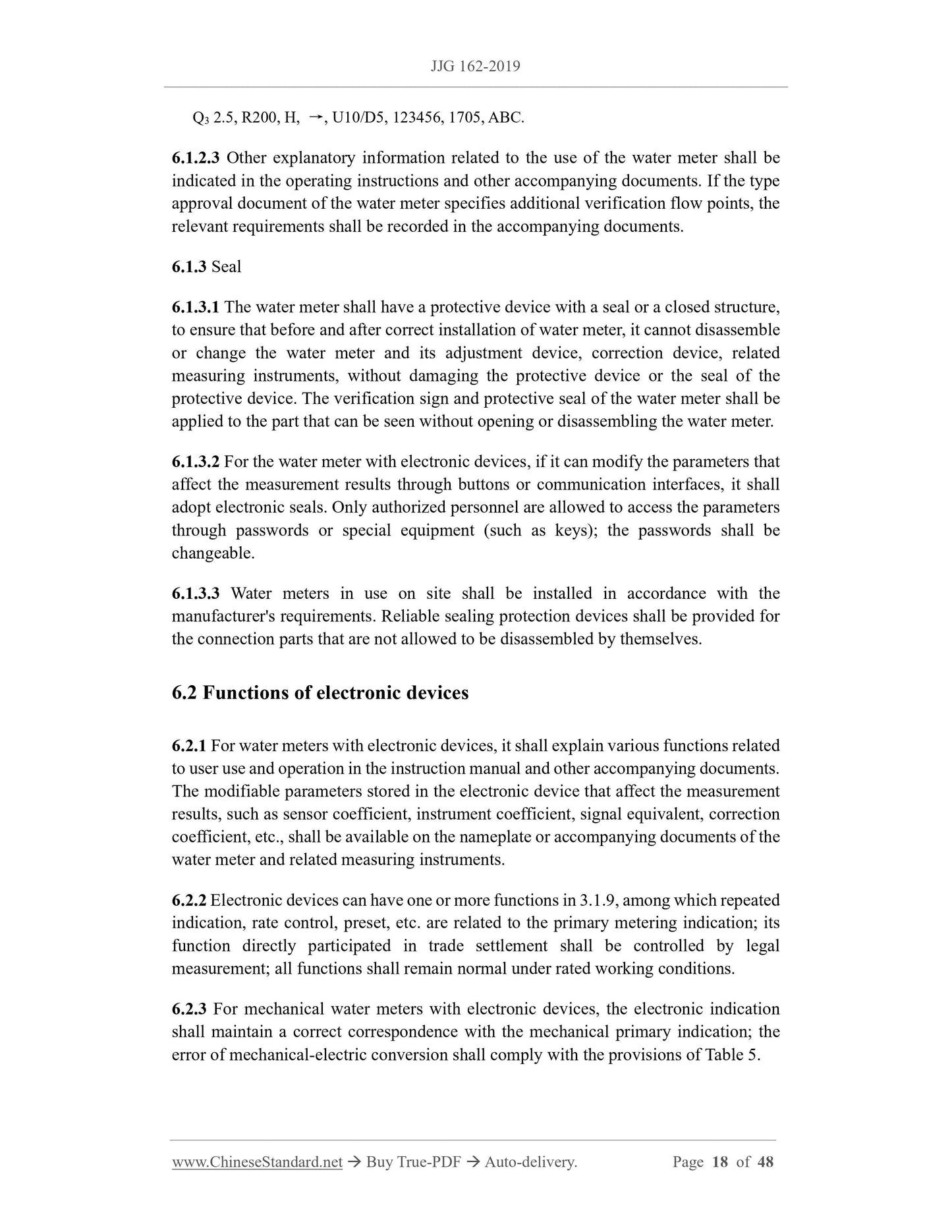
Q3 2.5, R200, H, →, U10/D5, 123456, 1705, ABC.
6.1.2.3 Other explanatory information related to the use of the water meter shall be
indicated in the operating instructions and other accompanying documents. If the type
approval document of the water meter specifies additional verification flow points, the
relevant requirements shall be recorded in the accompanying documents.
6.1.3 Seal
6.1.3.1 The water meter shall have a protective device with a seal or a closed structure,
to ensure that before and after correct installation of water meter, it cannot disassemble
or change the water meter and its adjustment device, correction device, related
measuring instruments, without damaging the protective device or the seal of the
protective device. The verification sign and protective seal of the water meter shall be
applied to the part that can be seen without opening or disassembling the water meter.
6.1.3.2 For the water meter with electronic devices, if it can modify the parameters that
affect the measurement results through buttons or communication interfaces, it shall
adopt electronic seals. Only authorized personnel are allowed to access the parameters
through passwords or special equipment (such as keys); the passwords shall be
changeable.
6.1.3.3 Water meters in use on site shall be installed in accordance with the
manufacturer's requirements. Reliable sealing protection devices shall be provided for
the connection parts that are not allowed to be disassembled by themselves.
6.2 Functions of electronic devices
6.2.1 For water meters with electronic devices, it shall explain various functions related
to user use and operation in the instruction manual and other accompanying documents.
The modifiable parameters stored in the electronic device that affect the measurement
results, such as sensor coefficient, instrument coefficient, signal equivalent, correction
coefficient, etc., shall be available on the nameplate or accompanying documents of the
water meter and related measuring instruments.
6.2.2 Electronic devices can have one or more functions in 3.1.9, among which repeated
indication, rate control, preset, etc. are related to the primary metering indication; its
function directly participated in trade settlement shall be controlled by legal
measurement; all functions shall remain normal under rated working conditions.
6.2.3 For mechanical water meters with electronic devices, the electronic indication
shall maintain a correct correspondence with the mechanical primary indication; the
error of mechanical-electric conversion shall comply with the provisions of Table 5.
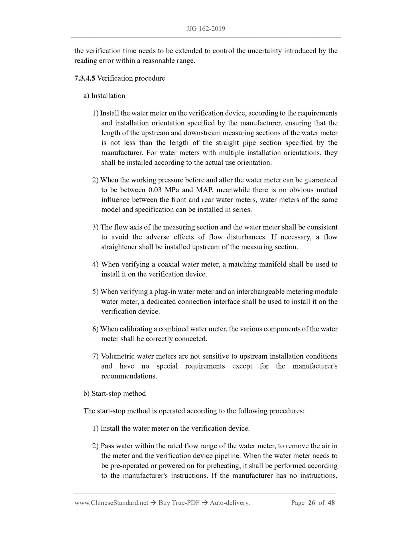
the verification time needs to be extended to control the uncertainty introduced by the
reading error within a reasonable range.
7.3.4.5 Verification procedure
a) Installation
1) Install the water meter on the verification device, according to the requirements
and installation orientation specified by the manufacturer, ensuring that the
length of the upstream and downstream measuring sections of the water meter
is not less than the length of the straight pipe section specified by the
manufacturer. For water meters with multiple installation orientations, they
shall be installed according to the actual use orientation.
2) When the working pressure before and after the water meter can be guaranteed
to be between 0.03 MPa and MAP, meanwhile there is no obvious mutual
influence between the front and rear water meters, water meters of the same
model and specification can be installed in series.
3) The flow axis of the measuring section and the water meter shall be consistent
to avoid the adverse effects of flow disturbances. If necessary, a flow
straightener shall be installed upstream of the measuring section.
4) When verifying a coaxial water meter, a matching manifold shall be used to
install it on the verification device.
5) When verifying a plug-in water meter and an interchangeable metering module
water meter, a dedicated connection interface shall be used to install it on the
verification device.
6) When calibrating a combined water meter, the various components of the water
meter shall be correctly connected.
7) Volumetric water meters are not sensitive to upstream installation conditions
and have no special requirements except for the manufacturer's
recommendations.
b) Start-stop method
The start-stop method is operated according to the following procedures:
1) Install the water meter on the verification device.
2) Pass water within the rated flow range of the water meter, to remove the air in
the meter and the verification device pipeline. When the water meter needs to
be pre-operated or powered on for preheating, it shall be performed according
to the manufacturer's instructions. If the manufacturer has no instructions,
confirm that the water meter works normally under a stable flow rate.
3) Keep the upstream water inlet valve of the water meter in a fully open state.
Close the flow regulating valve downstream of the water meter, to stop the
water flow completely. Put the device's metering standard in a working waiting
state.
4) The water meter is in a stationary state. Take the water meter reading when the
indicating device is not moving. When the water meter output signal is used
for verifica...
Delivery: 9 seconds. Download (& Email) true-PDF + Invoice.
Get Quotation: Click JJG 162-2019 (Self-service in 1-minute)
Historical versions (Master-website): JJG 162-2019
Preview True-PDF (Reload/Scroll-down if blank)
JJG 162-2019
JJG
METROLOGICAL VERIFICATION REGULATION
OF THE PEOPLE’S REPUBLIC OF CHINA
Cold portable water meters
ISSUED ON: DECEMBER 31, 2019
IMPLEMENTED ON: MARCH 31, 2020
Issued by: General Administration of Quality Supervision, Inspection and
Quarantine of PRC.
Table of Contents
Introduction ... 4
1 Scope ... 6
2 Normative references ... 6
3 Terms and units of measurement ... 6
3.1 Terms ... 6
3.2 Units of measurement ... 12
4 Overview ... 12
4.1 Principle and structural composition ... 12
4.2 Classification ... 13
5 Metering performance requirements ... 14
5.1 Flow characteristics of water meters ... 14
5.2 Accuracy level and maximum allowable error ... 15
6 General technical requirements ... 15
6.1 Appearance, sign, seal ... 15
6.2 Functions of electronic devices ... 18
6.3 Tightness ... 19
7 Measuring instrument control ... 19
7.1 Verification conditions ... 19
7.2 Verification items ... 22
7.3 Verification method ... 22
7.4 Handling of verification results ... 33
7.5 Verification cycle ... 34
Appendix A Methods for in-use inspection of water meter ... 35
Appendix B Reference format of verification records ... 38
Appendix C Format of the inner pages of the verification certificate and verification
result notification ... 41
Appendix D Classification of water meters ... 42
Appendix E Density lookup table method ... 47
Verification regulation of cold portable water meters
1 Scope
This Regulation applies to the initial verification, subsequent verification, in-use
inspection of cold portable water meters.
The cold portable water meter referred to in this Regulation is a water meter, which has
a temperature grade T30 and T50, measures cold portable water flowing through a
closed full pipe, including water meters whose working principle is based on
mechanical principle, water meters whose working principle is based on electronic or
electromagnetic principle, water meters based on mechanical principle with electronic
device.
2 Normative references
This Regulation makes reference to the following documents:
JJG 164 Verification regulation of standard facilities for liquid flowrate
JJG 643 Verification regulation of flow standard facilities by master meter method
JJG 1113 Verification regulation of verification facility for water meters
JJF 1777-2019 Program of pattern evaluation of cold potable water meters
For any dated references, only the dated version applies to this Regulation; for any
undated referenced document, its latest version (including all amendments) applies to
this Regulation.
3 Terms and units of measurement
3.1 Terms
3.1.1 Water meter
Under measurement conditions, an instrument used to continuously measure, record,
and display the volume of water flowing through the measurement transducer.
Note: The water meter includes at least one measurement transducer, a calculator (including
adjustment or correction device if any), and an indicating device. The three can be placed
An indication value controlled by legal metrology.
Note: If there is a repeated indication, the initial indication of the measurement result is the
primary indication.
3.1.13 Permanent flow rate (Q3)
The maximum flow rate under rated working conditions. At this flow rate, the water
meter shall work normally and meet the maximum allowable error requirements.
Note: In this Regulation, this flow rate is expressed in m3/h.
3.1.14 Overload flow rate (Q4)
The maximum flow rate that requires the water meter to meet the maximum
allowable error requirements in a short period of time and then maintain the metering
characteristics under rated working conditions.
Note: The reference definition of "short period of time" here is "no more than 1 h in a day
and no more than 200 h in a year".
3.1.15 Minimum flow rate (Q1)
The minimum flow rate that requires the water meter to work within the maximum
allowable error.
3.1.16 Transitional flow rate (Q2)
The flow rate that appears between the common flow rate and the minimum flow
rate, dividing the flow range into two zones: "high flow zone" and "low flow zone",
each with a specific maximum allowable error.
Note: Q1 ≤ Q < Q2 is usually called "low flow zone"; Q2 ≤ Q ≤ Q4 is called "high flow zone".
3.1.17 Combination meter changeover flow rate (Qx)
The flow rate Qx1 when the large water meter stops working as the flow rate
decreases, or the flow rate Qx2 when the large water meter starts working as the flow
rate increases.
Note: For the structural features of combination water meters, see D.2.2.5 in Appendix D.
3.1.18 Maximum allowable (working) pressure (MAP)
The maximum internal pressure, that the water meter can withstand under rated
working conditions without deteriorating the metering characteristics.
3.1.19 Working temperature (Tw)
The water temperature in the pipe as measured upstream of the water meter.
Note: Water meters are divided into two temperature grades: T30 and T50, according to the
applicable working temperature range. T30 means the working temperature range is (0.1 ~
30) °C; T50 means the working temperature range is (0.1 ~ 50) °C.
3.1.20 Working pressure (pw)
The average water pressure (gauge pressure) in the pipe, as measured upstream and
downstream of the water meter.
3.1.21 Test flow rate
The average flow rate during the test calculated based on the indication of the
calibrated reference device.
Note: In this Regulation, the test flow rate is the verification flow rate.
3.1.22 Nominal diameter (DN)
The alphanumeric designation of the size of the piping system components, which
is for reference only.
Note:
1 The nominal diameter consists of the letters DN followed by a dimensionless integer,
which indirectly represents the actual size of the inner or outer diameter of the connection
end in millimeters.
2 The number followed by the letters DN does not represent a measurable value and shall
not be used in calculations, except as otherwise provided in the relevant
recommendations.
3 In the recommendations on the use of the DN marking system, any relationship between
DN and component size can be given in the form of DN/OD (outer diameter) or DN/ID
(inner diameter).
3.1.23 Rated operating condition
The operating conditions that need to be met during measurement in order for the
water meter to work according to the design performance.
3.1.24 Electronic device
A device that uses electronic components and performs specific functions, usually
made into an independent unit and can be tested separately.
3.1.25 Converter of mechanical-electric signal
The water meter shall be marked with the type approval sign and number of the
measuring instrument in a prominent position.
Newly manufactured water meters shall have an exit-factory inspection certificate.
6.1.2.2 Marking of measuring instruments
The water meter shall clearly and permanently indicate the following information on
the housing, the dial or nameplate of the indicating device, the inseparable cover, either
centrally or dispersedly:
a) Unit of measurement.
b) Accuracy grade, which may not be marked if it is grade 2.
c) Values of Q3 and Q3/Q1: If the water meter can measure reverse flow and the
values of Q3 and Q3/Q1 are different in the case of forward and reverse flow,
THEN, the values of Q3 and Q3/Q1 shall be described according to the
corresponding flow direction. The ratio Q3/Q1 may be expressed as R, such as
"R160". If the Q3/Q1 values of the water meter in the horizontal and vertical
orientations are different, both Q3/Q1 values shall be described according to the
corresponding installation orientation of the water meter.
d) Manufacturer's name or registered trademark.
e) Year and month of manufacture, with the year being at least the last two digits.
f) Serial number.
g) Flow direction (marked on both sides of the water meter housing, OR on only one
side if the arrow indicating the flow direction can be easily seen in any case).
h) MAP, if it exceeds 1 MPa for DN500 or below and exceeds 0.6 MPa for DN500
or above, it shall be marked.
i) Letter V or H, wherein V means that the water meter can only be installed in a
vertical position (perpendicular to the ground), H means that the water meter can
only be installed in a horizontal position, no marking means that the water meter
can be installed in any orientation.
j) Temperature level, if it is T30, it can be left unmarked.
k) Pressure loss level, if it is Δp63, it can be left unmarked.
l) Flow field sensitivity level, if it is U0/D0, it can be left unmarked.
For water meters with electronic devices, the following additional information needs
to be indicated in appropriate places:
Q3 2.5, R200, H, →, U10/D5, 123456, 1705, ABC.
6.1.2.3 Other explanatory information related to the use of the water meter shall be
indicated in the operating instructions and other accompanying documents. If the type
approval document of the water meter specifies additional verification flow points, the
relevant requirements shall be recorded in the accompanying documents.
6.1.3 Seal
6.1.3.1 The water meter shall have a protective device with a seal or a closed structure,
to ensure that before and after correct installation of water meter, it cannot disassemble
or change the water meter and its adjustment device, correction device, related
measuring instruments, without damaging the protective device or the seal of the
protective device. The verification sign and protective seal of the water meter shall be
applied to the part that can be seen without opening or disassembling the water meter.
6.1.3.2 For the water meter with electronic devices, if it can modify the parameters that
affect the measurement results through buttons or communication interfaces, it shall
adopt electronic seals. Only authorized personnel are allowed to access the parameters
through passwords or special equipment (such as keys); the passwords shall be
changeable.
6.1.3.3 Water meters in use on site shall be installed in accordance with the
manufacturer's requirements. Reliable sealing protection devices shall be provided for
the connection parts that are not allowed to be disassembled by themselves.
6.2 Functions of electronic devices
6.2.1 For water meters with electronic devices, it shall explain various functions related
to user use and operation in the instruction manual and other accompanying documents.
The modifiable parameters stored in the electronic device that affect the measurement
results, such as sensor coefficient, instrument coefficient, signal equivalent, correction
coefficient, etc., shall be available on the nameplate or accompanying documents of the
water meter and related measuring instruments.
6.2.2 Electronic devices can have one or more functions in 3.1.9, among which repeated
indication, rate control, preset, etc. are related to the primary metering indication; its
function directly participated in trade settlement shall be controlled by legal
measurement; all functions shall remain normal under rated working conditions.
6.2.3 For mechanical water meters with electronic devices, the electronic indication
shall maintain a correct correspondence with the mechanical primary indication; the
error of mechanical-electric conversion shall comply with the provisions of Table 5.
the verification time needs to be extended to control the uncertainty introduced by the
reading error within a reasonable range.
7.3.4.5 Verification procedure
a) Installation
1) Install the water meter on the verification device, according to the requirements
and installation orientation specified by the manufacturer, ensuring that the
length of the upstream and downstream measuring sections of the water meter
is not less than the length of the straight pipe section specified by the
manufacturer. For water meters with multiple installation orientations, they
shall be installed according to the actual use orientation.
2) When the working pressure before and after the water meter can be guaranteed
to be between 0.03 MPa and MAP, meanwhile there is no obvious mutual
influence between the front and rear water meters, water meters of the same
model and specification can be installed in series.
3) The flow axis of the measuring section and the water meter shall be consistent
to avoid the adverse effects of flow disturbances. If necessary, a flow
straightener shall be installed upstream of the measuring section.
4) When verifying a coaxial water meter, a matching manifold shall be used to
install it on the verification device.
5) When verifying a plug-in water meter and an interchangeable metering module
water meter, a dedicated connection interface shall be used to install it on the
verification device.
6) When calibrating a combined water meter, the various components of the water
meter shall be correctly connected.
7) Volumetric water meters are not sensitive to upstream installation conditions
and have no special requirements except for the manufacturer's
recommendations.
b) Start-stop method
The start-stop method is operated according to the following procedures:
1) Install the water meter on the verification device.
2) Pass water within the rated flow range of the water meter, to remove the air in
the meter and the verification device pipeline. When the water meter needs to
be pre-operated or powered on for preheating, it shall be performed according
to the manufacturer's instructions. If the manufacturer has no instructions,
confirm that the water meter works normally under a stable flow rate.
3) Keep the upstream water inlet valve of the water meter in a fully open state.
Close the flow regulating valve downstream of the water meter, to stop the
water flow completely. Put the device's metering standard in a working waiting
state.
4) The water meter is in a stationary state. Take the water meter reading when the
indicating device is not moving. When the water meter output signal is used
for verifica...
Share