1
/
of
6
www.ChineseStandard.us -- Field Test Asia Pte. Ltd.
JJG 695-2003 English PDF
JJG 695-2003 English PDF
Regular price
$170.00
Regular price
Sale price
$170.00
Unit price
/
per
Shipping calculated at checkout.
Couldn't load pickup availability
JJG 695-2003: Verification Regulation of Sulfur Hydrogen Gas Detectors
Delivery: 9 seconds. Download (& Email) true-PDF + Invoice.
Get Quotation: Click JJG 695-2003 (Self-service in 1-minute)
Historical versions (Master-website): JJG 695-2003
Preview True-PDF (Reload/Scroll-down if blank)
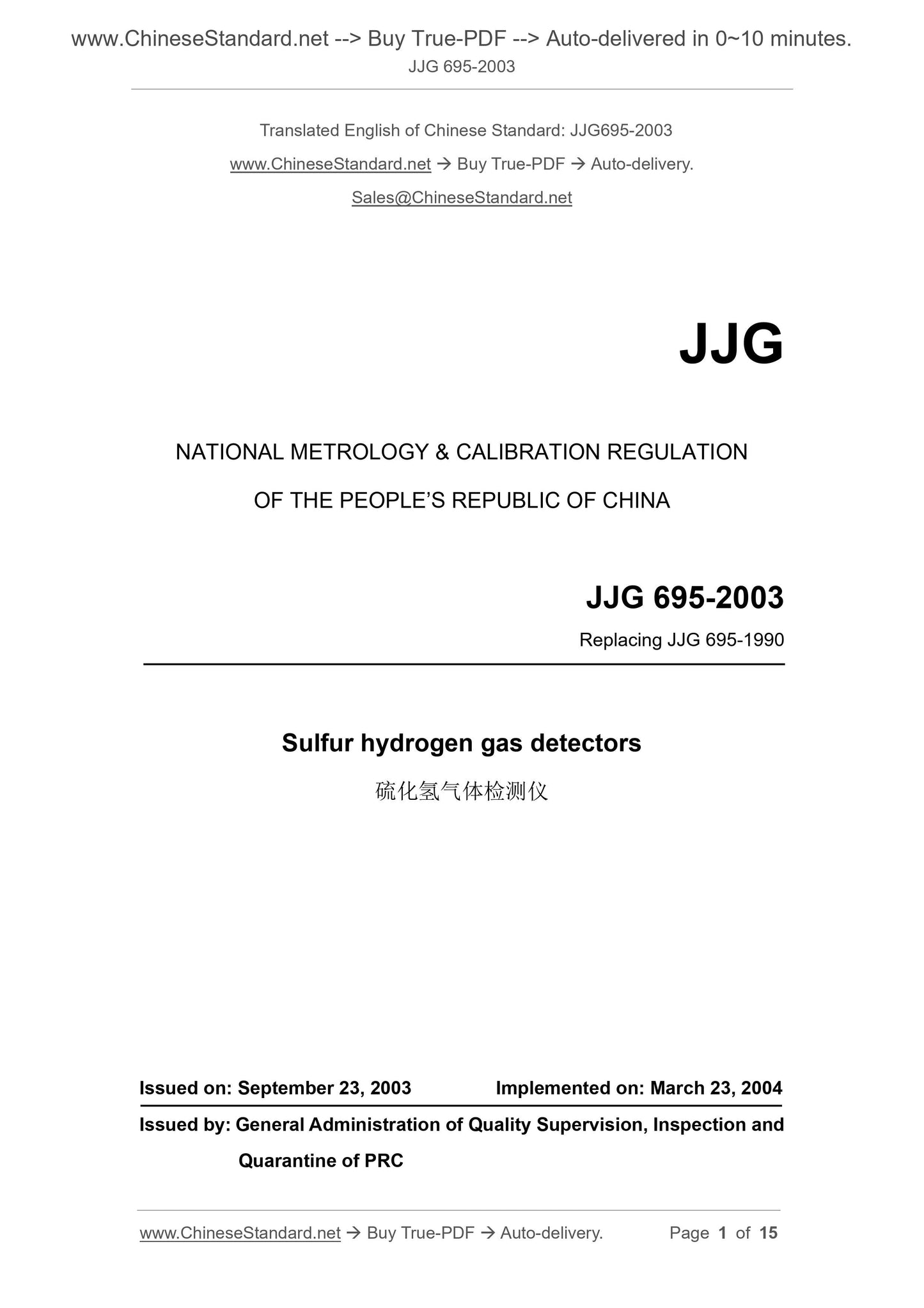
JJG 695-2003
NATIONAL METROLOGY and CALIBRATION REGULATION
OF THE PEOPLE’S REPUBLIC OF CHINA
Replacing JJG 695-1990
Sulfur hydrogen gas detectors
ISSUED ON: SEPTEMBER 23, 2003
IMPLEMENTED ON: MARCH 23, 2004
Issued by: General Administration of Quality Supervision, Inspection and
Quarantine of PRC
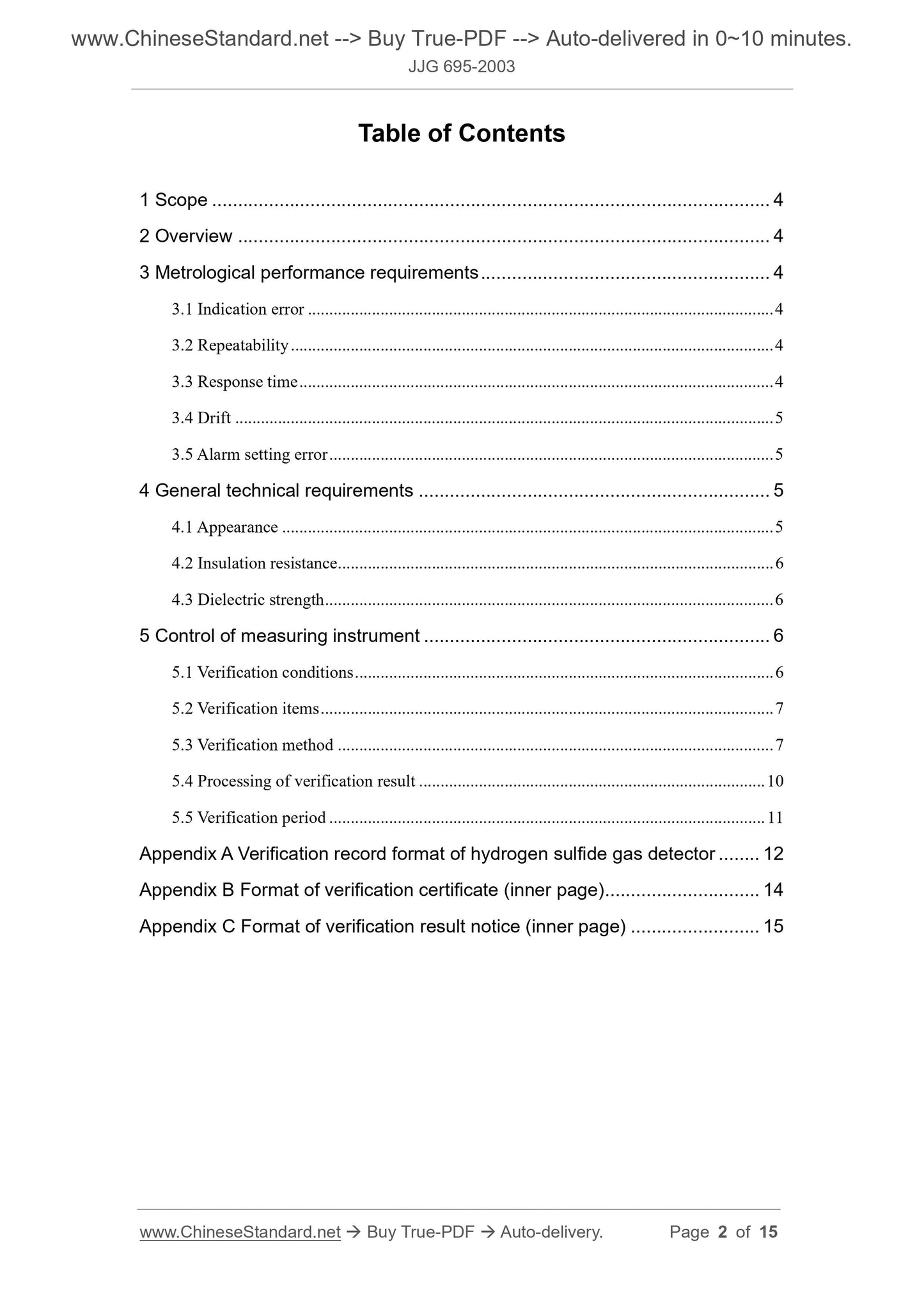
Table of Contents
1 Scope ... 4
2 Overview ... 4
3 Metrological performance requirements ... 4
3.1 Indication error ... 4
3.2 Repeatability ... 4
3.3 Response time ... 4
3.4 Drift ... 5
3.5 Alarm setting error ... 5
4 General technical requirements ... 5
4.1 Appearance ... 5
4.2 Insulation resistance ... 6
4.3 Dielectric strength ... 6
5 Control of measuring instrument ... 6
5.1 Verification conditions ... 6
5.2 Verification items ... 7
5.3 Verification method ... 7
5.4 Processing of verification result ... 10
5.5 Verification period ... 11
Appendix A Verification record format of hydrogen sulfide gas detector ... 12
Appendix B Format of verification certificate (inner page) ... 14
Appendix C Format of verification result notice (inner page) ... 15
Verification regulation of sulfur hydrogen gas
detectors
1 Scope
This regulation applies to the first verification, subsequent verification and in-
use inspection of hydrogen sulfide gas detectors.
2 Overview
The hydrogen sulfide gas detector (hereinafter referred to as the instrument)
mainly comprises an electrochemical sensor or an optical sensor, as well as an
electronic component and a display portion. The sensor converts hydrogen
sulfide gas in the environment into an electrical signal and displays it in a
concentration (molar fraction).
The instrument is divided into diffused type and pumped type.
3 Metrological performance requirements
3.1 Indication error
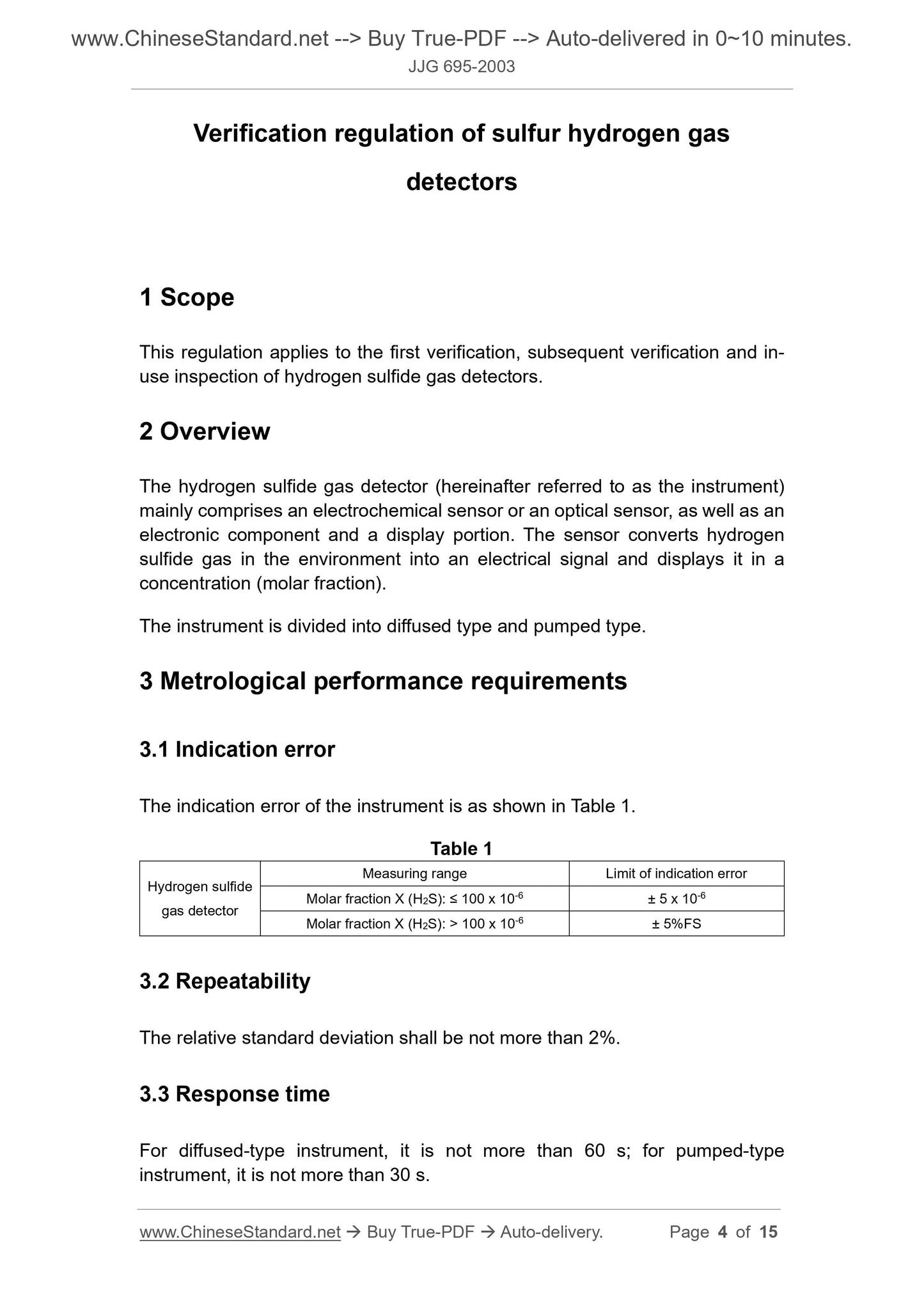
The indication error of the instrument is as shown in Table 1.
Table 1
Hydrogen sulfide
gas detector
Measuring range Limit of indication error
Molar fraction X (H2S): ≤ 100 x 10-6 ± 5 x 10⁻⁶
Molar fraction X (H2S): > 100 x 10-6 ± 5%FS
3.2 Repeatability
The relative standard deviation shall be not more than 2%.
3.3 Response time
For diffused-type instrument, it is not more than 60 s; for pumped-type
instrument, it is not more than 30 s.
observe whether the instrument has alarm sound and whether the alarm light
flashes, check the alarm set point of the instrument.
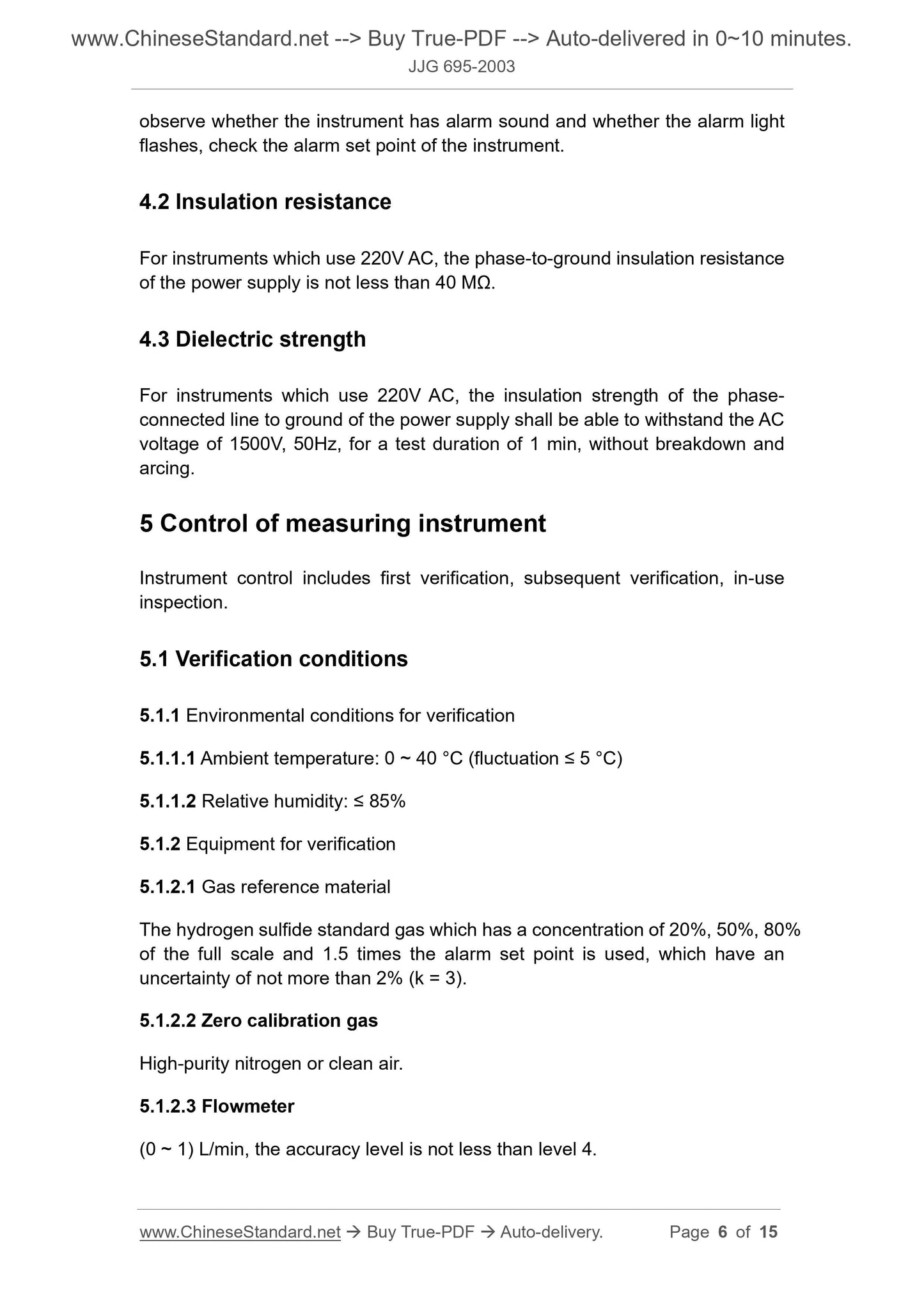
4.2 Insulation resistance
For instruments which use 220V AC, the phase-to-ground insulation resistance
of the power supply is not less than 40 MΩ.
4.3 Dielectric strength
For instruments which use 220V AC, the insulation strength of the phase-
connected line to ground of the power supply shall be able to withstand the AC
voltage of 1500V, 50Hz, for a test duration of 1 min, without breakdown and
arcing.
5 Control of measuring instrument
Instrument control includes first verification, subsequent verification, in-use
inspection.
5.1 Verification conditions
5.1.1 Environmental conditions for verification
5.1.1.1 Ambient temperature: 0 ~ 40 °C (fluctuation ≤ 5 °C)
5.1.1.2 Relative humidity: ≤ 85%
5.1.2 Equipment for verification
5.1.2.1 Gas reference material
The hydrogen sulfide standard gas which has a concentration of 20%, 50%, 80%
of the full scale and 1.5 times the alarm set point is used, which have an
uncertainty of not more than 2% (k = 3).
5.1.2.2 Zero calibration gas
High-purity nitrogen or clean air.
5.1.2.3 Flowmeter
(0 ~ 1) L/min, the accuracy level is not less than level 4.
for 1 min, the current is 5 mA. Then the voltage is smoothly lowered to 0 V. The
instrument shall not have breakdown and arcing during the whole test.
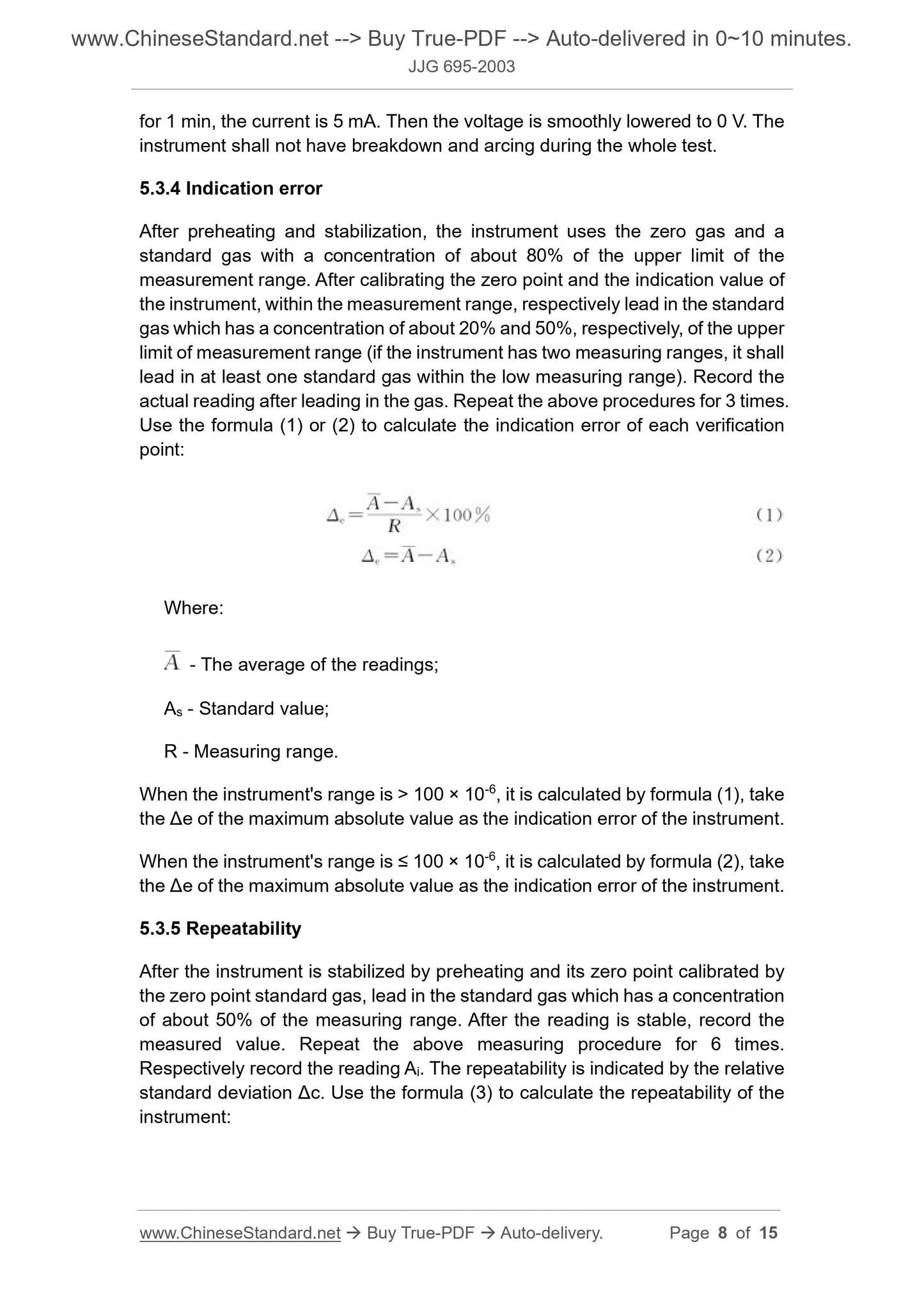
5.3.4 Indication error
After preheating and stabilization, the instrument uses the zero gas and a
standard gas with a concentration of about 80% of the upper limit of the
measurement range. After calibrating the zero point and the indication value of
the instrument, within the measurement range, respectively lead in the standard
gas which has a concentration of about 20% and 50%, respectively, of the upper
limit of measurement range (if the instrument has two measuring ranges, it shall
lead in at least one standard gas within the low measuring range). Record the
actual reading after leading in the gas. Repeat the above procedures for 3 times.
Use the formula (1) or (2) to calculate the indication error of each verification
point:
Where:
- The average of the readings;
As - Standard value;
R - Measuring range.
When the instrument's range is > 100 × 10-6, it is calculated by formula (1), take
the Δe of the maximum absolute value as the indication error of the instrument.
When the instrument's range is ≤ 100 × 10-6, it is calculated by formula (2), take
the Δe of the maximum absolute value as the indication error of the instrument.
5.3.5 Repeatability
After the instrument is stabilized by preheating and its zero point calibrated by
the zero point standard gas, lead in the standard gas which has a concentration
of about 50% of the measuring range. After the reading is stable, record the
measured value. Repeat the above measuring procedure for 6 times.
Respectively record the reading Ai. The repeatability is indicated by the relative
standard deviation Δc. Use the formula (3) to calculate the repeatability of the
instrument:
When the instrument's range is > 100 × 10-6, it is calculated by formula (4), take
the Δzi of the maximum absolute value as the zero drift of the instrument.
When the instrument's range is ≤ 100 × 10-6, it is calculated by formula (5), take
the Δzi of the maximum absolute value as the zero drift of the instrument.
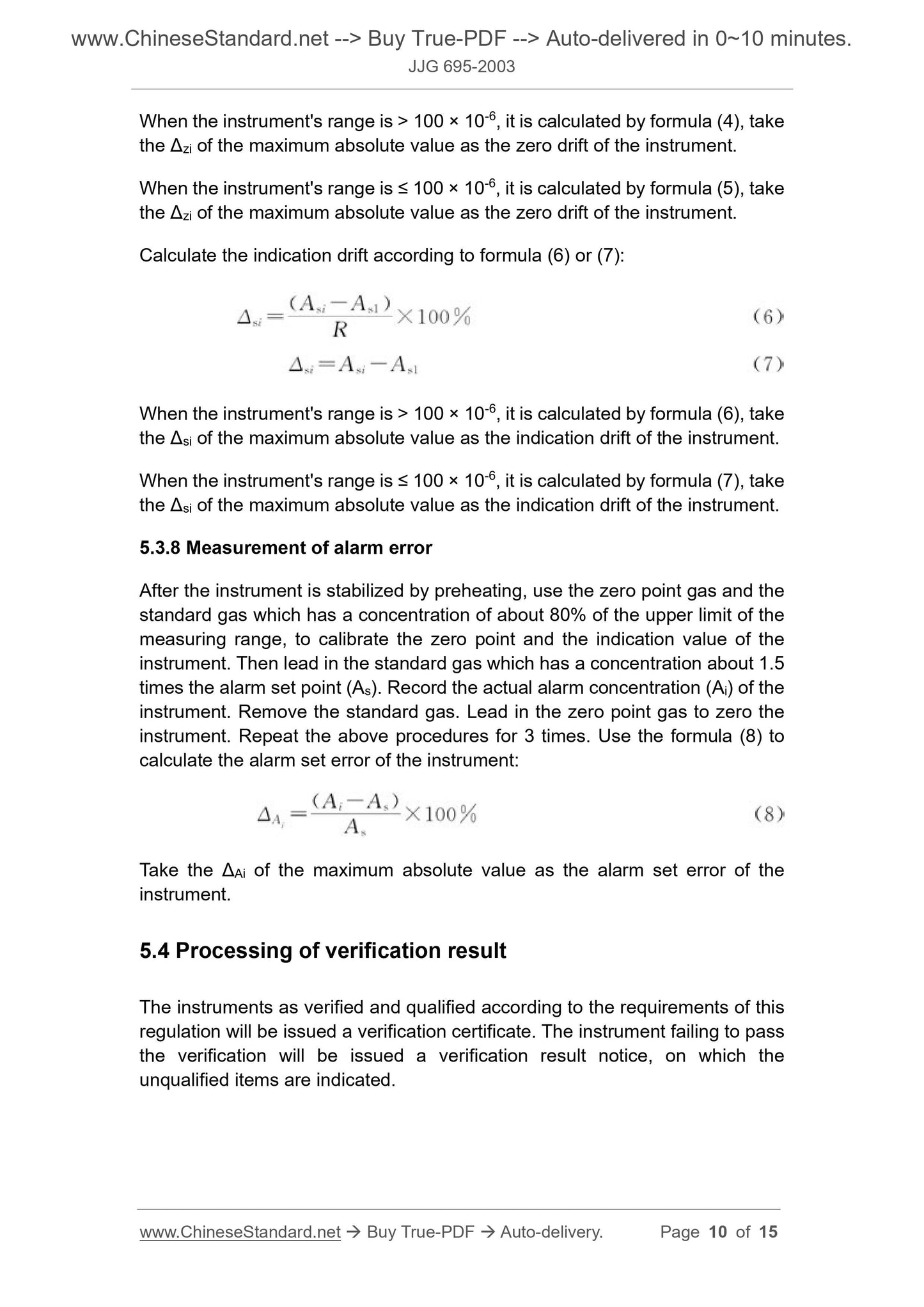
Calculate the indication drift according to formula (6) or (7):
When the instrument's range is > 100 × 10-6, it is calculated by formula (6), take
the Δsi of the maximum absolute value as the indication drift of the instrument.
When the instrument's range is ≤ 100 × 10-6, it is calculated by formula (7), take
the Δsi of the maximum absolute value as the indication drift of the instrument.
5.3.8 Measurement of alarm error
After the instrument is stabilized by preheating, use the zero point gas and the
standard gas which has a concentration of about 80% of the upper limit of the
measuring range, to calibrate the zero point and the indication value of the
instrument. Then lead in the standard gas which has a concentration about 1.5
times the alarm set point (As). Record the actual alarm concentration (Ai) of the
instrument. Remove the standard gas. Lead in the zero point gas to zero the
instrument. Repeat the above procedures for 3 times. Use the formula (8) to
calculate the alarm set error of the instrument:
Take the ΔAi of the maximum absolute value as the alarm set error of the
instrument.
5.4 Processing of verification result
The instruments as verified and qualified according to the requirements of this
regulation will be issued a verification certificate. The instrument failing to pass
the verification will be issued a verification result notice, on which the
unqualified items are indicated.
JJG 695-2003
NATIONAL METROLOGY and CALIBRATION REGULATION
OF THE PEOPLE’S REPUBLIC OF CHINA
Replacing JJG 695-1990
Sulfur hydrogen gas detectors
ISSUED ON: SEPTEMBER 23, 2003
IMPLEMENTED ON: MARCH 23, 2004
Issued by: General Administration of Quality Supervision, Inspection and
Quarantine of PRC
Table of Contents
1 Scope ... 4
2 Overview ... 4
3 Metrological performance requirements ... 4
3.1 Indication error ... 4
3.2 Repeatability ... 4
3.3 Response time ... 4
3.4 Drift ... 5
3.5 Alarm setting error ... 5
4 General technical requirements ... 5
4.1 Appearance ... 5
4.2 Insulation resistance ... 6
4.3 Dielectric strength ... 6
5 Control of measuring instrument ... 6
5.1 Verification conditions ... 6
5.2 Verification items ... 7
5.3 Verification method ... 7
5.4 Processing of verification result ... 10
5.5 Verification period ... 11
Appendix A Verification record format of hydrogen sulfide gas detector ... 12
Appendix B Format of verification certificate (inner page) ... 14
Appendix C Format of verification result notice (inner page) ... 15
Verification regulation of sulfur hydrogen gas
detectors
1 Scope
This regulation applies to the first verification, subsequent verification and in-
use inspection of hydrogen sulfide gas detectors.
2 Overview
The hydrogen sulfide gas detector (hereinafter referred to as the instrument)
mainly comprises an electrochemical sensor or an optical sensor, as well as an
electronic component and a display portion. The sensor converts hydrogen
sulfide gas in the environment into an electrical signal and displays it in a
concentration (molar fraction).
The instrument is divided into diffused type and pumped type.
3 Metrological performance requirements
3.1 Indication error
The indication error of the instrument is as shown in Table 1.
Table 1
Hydrogen sulfide
gas detector
Measuring range Limit of indication error
Molar fraction X (H2S): ≤ 100 x 10-6 ± 5 x 10⁻⁶
Molar fraction X (H2S): > 100 x 10-6 ± 5%FS
3.2 Repeatability
The relative standard deviation shall be not more than 2%.
3.3 Response time
For diffused-type instrument, it is not more than 60 s; for pumped-type
instrument, it is not more than 30 s.
observe whether the instrument has alarm sound and whether the alarm light
flashes, check the alarm set point of the instrument.
4.2 Insulation resistance
For instruments which use 220V AC, the phase-to-ground insulation resistance
of the power supply is not less than 40 MΩ.
4.3 Dielectric strength
For instruments which use 220V AC, the insulation strength of the phase-
connected line to ground of the power supply shall be able to withstand the AC
voltage of 1500V, 50Hz, for a test duration of 1 min, without breakdown and
arcing.
5 Control of measuring instrument
Instrument control includes first verification, subsequent verification, in-use
inspection.
5.1 Verification conditions
5.1.1 Environmental conditions for verification
5.1.1.1 Ambient temperature: 0 ~ 40 °C (fluctuation ≤ 5 °C)
5.1.1.2 Relative humidity: ≤ 85%
5.1.2 Equipment for verification
5.1.2.1 Gas reference material
The hydrogen sulfide standard gas which has a concentration of 20%, 50%, 80%
of the full scale and 1.5 times the alarm set point is used, which have an
uncertainty of not more than 2% (k = 3).
5.1.2.2 Zero calibration gas
High-purity nitrogen or clean air.
5.1.2.3 Flowmeter
(0 ~ 1) L/min, the accuracy level is not less than level 4.
for 1 min, the current is 5 mA. Then the voltage is smoothly lowered to 0 V. The
instrument shall not have breakdown and arcing during the whole test.
5.3.4 Indication error
After preheating and stabilization, the instrument uses the zero gas and a
standard gas with a concentration of about 80% of the upper limit of the
measurement range. After calibrating the zero point and the indication value of
the instrument, within the measurement range, respectively lead in the standard
gas which has a concentration of about 20% and 50%, respectively, of the upper
limit of measurement range (if the instrument has two measuring ranges, it shall
lead in at least one standard gas within the low measuring range). Record the
actual reading after leading in the gas. Repeat the above procedures for 3 times.
Use the formula (1) or (2) to calculate the indication error of each verification
point:
Where:
- The average of the readings;
As - Standard value;
R - Measuring range.
When the instrument's range is > 100 × 10-6, it is calculated by formula (1), take
the Δe of the maximum absolute value as the indication error of the instrument.
When the instrument's range is ≤ 100 × 10-6, it is calculated by formula (2), take
the Δe of the maximum absolute value as the indication error of the instrument.
5.3.5 Repeatability
After the instrument is stabilized by preheating and its zero point calibrated by
the zero point standard gas, lead in the standard gas which has a concentration
of about 50% of the measuring range. After the reading is stable, record the
measured value. Repeat the above measuring procedure for 6 times.
Respectively record the reading Ai. The repeatability is indicated by the relative
standard deviation Δc. Use the formula (3) to calculate the repeatability of the
instrument:
When the instrument's range is > 100 × 10-6, it is calculated by formula (4), take
the Δzi of the maximum absolute value as the zero drift of the instrument.
When the instrument's range is ≤ 100 × 10-6, it is calculated by formula (5), take
the Δzi of the maximum absolute value as the zero drift of the instrument.
Calculate the indication drift according to formula (6) or (7):
When the instrument's range is > 100 × 10-6, it is calculated by formula (6), take
the Δsi of the maximum absolute value as the indication drift of the instrument.
When the instrument's range is ≤ 100 × 10-6, it is calculated by formula (7), take
the Δsi of the maximum absolute value as the indication drift of the instrument.
5.3.8 Measurement of alarm error
After the instrument is stabilized by preheating, use the zero point gas and the
standard gas which has a concentration of about 80% of the upper limit of the
measuring range, to calibrate the zero point and the indication value of the
instrument. Then lead in the standard gas which has a concentration about 1.5
times the alarm set point (As). Record the actual alarm concentration (Ai) of the
instrument. Remove the standard gas. Lead in the zero point gas to zero the
instrument. Repeat the above procedures for 3 times. Use the formula (8) to
calculate the alarm set error of the instrument:
Take the ΔAi of the maximum absolute value as the alarm set error of the
instrument.
5.4 Processing of verification result
The instruments as veri...
Share
