1
/
of
12
www.ChineseStandard.us -- Field Test Asia Pte. Ltd.
QC/T 417.2-2001 English PDF (QC/T417.2-2001)
QC/T 417.2-2001 English PDF (QC/T417.2-2001)
Regular price
$125.00
Regular price
Sale price
$125.00
Unit price
/
per
Shipping calculated at checkout.
Couldn't load pickup availability
QC/T 417.2-2001: Connections for on-board electrical wiring harnesses - Part 2: Test methods and general performance requirements (motorcycle parts)
Delivery: 9 seconds. Download (& Email) true-PDF + Invoice.
Get Quotation: Click QC/T 417.2-2001 (Self-service in 1-minute)
Historical versions (Master-website): QC/T 417.2-2001
Preview True-PDF (Reload/Scroll-down if blank)
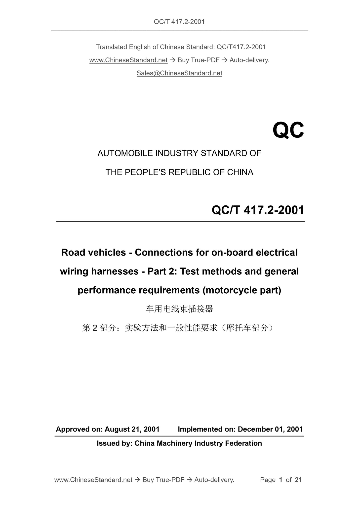
QC/T 417.2-2001
AUTOMOBILE INDUSTRY STANDARD OF
THE PEOPLE’S REPUBLIC OF CHINA
Road vehicles - Connections for on-board electrical
wiring harnesses - Part 2: Test methods and general
performance requirements (motorcycle part)
APPROVED ON: AUGUST 21, 2001
IMPLEMENTED ON: DECEMBER 01, 2001
Issued by: China Machinery Industry Federation
Table of Contents
1 Scope ... 3
2 Normative references ... 3
3 Definition ... 3
4 Test methods and performance requirements ... 4
5 Others ... 21
Road vehicles - Connections for on-board electrical
wiring harnesses - Part 2: Test methods and general
performance requirements (motorcycle part)
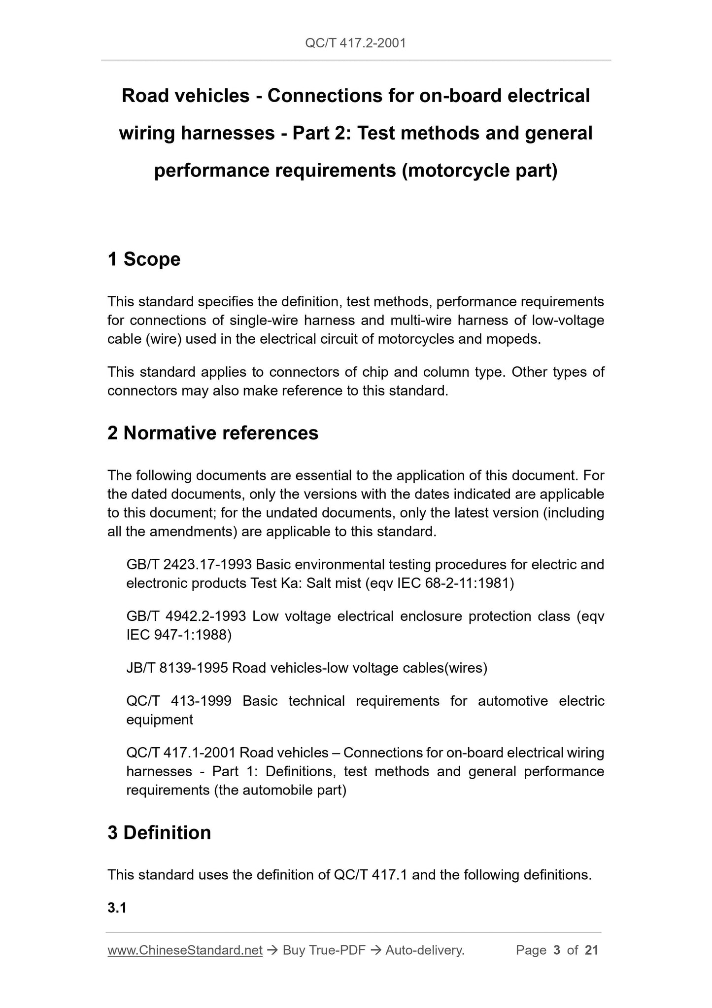
1 Scope
This standard specifies the definition, test methods, performance requirements
for connections of single-wire harness and multi-wire harness of low-voltage
cable (wire) used in the electrical circuit of motorcycles and mopeds.
This standard applies to connectors of chip and column type. Other types of
connectors may also make reference to this standard.
2 Normative references
The following documents are essential to the application of this document. For
the dated documents, only the versions with the dates indicated are applicable
to this document; for the undated documents, only the latest version (including
all the amendments) are applicable to this standard.
GB/T 2423.17-1993 Basic environmental testing procedures for electric and
electronic products Test Ka: Salt mist (eqv IEC 68-2-11:1981)
GB/T 4942.2-1993 Low voltage electrical enclosure protection class (eqv
IEC 947-1:1988)
JB/T 8139-1995 Road vehicles-low voltage cables(wires)
QC/T 413-1999 Basic technical requirements for automotive electric
equipment
QC/T 417.1-2001 Road vehicles – Connections for on-board electrical wiring
harnesses - Part 1: Definitions, test methods and general performance
requirements (the automobile part)
3 Definition
This standard uses the definition of QC/T 417.1 and the following definitions.
3.1
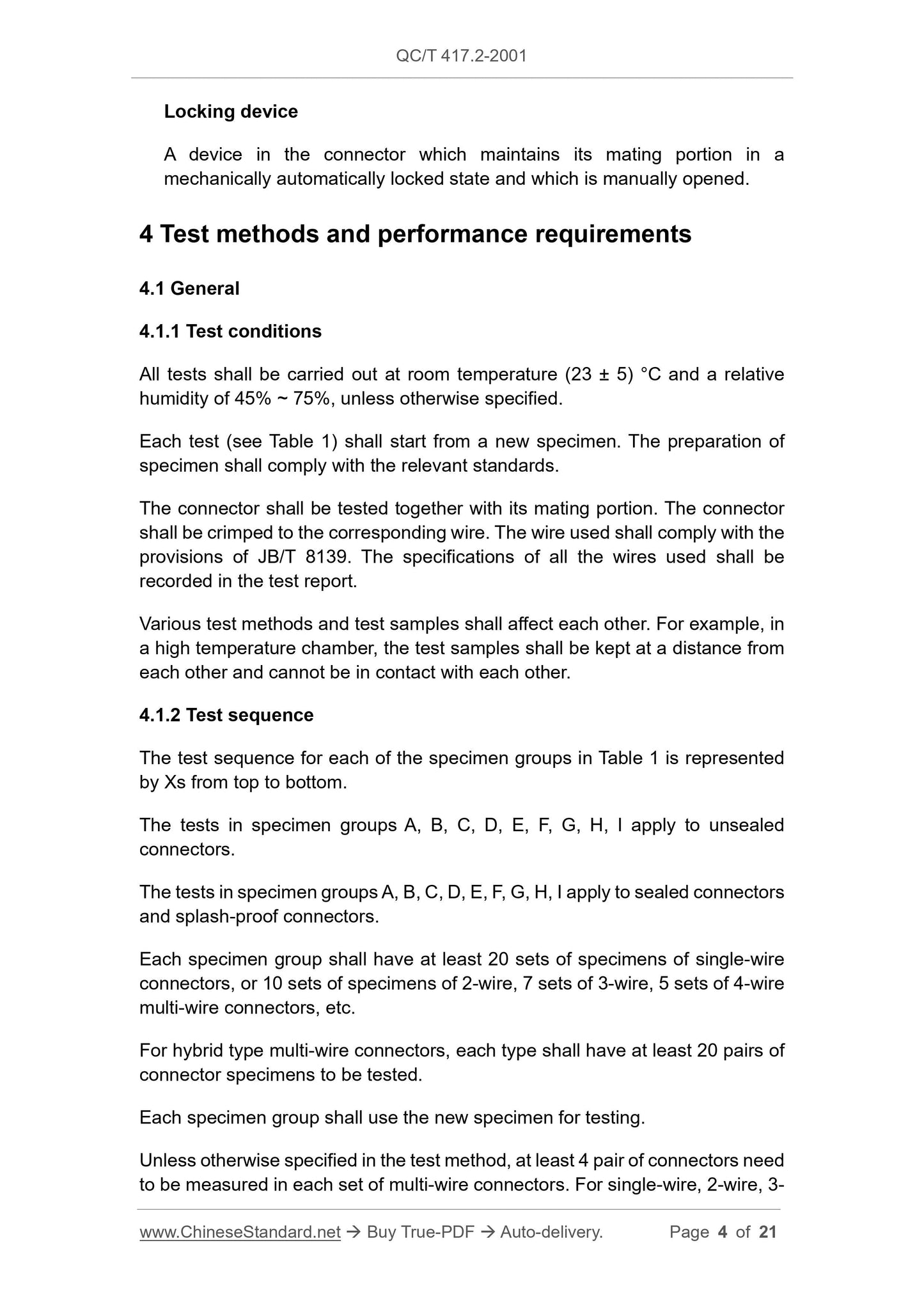
Locking device
A device in the connector which maintains its mating portion in a
mechanically automatically locked state and which is manually opened.
4 Test methods and performance requirements
4.1 General
4.1.1 Test conditions
All tests shall be carried out at room temperature (23 ± 5) °C and a relative
humidity of 45% ~ 75%, unless otherwise specified.
Each test (see Table 1) shall start from a new specimen. The preparation of
specimen shall comply with the relevant standards.
The connector shall be tested together with its mating portion. The connector
shall be crimped to the corresponding wire. The wire used shall comply with the
provisions of JB/T 8139. The specifications of all the wires used shall be
recorded in the test report.
Various test methods and test samples shall affect each other. For example, in
a high temperature chamber, the test samples shall be kept at a distance from
each other and cannot be in contact with each other.
4.1.2 Test sequence
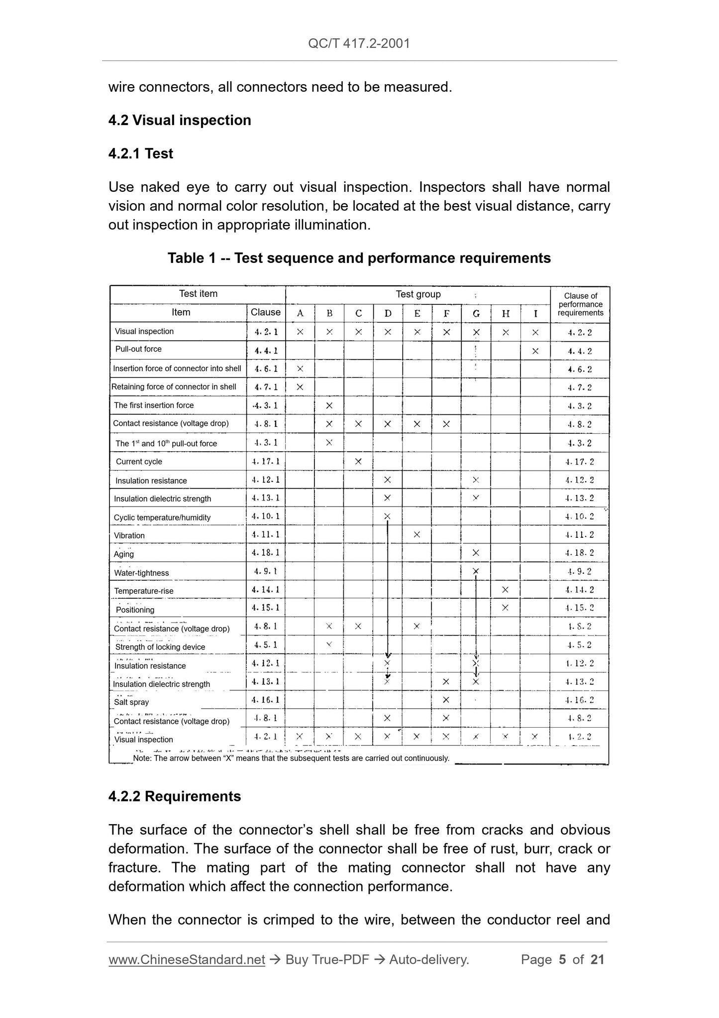
The test sequence for each of the specimen groups in Table 1 is represented
by Xs from top to bottom.
The tests in specimen groups A, B, C, D, E, F, G, H, I apply to unsealed
connectors.
The tests in specimen groups A, B, C, D, E, F, G, H, I apply to sealed connectors
and splash-proof connectors.
Each specimen group shall have at least 20 sets of specimens of single-wire
connectors, or 10 sets of specimens of 2-wire, 7 sets of 3-wire, 5 sets of 4-wire
multi-wire connectors, etc.
For hybrid type multi-wire connectors, each type shall have at least 20 pairs of
connector specimens to be tested.
Each specimen group shall use the new specimen for testing.
Unless otherwise specified in the test method, at least 4 pair of connectors need
to be measured in each set of multi-wire connectors. For single-wire, 2-wire, 3-
direction of the connector. Maintain stability for s.
4.5.1.2 Locking of connector
After the 11th insertion as specified in 4.3.1.2, apply a force of N in the
pullout direction of connector. Maintain stability for s.
4.5.2 Requirements
4.5.2.1 For the connector whose shell is locked, apply a static tension of
N in the pullout direction of the connector. Maintain it for s without falling
off or being damaged.
4.5.2.2 For the connector whose connection piece is locked, apply a static
tension of N in the pullout direction of the connector. Maintain it for
s without falling off or being damaged.
4.6 Insertion force of connector into shell
4.6.1 Test
When measuring the insertion force of the connector into the shell cavity, use
the test fixture to position the connection piece along the insertion direction.
The position shall be as close as possible to the insulation reel of wire.
Use a constant speed within the range of 50 mm/min ~ 150 mm/min to insert it
into the shell. The rate of application shall be recorded in the test report.
4.6.2 Requirements
After the connector is crimped to the wire as required, insert it into the shell
cavity. If the nominal cross-section of the conductor of the wire as crimped by
the connector is not more than 1 mm2, the insertion force is at most 15 N. If the
nominal cross-section of the conductor of the wire as crimped by the connector
is more than 1 mm2, the insertion force is at most 30 N.
4.7 Retaining force of connector in shell
4.7.1 Test
Use an appropriate test device to test the retaining force of the connector. In
front of or behind the connector, apply a constant force axially and maintain it
for s. The applied force shall be recorded in the test report.
4.7.2 Requirements
Insert each connector into the shell cavity. After inserting it in place, apply a
constant tension of 60 N along the axial direction of the crimped connection
between the connector and wire. Maintain it for s. The connector must
not be removed from the shell or damaged.
Depending on the insertion/pullout force, material, design requirements, it may
also require a higher retaining force.
For the sealed connector, the force as applied by the seal shall be included.
4.8 Contact resistance (voltage drop)
4.8.1 Test
4.8.1.1 Measurement at millivolt levels
The test voltage shall not exceed 20 mV of DC or AC peak voltage. The test
current shall not exceed 50 mA.
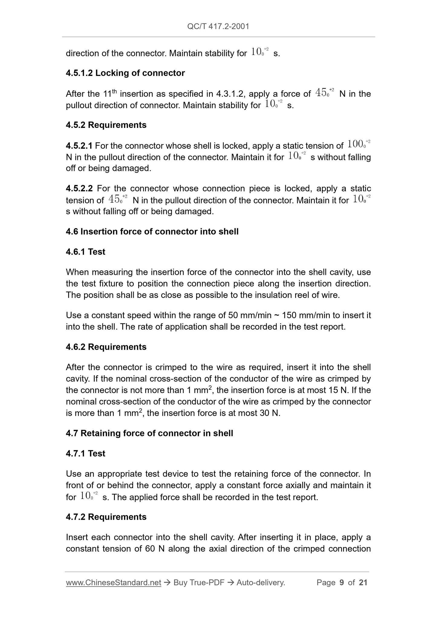
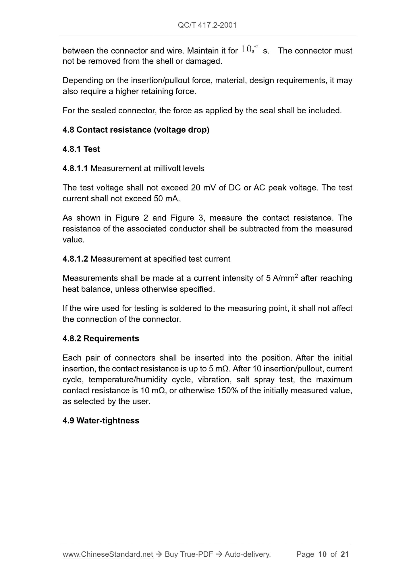
As shown in Figure 2 and Figure 3, measure the contact resistance. The
resistance of the associated conductor shall be subtracted from the measured
value.
4.8.1.2 Measurement at specified test current
Measurements shall be made at a current intensity of 5 A/mm2 after reaching
heat balance, unless otherwise specified.
If the wire used for testing is soldered to the measuring point, it shall not affect
the connection of the connector.
4.8.2 Requirements
Each pair of connectors shall be inserted into the position. After the initial
insertion, the contact resistance is up to 5 mΩ. After 10 insertion/pullout, current
cycle, temperature/humidity cycle, vibration, salt spray test, the maximum
contact resistance is 10 mΩ, or otherwise 150% of the initially measured value,
as selected by the user.
4.9 Water-tightness
If agreed by the manufacturer and the user, for the connectors of some special
purposes, the test voltage may be reduced to DC 100 V. The applied voltage
shall be recorded in the test report.
When a stable reading occurs, record the insulation resistance. However, after
the temperature/humidity cycle test, the unsealed and splash-proof connectors
shall be placed in the conditions as specified in 4.1.1 for 24 h, before measuring
the insulation resistance.
4.12.2 Requirements
According to the test sequence of Table 1, before and after the test, make
determination according to 4.12.1. The insulation resistance between the
connectors that are not connected in the connector as well as between the
connector and the shell shall be more than 100 MΩ.
4.13 Insulation dielectric strength
4.13.1 Test
Between the connectors which are not connected in the connector as well as
between the connector and the metal foil which wrap the shell, apply the AC
1000 V (50 Hz or 60 Hz) voltage or DC 1600 V voltage for 1 min. For the
purposes of safety, the metal foil shall be grounded.
4.13.2 Requirements
When tested according to 4.13.1, there shall be no breakdown or sparking.
4.14 Temperature-rise
4.14.1 Test
Use the mating connector of the simulated or actual wire-wire connection (see
Figure 2) or device connection (see Figure 3) to carry out the temperature-rise
test.
Crimp the specimen to a wire whose nominal cross-section of conductor is not
more than 2.5 mm2 and length is 200 mm ± 5 mm. For cables whose conductor
has a nominal cross-section of more than 2.5 mm2, the length shall be 500 mm
± 2 mm.
During the test, take care to protect the sample. Prevent ventilation and manual
cooling, for example, the cooling due to thermocouples.
The connector to be measured shall be able to reach the highest stable
temperature. A typical measurement surface is as shown in Figure 10.
Table 7 -- Conversion factors
4.16.2 Requirements
After the test according to 4.16.1, it shall follow the sequence of Table 1 to carry
out the subsequent tests.
4.17 Current cycle
4.17.1 Test
Use the specimen as specified in 4.14.1 to carry out the current cycle test.
According to the type of the mating connector used, based on the requirements
of Table 6, specify the specification of the crimped wire of the connector and
the test current.
Put the specimen into the test equipment. The temperature is as specified in
Table 8. Carry out 500 cycles of tests. Each cycle consists of 45 min of power-
on and 15 min of power-off.
Note: Avoid the specimen from ventilation and manual cooling.
Table 8 -- Categorized test temperature of current cycle
7.17.2 Requirements
After the test according to 4.17.1, it shall follow the sequence of Table 1 to carry
out the subsequent tests.
4.18 Aging
4.18.1 Test
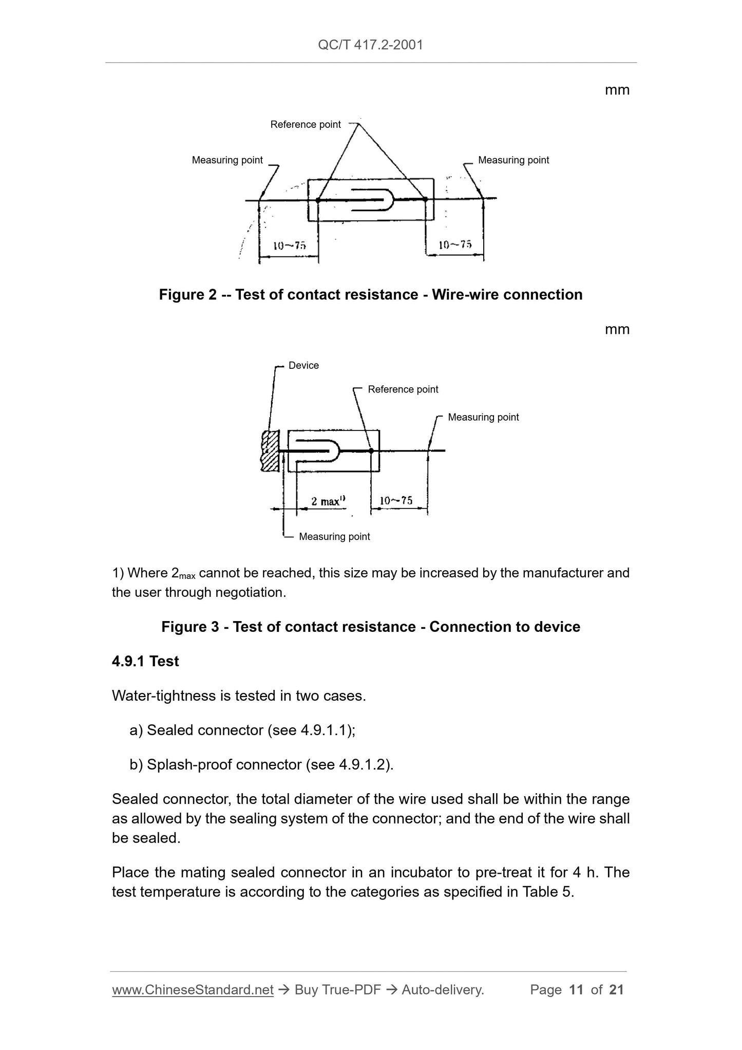
Put the connector in the test equipment for 100 h. The test temperature is as
specified in Table 5.
Note: If using another method, that is, the test temperature as specified in Table
8, the test time needs to be increased to 500 h.
4.18.2 Requirements
Number of lines of connector
Conversion factor
Category
Test temperature, °C (±2 °C)
QC/T 417.2-2001
AUTOMOBILE INDUSTRY STANDARD OF
THE PEOPLE’S REPUBLIC OF CHINA
Road vehicles - Connections for on-board electrical
wiring harnesses - Part 2: Test methods and general
performance requirements (motorcycle part)
APPROVED ON: AUGUST 21, 2001
IMPLEMENTED ON: DECEMBER 01, 2001
Issued by: China Machinery Industry Federation
Table of Contents
1 Scope ... 3
2 Normative references ... 3
3 Definition ... 3
4 Test methods and performance requirements ... 4
5 Others ... 21
Road vehicles - Connections for on-board electrical
wiring harnesses - Part 2: Test methods and general
performance requirements (motorcycle part)
1 Scope
This standard specifies the definition, test methods, performance requirements
for connections of single-wire harness and multi-wire harness of low-voltage
cable (wire) used in the electrical circuit of motorcycles and mopeds.
This standard applies to connectors of chip and column type. Other types of
connectors may also make reference to this standard.
2 Normative references
The following documents are essential to the application of this document. For
the dated documents, only the versions with the dates indicated are applicable
to this document; for the undated documents, only the latest version (including
all the amendments) are applicable to this standard.
GB/T 2423.17-1993 Basic environmental testing procedures for electric and
electronic products Test Ka: Salt mist (eqv IEC 68-2-11:1981)
GB/T 4942.2-1993 Low voltage electrical enclosure protection class (eqv
IEC 947-1:1988)
JB/T 8139-1995 Road vehicles-low voltage cables(wires)
QC/T 413-1999 Basic technical requirements for automotive electric
equipment
QC/T 417.1-2001 Road vehicles – Connections for on-board electrical wiring
harnesses - Part 1: Definitions, test methods and general performance
requirements (the automobile part)
3 Definition
This standard uses the definition of QC/T 417.1 and the following definitions.
3.1
Locking device
A device in the connector which maintains its mating portion in a
mechanically automatically locked state and which is manually opened.
4 Test methods and performance requirements
4.1 General
4.1.1 Test conditions
All tests shall be carried out at room temperature (23 ± 5) °C and a relative
humidity of 45% ~ 75%, unless otherwise specified.
Each test (see Table 1) shall start from a new specimen. The preparation of
specimen shall comply with the relevant standards.
The connector shall be tested together with its mating portion. The connector
shall be crimped to the corresponding wire. The wire used shall comply with the
provisions of JB/T 8139. The specifications of all the wires used shall be
recorded in the test report.
Various test methods and test samples shall affect each other. For example, in
a high temperature chamber, the test samples shall be kept at a distance from
each other and cannot be in contact with each other.
4.1.2 Test sequence
The test sequence for each of the specimen groups in Table 1 is represented
by Xs from top to bottom.
The tests in specimen groups A, B, C, D, E, F, G, H, I apply to unsealed
connectors.
The tests in specimen groups A, B, C, D, E, F, G, H, I apply to sealed connectors
and splash-proof connectors.
Each specimen group shall have at least 20 sets of specimens of single-wire
connectors, or 10 sets of specimens of 2-wire, 7 sets of 3-wire, 5 sets of 4-wire
multi-wire connectors, etc.
For hybrid type multi-wire connectors, each type shall have at least 20 pairs of
connector specimens to be tested.
Each specimen group shall use the new specimen for testing.
Unless ot...
Share
