1
/
von
6
PayPal, credit cards. Download editable-PDF and invoice in 1 second!
GA/T 537-2005 English PDF (GAT537-2005)
GA/T 537-2005 English PDF (GAT537-2005)
Normaler Preis
$160.00 USD
Normaler Preis
Verkaufspreis
$160.00 USD
Grundpreis
/
pro
Versand wird beim Checkout berechnet
Verfügbarkeit für Abholungen konnte nicht geladen werden
Delivery: 3 seconds. Download true-PDF + Invoice.
Get QUOTATION in 1-minute: Click GA/T 537-2005
Historical versions: GA/T 537-2005
Preview True-PDF (Reload/Scroll if blank)
GA/T 537-2005: Flame-retardant, fire-proof, fire resistance specifications of testing method of bus bar trunking system (busways)
GA/T 537-2005
GA
PUBLIC SECURITY INDUSTRY STANDARD
OF THE PEOPLE’S REPUBLIC OF CHINA
ICS 13.220.50
C 82
Flame-retardant, fire-proof, fire resistance specifications
of testing method of busbar trunking system (busways)
ISSUED ON. MARCH 17, 2005
IMPLEMENTED ON. OCTOBER 01, 2005
Issued by. Ministry of Public Security of People’s Republic of China
Table of Contents
1 Scope .. 4
2 Normative references .. 4
3 Terms and definitions .. 4
4 Test methods .. 6
5 Test report .. 14
Appendix A (Normative) Spray test method .. 15
References . 19
Flame-retardant, fire-proof, fire resistance specifications
of testing method of busbar trunking system (busways)
1 Scope
This standard specifies the test device, test conditions, test piece requirements,
test procedures, determination conditions, and test reports for the flame-
retardant, fire-proof, and fire-resistant properties of the busbar trunking system
(busways).
This standard applies to busbar trunking system (busways) which has a
nominal AC voltage of not more than 1000 V and a frequency of 50 Hz or 60
Hz.
2 Normative references
The provisions in following documents become the provisions of this Standard
through reference in this Standard. For the dated references, the subsequent
amendments (excluding corrections) or revisions do not apply to this Standard;
however, parties who reach an agreement based on this Standard are
encouraged to study if the latest versions of these documents are applicable.
For undated references, the latest edition of the referenced document applies.
GB/T 9978-1999 Fire-resistance tests - Elements of building construction
(neq ISO/FDIS 834-1.1997 E)
GB 13539.5-1999 Low-voltage fuses Part 3. Supplementary requirements
for fuses for use by unskilled persons (fuses for mainly for household and
similar application) examples of standardized fuses (idt IEC 60296-3-1.1999)
GB/T 18380.3-2001 Tests on electric cables under fire conditions - Part 3.
Tests on bunched wires or cables (idt IEC 60332-3.1992)
GB/T 19216.11-2003 Tests for electric cables under fire conditions - Circuit
integrity - Part 11. Apparatus - Fire alone at a flame temperature of at least
750 °C (idt IEC 60331-11.1992)
3 Terms and definitions
The following terms and definitions apply to this standard.
2.7 in GB/T 18380.3-2001, the time for the fire is 40 min.
4.1.5 Judgment conditions
If the test pieces do not burn or the maximum height of the inner and the three
outer surfaces of the carbonized part does not exceed 2.5 m, the flame
retardant performance is considered to be acceptable.
4.2 Fire-proof performance test method
4.2.1 Test device
It shall comply with the provisions of chapter 4 of GB/T 9978-1999.
4.2.2 Test conditions
4.2.2.1 Temperature rise conditions
It shall comply with the provisions of 5.1 of GB/T 9978-1999.
4.2.2.2 Pressure conditions
It shall comply with the provisions of 5.2 of GB/T 9978-1999.
4.2.2.3 Fire conditions
The test piece is surrounded by fire, unless otherwise there is actual
engineering requirement.
4.2.3 Test piece requirements
The fireproof straight length busbar trunking unit has a length of 1800 mm.
4.2.4 Installation
The support structure of the test piece during the test may use a precast
concrete floor or a brick wall. In accordance with the actual installation in the
building, the test piece is installed in the reserved hole on the support structure.
The test piece shall be in the positive pressure zone of the test device, the
distance to the two sides and the upper side of the test device shall not be less
than 200 mm; when multiple test pieces are tested at the same time, the
distance between each test piece shall not be less than 200 mm. The fire-proof
performance of the support structure shall meet the fire-proof performance
requirements of the test piece.
The gap between the reserved hole on the support structure and the test piece
is sealed with a non-flammable heat insulation material, the firing end of the test
piece is sealed and wrapped with a non-flammable heat insulation material, the
packing length and the test piece support structure are same in thickness.
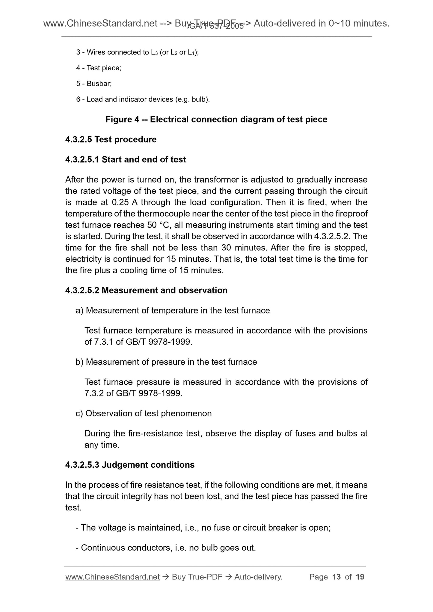
3 - Wires connected to L3 (or L2 or L1);
4 - Test piece;
5 - Busbar;
6 - Load and indicator devices (e.g. bulb).
Figure 4 -- Electrical connection diagram of test piece
4.3.2.5 Test procedure
4.3.2.5.1 Start and end of test
After the power is turned on, the transformer is adjusted to gradually increase
the rated voltage of the test piece, and the current passing through the circuit
is made at 0.25 A through the load configuration. Then it is fired, when the
temperature of the thermocouple near the center of the test piece in the fireproof
test furnace reaches 50 °C, all measuring instruments start timing and the test
is started. During the test, it shall be observed in accordance with 4.3.2.5.2. The
time for the fire shall not be less than 30 minutes. After the fire is stopped,
electricity is continued for 15 minutes. That is, the total test time is the time for
the fire plus a cooling time of 15 minutes.
4.3.2.5.2 Measurement and observation
a) Measurement of temperature in the test furnace
Test furnace temperature is measured in accordance with the provisions
of 7.3.1 of GB/T 9978-1999.
b) Measurement of pressure in the test furnace
Test furnace pressure is measured in accordance with the provisions of
7.3.2 of GB/T 9978-1999.
c) Observation of test phenomenon
During the fire-resistance test, observe the display of fuses and bulbs at
any time.
4.3.2.5.3 Judgement conditions
In the process of fire resistance test, if the following conditions are met, it means
that the circuit integrity has not been lost, and the test piece has passed the fire
test.
- The voltage is maintained, i.e., no fuse or circuit breaker is open;
- Continuous conductors, i.e. no bulb goes out.
Appendix A
(Normative)
Spray test method
The test shall be conducted in a suitable cabinet or test chamber. The cabinet
(or test chamber) shall have facilities for the treatment of any harmful gases
produced by the combustion and shall be sufficiently ventilated to maintain the
flame during the test.
Note. Examples of suitable cabinets are as specified in GB/T 17651.1.
The ambient temperature of the cabinet (or) outside the test chamber shall be
guaranteed between 5°C and 40°C.
Note 1. Barriers, such as the baffles specified in GB/T 17651.1, may be placed in a suitable
place to protect the torch so that ventilation does not affect the geometry of the flame.
Note 2. The tests specified in this part may involve voltages and temperatures that are harmful
to humans. Appropriate measures should be taken to prevent possible impact, combustion, fire,
explosion and other hazards, and to prevent any harmful gases that may be generated.
A.1 Test device
A.1.1 Heating device
The heating device specified in this standard conforms to the provisions of GB/T
19216.11-2003/IEC 60331-11.1999. If a heating device cannot meet the
requirements of the four-side firing requirements of the test piece, two sets of
heating devices can be used on both sides of the test piece for simultaneous
heating.
A.1.2 Spraying device
As shown in Figure A, the standard nozzle inner diameter. 6.3 mm, water spray
rate. (12.5 ± 0.625) L/min, nozzle pressure. about 30 kPa (equivalent to a
vertical upward free jet height of ...
Get QUOTATION in 1-minute: Click GA/T 537-2005
Historical versions: GA/T 537-2005
Preview True-PDF (Reload/Scroll if blank)
GA/T 537-2005: Flame-retardant, fire-proof, fire resistance specifications of testing method of bus bar trunking system (busways)
GA/T 537-2005
GA
PUBLIC SECURITY INDUSTRY STANDARD
OF THE PEOPLE’S REPUBLIC OF CHINA
ICS 13.220.50
C 82
Flame-retardant, fire-proof, fire resistance specifications
of testing method of busbar trunking system (busways)
ISSUED ON. MARCH 17, 2005
IMPLEMENTED ON. OCTOBER 01, 2005
Issued by. Ministry of Public Security of People’s Republic of China
Table of Contents
1 Scope .. 4
2 Normative references .. 4
3 Terms and definitions .. 4
4 Test methods .. 6
5 Test report .. 14
Appendix A (Normative) Spray test method .. 15
References . 19
Flame-retardant, fire-proof, fire resistance specifications
of testing method of busbar trunking system (busways)
1 Scope
This standard specifies the test device, test conditions, test piece requirements,
test procedures, determination conditions, and test reports for the flame-
retardant, fire-proof, and fire-resistant properties of the busbar trunking system
(busways).
This standard applies to busbar trunking system (busways) which has a
nominal AC voltage of not more than 1000 V and a frequency of 50 Hz or 60
Hz.
2 Normative references
The provisions in following documents become the provisions of this Standard
through reference in this Standard. For the dated references, the subsequent
amendments (excluding corrections) or revisions do not apply to this Standard;
however, parties who reach an agreement based on this Standard are
encouraged to study if the latest versions of these documents are applicable.
For undated references, the latest edition of the referenced document applies.
GB/T 9978-1999 Fire-resistance tests - Elements of building construction
(neq ISO/FDIS 834-1.1997 E)
GB 13539.5-1999 Low-voltage fuses Part 3. Supplementary requirements
for fuses for use by unskilled persons (fuses for mainly for household and
similar application) examples of standardized fuses (idt IEC 60296-3-1.1999)
GB/T 18380.3-2001 Tests on electric cables under fire conditions - Part 3.
Tests on bunched wires or cables (idt IEC 60332-3.1992)
GB/T 19216.11-2003 Tests for electric cables under fire conditions - Circuit
integrity - Part 11. Apparatus - Fire alone at a flame temperature of at least
750 °C (idt IEC 60331-11.1992)
3 Terms and definitions
The following terms and definitions apply to this standard.
2.7 in GB/T 18380.3-2001, the time for the fire is 40 min.
4.1.5 Judgment conditions
If the test pieces do not burn or the maximum height of the inner and the three
outer surfaces of the carbonized part does not exceed 2.5 m, the flame
retardant performance is considered to be acceptable.
4.2 Fire-proof performance test method
4.2.1 Test device
It shall comply with the provisions of chapter 4 of GB/T 9978-1999.
4.2.2 Test conditions
4.2.2.1 Temperature rise conditions
It shall comply with the provisions of 5.1 of GB/T 9978-1999.
4.2.2.2 Pressure conditions
It shall comply with the provisions of 5.2 of GB/T 9978-1999.
4.2.2.3 Fire conditions
The test piece is surrounded by fire, unless otherwise there is actual
engineering requirement.
4.2.3 Test piece requirements
The fireproof straight length busbar trunking unit has a length of 1800 mm.
4.2.4 Installation
The support structure of the test piece during the test may use a precast
concrete floor or a brick wall. In accordance with the actual installation in the
building, the test piece is installed in the reserved hole on the support structure.
The test piece shall be in the positive pressure zone of the test device, the
distance to the two sides and the upper side of the test device shall not be less
than 200 mm; when multiple test pieces are tested at the same time, the
distance between each test piece shall not be less than 200 mm. The fire-proof
performance of the support structure shall meet the fire-proof performance
requirements of the test piece.
The gap between the reserved hole on the support structure and the test piece
is sealed with a non-flammable heat insulation material, the firing end of the test
piece is sealed and wrapped with a non-flammable heat insulation material, the
packing length and the test piece support structure are same in thickness.
3 - Wires connected to L3 (or L2 or L1);
4 - Test piece;
5 - Busbar;
6 - Load and indicator devices (e.g. bulb).
Figure 4 -- Electrical connection diagram of test piece
4.3.2.5 Test procedure
4.3.2.5.1 Start and end of test
After the power is turned on, the transformer is adjusted to gradually increase
the rated voltage of the test piece, and the current passing through the circuit
is made at 0.25 A through the load configuration. Then it is fired, when the
temperature of the thermocouple near the center of the test piece in the fireproof
test furnace reaches 50 °C, all measuring instruments start timing and the test
is started. During the test, it shall be observed in accordance with 4.3.2.5.2. The
time for the fire shall not be less than 30 minutes. After the fire is stopped,
electricity is continued for 15 minutes. That is, the total test time is the time for
the fire plus a cooling time of 15 minutes.
4.3.2.5.2 Measurement and observation
a) Measurement of temperature in the test furnace
Test furnace temperature is measured in accordance with the provisions
of 7.3.1 of GB/T 9978-1999.
b) Measurement of pressure in the test furnace
Test furnace pressure is measured in accordance with the provisions of
7.3.2 of GB/T 9978-1999.
c) Observation of test phenomenon
During the fire-resistance test, observe the display of fuses and bulbs at
any time.
4.3.2.5.3 Judgement conditions
In the process of fire resistance test, if the following conditions are met, it means
that the circuit integrity has not been lost, and the test piece has passed the fire
test.
- The voltage is maintained, i.e., no fuse or circuit breaker is open;
- Continuous conductors, i.e. no bulb goes out.
Appendix A
(Normative)
Spray test method
The test shall be conducted in a suitable cabinet or test chamber. The cabinet
(or test chamber) shall have facilities for the treatment of any harmful gases
produced by the combustion and shall be sufficiently ventilated to maintain the
flame during the test.
Note. Examples of suitable cabinets are as specified in GB/T 17651.1.
The ambient temperature of the cabinet (or) outside the test chamber shall be
guaranteed between 5°C and 40°C.
Note 1. Barriers, such as the baffles specified in GB/T 17651.1, may be placed in a suitable
place to protect the torch so that ventilation does not affect the geometry of the flame.
Note 2. The tests specified in this part may involve voltages and temperatures that are harmful
to humans. Appropriate measures should be taken to prevent possible impact, combustion, fire,
explosion and other hazards, and to prevent any harmful gases that may be generated.
A.1 Test device
A.1.1 Heating device
The heating device specified in this standard conforms to the provisions of GB/T
19216.11-2003/IEC 60331-11.1999. If a heating device cannot meet the
requirements of the four-side firing requirements of the test piece, two sets of
heating devices can be used on both sides of the test piece for simultaneous
heating.
A.1.2 Spraying device
As shown in Figure A, the standard nozzle inner diameter. 6.3 mm, water spray
rate. (12.5 ± 0.625) L/min, nozzle pressure. about 30 kPa (equivalent to a
vertical upward free jet height of ...
Share