1
/
von
7
PayPal, credit cards. Download editable-PDF and invoice in 1 second!
GB/T 30832-2014 English PDF (GBT30832-2014)
GB/T 30832-2014 English PDF (GBT30832-2014)
Normaler Preis
$230.00 USD
Normaler Preis
Verkaufspreis
$230.00 USD
Grundpreis
/
pro
Versand wird beim Checkout berechnet
Verfügbarkeit für Abholungen konnte nicht geladen werden
Delivery: 3 seconds. Download true-PDF + Invoice.
Get QUOTATION in 1-minute: Click GB/T 30832-2014
Historical versions: GB/T 30832-2014
Preview True-PDF (Reload/Scroll if blank)
GB/T 30832-2014: Valves -- Test method of flow coefficient and flow resistance coefficient
GB/T 30832-2014
GB
NATIONAL STANDARD OF THE
PEOPLE’S REPUBLIC OF CHINA
ICS 23.060.01
J 16
Valves - Test method of flow coefficient
and flow resistance coefficient
ISSUED ON. JUNE 24, 2014
IMPLEMENTED ON. MARCH 01, 2015
Issued by. General Administration of Quality Supervision, Inspection and
Quarantine;
Standardization Administration Committee.
Table of Contents
Foreword ... 3
1 Scope ... 4
2 Normative references ... 4
3 Terms and definitions ... 4
4 Test equipment and measuring instruments ... 5
5 Test requirements ... 9
6 Test procedures ... 10
7 Calculation ... 11
8 Test report ... 13
Annex A (informative) Flow characteristics of fluid in valve ... 14
Annex B (informative) Error analysis of test results ... 18
Valves - Test method of flow coefficient
and flow resistance coefficient
1 Scope
This Standard specifies the terms and definitions, test equipment and
measuring instruments, test requirements, test procedures, calculation and test
report for the test of flow coefficient and flow resistance coefficient.
This Standard applies to.
a) the test of flow-pressure loss, flow coefficient and flow resistance
coefficient of valves, pipeline filters, etc. with water as medium;
b) the flow resistance coefficient value of the tested product is greater
than 0.1.
The test of flow-pressure loss, flow coefficient and flow resistance coefficient of
other similar valves and pipeline shall refer to the methods in this Standard.
2 Normative references
The following referenced documents are indispensable for the application of
this document. For dated references, only the edition cited applies. For undated
references, the latest edition of the referenced document (including any
amendments) applies.
GB/T 3101, Quantities and units - General principles
GB/T 17395, Dimensions, shapes, masses and tolerances of seamless steel
pipes
3 Terms and definitions
For the purposes of this document, the following terms and definitions apply.
3.1 flow; Q
the volume of water flowing through the valve per unit time, in m3/h
3.2 pressure drop; Δp
the circulation of the pipeline.
4.2 Connection pipeline
4.2.1 All the pipeline s before and after the flow meter connection pipeline and
test valve shall be round straight pipe. There must be no protrusions, pits, etc.
The dimension and deviation of the pipeline shall comply with the provisions of
GB/T 17395. The inner surface of the pipeline shall be clean, free from oxide
scales and other obstacles that may cause fluid disturbances. The connection
end of the pipeline on which the flow measuring instrument and the test valve
are to be installed shall be straight.
4.2.2 As shown in Figure 1 or Figure 2, L1 ~ L5 refer to the length of the straight
pipe section of the same nominal size as the test valve. L1 is the measuring
pipe section used to measure the flow-pressure drop of the test valve
connection pipeline itself. L2 and L3 are the pressure tapping point pipe sections
of upstream and downstream connection pipelines of the test valve. L4 is the
straight pipe section after the downstream pressure tapping point of the test
valve. L5 is the length of the straight pipe before the pipeline pressure tapping
point.
4.2.3 The lengths of the connection pipeline of the test value and the pressure
tapping point are required as. L2 shall be greater than or equal to 5 times the
nominal size of the pipeline; L3 shall be greater than or equal to 10 times the
nominal size of the pipeline; L4 shall be greater than 5 times the nominal size
of the connection pipeline. Where the L1 straight pipe section is set in the test
system, L1 shall be the sum of the lengths of L2 and L3, the length of L5 shall be
15 times larger than the nominal size of the pipeline. If the test system does not
set the L1 straight pipe section, the length of L5 shall be 18 times larger than the
nominal size of the pipeline. If the rectifying vane is used in the L5 pipe section,
the length can be shortened to 8 times the nominal pipeline size.
4.2.4 The length of the connection pipeline of the flow measuring instrument
shall meet the requirements of the flow measuring instrument for the length of
the connection pipeline. The inner diameters of the connection pipeline and the
flange shall not be less than the inner diameter of the flowmeter. It is better to
approach the inner diameter of the flowmeter.
4.2.5 Except for the valve connected to the threaded end, the inner diameter of
the pipeline connected to the test valve shall not be less than the inner diameter
of the connection end of the test valve.
4.2.6 The end face of the connection pipe of the threaded end valve shall try to
reach the step at the bottom of the valve thread.
4.3 Pressure tap and connection pipe
Standard, the error of the test result can be analyzed according to Annex B.
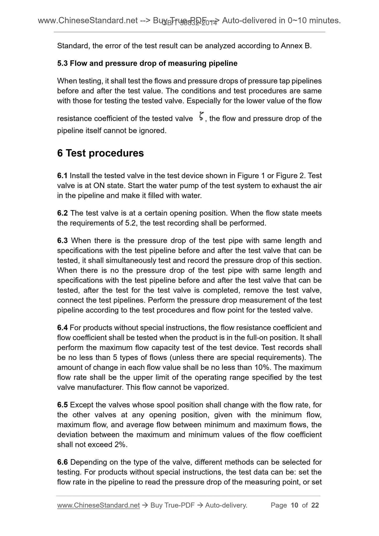
5.3 Flow and pressure drop of measuring pipeline
When testing, it shall test the flows and pressure drops of pressure tap pipelines
before and after the test value. The conditions and test procedures are same
with those for testing the tested valve. Especially for the lower value of the flow
resistance coefficient of the tested valve , the flow and pressure drop of the
pipeline itself cannot be ignored.
6 Test procedures
6.1 Install the tested valve in the test device shown in Figure 1 or Figure 2. Test
valve is at ON state. Start the water pump of the test system to exhaust the air
in the pipeline and make it filled with water.
6.2 The test valve is at a certain opening position. When the flow state meets
the requirements of 5.2, the test recording shall be performed.
6.3 When there is the pressure drop of the test pipe with same length and
specifications with the test pipeline before and after the test valve that can be
tested, it shall simultaneously test and record the pressure drop of this section.
When there is no the pressure drop of the test pipe with same length and
specifications with the test pipeline before and after the test valve that can be
tested, after the test for the test valve is completed, remove the test valve,
connect the test pipelines. Perform the pressure drop measurement of the test
pipeline according to the test procedures and flow point for the tested valve.
6.4 For products without special instructions, the flow resistance coefficient and
flow coefficient shall be tested when the product is in the full-on position. It shall
perform the maximum flow capacity test of the test device. Test records shall
be no less than 5 types of flows (unless there are special requirements). The
amount of change in each flow value shall be no less than 10%. The maximum
flow rate shall be the upper limit of the operating range specified by the test
valve manufacturer. This flow cannot be vaporized.
6.5 Except the valves whose spool position shall change with the flow rate, for
the other valves at any opening position, given with the minimum flow,
maximum flow, and average flow between minimum and maximum flows, the
deviation between the maximum and minimum values of the flow coefficient
shall not exceed 2%.
6.6 Depending on the type of the valve, different methods can be selected for
testing. For products without special instructions, the test data can be. set the
flow rate in the pipeline to read the pressure drop of the measuring point, or set
ρ - water density, in kilograms per cubic meter (kg/m3).
8 Tes...
Get QUOTATION in 1-minute: Click GB/T 30832-2014
Historical versions: GB/T 30832-2014
Preview True-PDF (Reload/Scroll if blank)
GB/T 30832-2014: Valves -- Test method of flow coefficient and flow resistance coefficient
GB/T 30832-2014
GB
NATIONAL STANDARD OF THE
PEOPLE’S REPUBLIC OF CHINA
ICS 23.060.01
J 16
Valves - Test method of flow coefficient
and flow resistance coefficient
ISSUED ON. JUNE 24, 2014
IMPLEMENTED ON. MARCH 01, 2015
Issued by. General Administration of Quality Supervision, Inspection and
Quarantine;
Standardization Administration Committee.
Table of Contents
Foreword ... 3
1 Scope ... 4
2 Normative references ... 4
3 Terms and definitions ... 4
4 Test equipment and measuring instruments ... 5
5 Test requirements ... 9
6 Test procedures ... 10
7 Calculation ... 11
8 Test report ... 13
Annex A (informative) Flow characteristics of fluid in valve ... 14
Annex B (informative) Error analysis of test results ... 18
Valves - Test method of flow coefficient
and flow resistance coefficient
1 Scope
This Standard specifies the terms and definitions, test equipment and
measuring instruments, test requirements, test procedures, calculation and test
report for the test of flow coefficient and flow resistance coefficient.
This Standard applies to.
a) the test of flow-pressure loss, flow coefficient and flow resistance
coefficient of valves, pipeline filters, etc. with water as medium;
b) the flow resistance coefficient value of the tested product is greater
than 0.1.
The test of flow-pressure loss, flow coefficient and flow resistance coefficient of
other similar valves and pipeline shall refer to the methods in this Standard.
2 Normative references
The following referenced documents are indispensable for the application of
this document. For dated references, only the edition cited applies. For undated
references, the latest edition of the referenced document (including any
amendments) applies.
GB/T 3101, Quantities and units - General principles
GB/T 17395, Dimensions, shapes, masses and tolerances of seamless steel
pipes
3 Terms and definitions
For the purposes of this document, the following terms and definitions apply.
3.1 flow; Q
the volume of water flowing through the valve per unit time, in m3/h
3.2 pressure drop; Δp
the circulation of the pipeline.
4.2 Connection pipeline
4.2.1 All the pipeline s before and after the flow meter connection pipeline and
test valve shall be round straight pipe. There must be no protrusions, pits, etc.
The dimension and deviation of the pipeline shall comply with the provisions of
GB/T 17395. The inner surface of the pipeline shall be clean, free from oxide
scales and other obstacles that may cause fluid disturbances. The connection
end of the pipeline on which the flow measuring instrument and the test valve
are to be installed shall be straight.
4.2.2 As shown in Figure 1 or Figure 2, L1 ~ L5 refer to the length of the straight
pipe section of the same nominal size as the test valve. L1 is the measuring
pipe section used to measure the flow-pressure drop of the test valve
connection pipeline itself. L2 and L3 are the pressure tapping point pipe sections
of upstream and downstream connection pipelines of the test valve. L4 is the
straight pipe section after the downstream pressure tapping point of the test
valve. L5 is the length of the straight pipe before the pipeline pressure tapping
point.
4.2.3 The lengths of the connection pipeline of the test value and the pressure
tapping point are required as. L2 shall be greater than or equal to 5 times the
nominal size of the pipeline; L3 shall be greater than or equal to 10 times the
nominal size of the pipeline; L4 shall be greater than 5 times the nominal size
of the connection pipeline. Where the L1 straight pipe section is set in the test
system, L1 shall be the sum of the lengths of L2 and L3, the length of L5 shall be
15 times larger than the nominal size of the pipeline. If the test system does not
set the L1 straight pipe section, the length of L5 shall be 18 times larger than the
nominal size of the pipeline. If the rectifying vane is used in the L5 pipe section,
the length can be shortened to 8 times the nominal pipeline size.
4.2.4 The length of the connection pipeline of the flow measuring instrument
shall meet the requirements of the flow measuring instrument for the length of
the connection pipeline. The inner diameters of the connection pipeline and the
flange shall not be less than the inner diameter of the flowmeter. It is better to
approach the inner diameter of the flowmeter.
4.2.5 Except for the valve connected to the threaded end, the inner diameter of
the pipeline connected to the test valve shall not be less than the inner diameter
of the connection end of the test valve.
4.2.6 The end face of the connection pipe of the threaded end valve shall try to
reach the step at the bottom of the valve thread.
4.3 Pressure tap and connection pipe
Standard, the error of the test result can be analyzed according to Annex B.
5.3 Flow and pressure drop of measuring pipeline
When testing, it shall test the flows and pressure drops of pressure tap pipelines
before and after the test value. The conditions and test procedures are same
with those for testing the tested valve. Especially for the lower value of the flow
resistance coefficient of the tested valve , the flow and pressure drop of the
pipeline itself cannot be ignored.
6 Test procedures
6.1 Install the tested valve in the test device shown in Figure 1 or Figure 2. Test
valve is at ON state. Start the water pump of the test system to exhaust the air
in the pipeline and make it filled with water.
6.2 The test valve is at a certain opening position. When the flow state meets
the requirements of 5.2, the test recording shall be performed.
6.3 When there is the pressure drop of the test pipe with same length and
specifications with the test pipeline before and after the test valve that can be
tested, it shall simultaneously test and record the pressure drop of this section.
When there is no the pressure drop of the test pipe with same length and
specifications with the test pipeline before and after the test valve that can be
tested, after the test for the test valve is completed, remove the test valve,
connect the test pipelines. Perform the pressure drop measurement of the test
pipeline according to the test procedures and flow point for the tested valve.
6.4 For products without special instructions, the flow resistance coefficient and
flow coefficient shall be tested when the product is in the full-on position. It shall
perform the maximum flow capacity test of the test device. Test records shall
be no less than 5 types of flows (unless there are special requirements). The
amount of change in each flow value shall be no less than 10%. The maximum
flow rate shall be the upper limit of the operating range specified by the test
valve manufacturer. This flow cannot be vaporized.
6.5 Except the valves whose spool position shall change with the flow rate, for
the other valves at any opening position, given with the minimum flow,
maximum flow, and average flow between minimum and maximum flows, the
deviation between the maximum and minimum values of the flow coefficient
shall not exceed 2%.
6.6 Depending on the type of the valve, different methods can be selected for
testing. For products without special instructions, the test data can be. set the
flow rate in the pipeline to read the pressure drop of the measuring point, or set
ρ - water density, in kilograms per cubic meter (kg/m3).
8 Tes...
Share