1
/
von
6
PayPal, credit cards. Download editable-PDF and invoice in 1 second!
JJG 475-2008 English PDF (JJG475-2008)
JJG 475-2008 English PDF (JJG475-2008)
Normaler Preis
$310.00 USD
Normaler Preis
Verkaufspreis
$310.00 USD
Grundpreis
/
pro
Versand wird beim Checkout berechnet
Verfügbarkeit für Abholungen konnte nicht geladen werden
Delivery: 3 seconds. Download true-PDF + Invoice.
Get QUOTATION in 1-minute: Click JJG 475-2008
Historical versions: JJG 475-2008
Preview True-PDF (Reload/Scroll if blank)
JJG 475-2008: Verification Regulation of Electronic Universal Testing Machine
JJG 475-2008
NATIONAL METROLOGICAL VERIFICATION REGULATION
OF THE PEOPLE’S REPUBLIC OF CHINA
Replacing JJG 475-1986
Electronic Universal Testing Machine
ISSUED ON: JUNE 12, 2008
IMPLEMENTED ON: DECEMBER 12, 2008
Issued by: General Administration of Quality Supervision, Inspection and
Quarantine of the PRC
Verification Regulation of Electronic Universal Testing
Machine
1 Scope
This Regulation is applicable to the first verification, subsequent verification,
and in-use verification of electronic universal testing machine (hereinafter
referred to as testing machine). Type evaluation and verification of the
electronic tension (or compression) testing machine may be carried out with
reference to this Regulation.
2 References
This Regulation refers to the following documents:
GB/T 2611-1992 “General requirements for testing machines”
GB/T 16491-1996 “Electronic universal testing machines”
GB/T 16825.1-2002 “Verification of static uniaxial testing machines - Part 1:
Tension/compression testing machines - Verification and calibration of the
force-measuring system”
JJG 139-1999 “Verification Regulation of Universal Tension and
Compression Testing Machine”
JJG 762-2007 “Verification Regulation for Extensometer”
When using this Regulation, care shall be taken to use the current valid edition
of the above references.
3 Terms and units of measurement
3.1 Resolution
The ability of indicating device to meaningfully distinguish two adjacent values
of the indicated amount.
3.2 Discrimination threshold
The maximum input change which produces an imperceptible change response
installation levelness shall not exceed 0.2/1000. A space of not less than 0.7 m
shall be left around the testing machine. Its working environment shall be clean,
no vibration, no corrosive medium, and no strong electromagnetic interference.
The change in the power voltage is within ±10% of the rated voltage.
6.1.3 The electrical control of the testing machine shall be safe, reliable, and
flexible. Data measurement, transmission, calculation, display, and printing
systems shall be accurate.
6.2 Performance of testing machine
The testing machine frame shall have sufficient rigidity and test space. It shall
be able to carry out all kinds of tests conveniently and facilitate the installation
and use of sample, sample clamping device, testing machine’s accessories,
and standard dynamometer. The testing machine, during the application and
removal of forces, shall be smooth and free of shock and vibration. The
accessories of the testing machine shall comply with the requirements of GB/T
16491-1996 and related test methods.
6.3 Moving beam
6.3.1 The levelness of the moving beam shall be within 0.2/1000. The moving
beam shall be smooth when moving within the working stroke.
6.3.2 The guide members of moving beam or chuck have no significant wear or
defects.
6.3.3 The installation of the stand column and the fixed beam is not loose.
6.4 Force measuring system
6.4.1 The force measuring system shall be capable of continuously indicating
the test force applied to the sample at any time. During the application or
removal of the test force, the indication of force shall be smooth; there shall be
no shock, stagnation, or abnormal jump.
6.4.2 The testing machine shall be capable of accurately indicating and
retaining the maximum test force before the sample is broken or removed.
6.4.3 The force measuring system shall have the function of zero setting or zero
clearing.
6.4.4 The force measuring system shall generally have a calibration procedure
which facilitates verification.
6.4.5 Indicating device
7 Measuring instrument control
7.1 Verification conditions
7.1.1 Environmental conditions
The testing machine shall be verified at room temperature (10~35)°C and
relative humidity not more than 80%. The temperature fluctuation during the
verification process is not more than 2°C.
7.1.2 Standard instruments for verification
7.1.2.1 The level 0.5 testing machine is verified by using a level 0.1 standard
dynamometer or a dedicated weight with a recurrence force value error within
±0.1%. The level 1 and 2 testing-machine is verified by using a level 0.3
standard dynamometer or a dedicated weight with a recurrence force value
error within ±0.1%.
7.1.2.2 A coaxiality tester with an accuracy of ±2% (or other measuring devices
with an accuracy equivalent) or a heavy hammer.
7.1.2.3 A stopwatch with a resolution of 0.01s.
7.1.2.4 The first-order dial gauge (0.01 mm) of (0~30)mm range, the first-order
dial gauge (0.001 mm) of (0~1)mm range, and the magnetic stand; the steel
ruler with a range of 1000 mm and an error of ±0.2 mm.
7.1.2.5 A level with a division value of 0.02 mm/m.
7.1.2.6 Sound level meter (A weighting network).
7.1.2.7 Extensometer calibrator: The error of the calibrator shall not be greater
than 1/3 of the tolerance of the extensometer.
7.1.2.8 Class 10 insulation resistance measuring instrument.
7.1.2.9 Coaxiality test samples made of steel or copper and aluminum (The
gauge length is not less than 100 mm. The diameter of the gauge length is
usually not less than 10 mm. The coaxiality between the gauge length and the
two heads is φ0.02mm).
7.2 Verification items and verification methods
a) For multi-range testing machines: The verification points for each
measuring range shall not be less than 5, generally evenly distributed for
20%, 40%, 60%, 80%, 100% of each range.
b) For single-range testing machines: SELECT 5 verification points at
approximately equal intervals in 20%~100% of the full range. For
verification points below 20% of the full range, it shall select approximately
10%, 5%, 2%, 1%, 0.5%, 0.2%, and 0.1%... up to the lower limit of the
range.
Note: The lower limit of the range is determined by the multiple of the
resolution:
- Level 0.5: 400r;
- Level 1: 200r;
- Level 2: 100r.
c) For a testing machine which automatically shifts the range: In each range
of constant resolution, select at least 2 verification points.
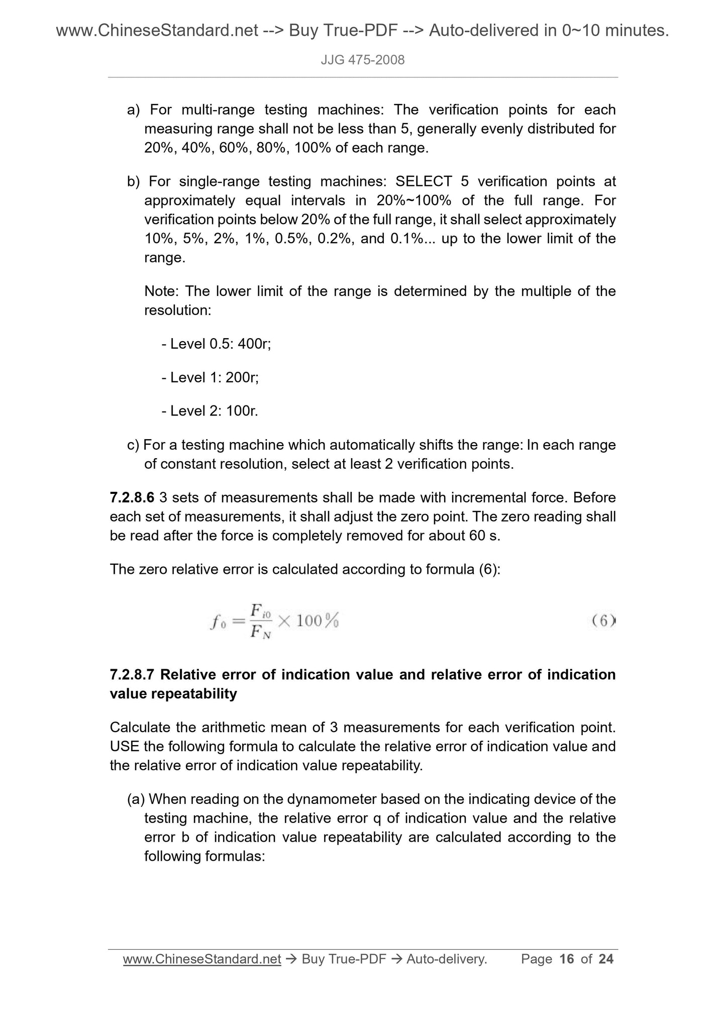
7.2.8.6 3 sets of measurements shall be made with incremental force. Before
each set of measurements, it shall adjust the zero point. The zero reading shall
be read after the force is completely removed for about 60 s.
The zero relative error is calculated according to formula (6):
7.2.8.7 Relative error of indication value and relative error of indication
value repeatability
Calculate the arithmetic mean of 3 measurements for each verification point.
USE the following formula to calculate the relative error of indication value and
the relative error of indication value repeatability.
(a) When reading on the dynamometer based on the indicating device of the
testing machine, the relative error q of indication value and the relative
error b of indication value repeatability are calculated according to the
following formulas:
7.2.10.1 START the testing machine. Within the range of applying
(102%~110%)FN test force, the safety device shall meet the requirements of
6.5.1 of this Regulation.
7.2.10.2 USE an insulation resistance measuring instrument to measure the
insulation resistance between the power cord and the casing. It shall meet the
requirements of 6.5.2 of this Regulation.
7.2.10.3 START the testing machine. When the beam reaches the set position
of its working range, the limiting device shall meet the requirements of 6.5.3 of
this Regula...
Get QUOTATION in 1-minute: Click JJG 475-2008
Historical versions: JJG 475-2008
Preview True-PDF (Reload/Scroll if blank)
JJG 475-2008: Verification Regulation of Electronic Universal Testing Machine
JJG 475-2008
NATIONAL METROLOGICAL VERIFICATION REGULATION
OF THE PEOPLE’S REPUBLIC OF CHINA
Replacing JJG 475-1986
Electronic Universal Testing Machine
ISSUED ON: JUNE 12, 2008
IMPLEMENTED ON: DECEMBER 12, 2008
Issued by: General Administration of Quality Supervision, Inspection and
Quarantine of the PRC
Verification Regulation of Electronic Universal Testing
Machine
1 Scope
This Regulation is applicable to the first verification, subsequent verification,
and in-use verification of electronic universal testing machine (hereinafter
referred to as testing machine). Type evaluation and verification of the
electronic tension (or compression) testing machine may be carried out with
reference to this Regulation.
2 References
This Regulation refers to the following documents:
GB/T 2611-1992 “General requirements for testing machines”
GB/T 16491-1996 “Electronic universal testing machines”
GB/T 16825.1-2002 “Verification of static uniaxial testing machines - Part 1:
Tension/compression testing machines - Verification and calibration of the
force-measuring system”
JJG 139-1999 “Verification Regulation of Universal Tension and
Compression Testing Machine”
JJG 762-2007 “Verification Regulation for Extensometer”
When using this Regulation, care shall be taken to use the current valid edition
of the above references.
3 Terms and units of measurement
3.1 Resolution
The ability of indicating device to meaningfully distinguish two adjacent values
of the indicated amount.
3.2 Discrimination threshold
The maximum input change which produces an imperceptible change response
installation levelness shall not exceed 0.2/1000. A space of not less than 0.7 m
shall be left around the testing machine. Its working environment shall be clean,
no vibration, no corrosive medium, and no strong electromagnetic interference.
The change in the power voltage is within ±10% of the rated voltage.
6.1.3 The electrical control of the testing machine shall be safe, reliable, and
flexible. Data measurement, transmission, calculation, display, and printing
systems shall be accurate.
6.2 Performance of testing machine
The testing machine frame shall have sufficient rigidity and test space. It shall
be able to carry out all kinds of tests conveniently and facilitate the installation
and use of sample, sample clamping device, testing machine’s accessories,
and standard dynamometer. The testing machine, during the application and
removal of forces, shall be smooth and free of shock and vibration. The
accessories of the testing machine shall comply with the requirements of GB/T
16491-1996 and related test methods.
6.3 Moving beam
6.3.1 The levelness of the moving beam shall be within 0.2/1000. The moving
beam shall be smooth when moving within the working stroke.
6.3.2 The guide members of moving beam or chuck have no significant wear or
defects.
6.3.3 The installation of the stand column and the fixed beam is not loose.
6.4 Force measuring system
6.4.1 The force measuring system shall be capable of continuously indicating
the test force applied to the sample at any time. During the application or
removal of the test force, the indication of force shall be smooth; there shall be
no shock, stagnation, or abnormal jump.
6.4.2 The testing machine shall be capable of accurately indicating and
retaining the maximum test force before the sample is broken or removed.
6.4.3 The force measuring system shall have the function of zero setting or zero
clearing.
6.4.4 The force measuring system shall generally have a calibration procedure
which facilitates verification.
6.4.5 Indicating device
7 Measuring instrument control
7.1 Verification conditions
7.1.1 Environmental conditions
The testing machine shall be verified at room temperature (10~35)°C and
relative humidity not more than 80%. The temperature fluctuation during the
verification process is not more than 2°C.
7.1.2 Standard instruments for verification
7.1.2.1 The level 0.5 testing machine is verified by using a level 0.1 standard
dynamometer or a dedicated weight with a recurrence force value error within
±0.1%. The level 1 and 2 testing-machine is verified by using a level 0.3
standard dynamometer or a dedicated weight with a recurrence force value
error within ±0.1%.
7.1.2.2 A coaxiality tester with an accuracy of ±2% (or other measuring devices
with an accuracy equivalent) or a heavy hammer.
7.1.2.3 A stopwatch with a resolution of 0.01s.
7.1.2.4 The first-order dial gauge (0.01 mm) of (0~30)mm range, the first-order
dial gauge (0.001 mm) of (0~1)mm range, and the magnetic stand; the steel
ruler with a range of 1000 mm and an error of ±0.2 mm.
7.1.2.5 A level with a division value of 0.02 mm/m.
7.1.2.6 Sound level meter (A weighting network).
7.1.2.7 Extensometer calibrator: The error of the calibrator shall not be greater
than 1/3 of the tolerance of the extensometer.
7.1.2.8 Class 10 insulation resistance measuring instrument.
7.1.2.9 Coaxiality test samples made of steel or copper and aluminum (The
gauge length is not less than 100 mm. The diameter of the gauge length is
usually not less than 10 mm. The coaxiality between the gauge length and the
two heads is φ0.02mm).
7.2 Verification items and verification methods
a) For multi-range testing machines: The verification points for each
measuring range shall not be less than 5, generally evenly distributed for
20%, 40%, 60%, 80%, 100% of each range.
b) For single-range testing machines: SELECT 5 verification points at
approximately equal intervals in 20%~100% of the full range. For
verification points below 20% of the full range, it shall select approximately
10%, 5%, 2%, 1%, 0.5%, 0.2%, and 0.1%... up to the lower limit of the
range.
Note: The lower limit of the range is determined by the multiple of the
resolution:
- Level 0.5: 400r;
- Level 1: 200r;
- Level 2: 100r.
c) For a testing machine which automatically shifts the range: In each range
of constant resolution, select at least 2 verification points.
7.2.8.6 3 sets of measurements shall be made with incremental force. Before
each set of measurements, it shall adjust the zero point. The zero reading shall
be read after the force is completely removed for about 60 s.
The zero relative error is calculated according to formula (6):
7.2.8.7 Relative error of indication value and relative error of indication
value repeatability
Calculate the arithmetic mean of 3 measurements for each verification point.
USE the following formula to calculate the relative error of indication value and
the relative error of indication value repeatability.
(a) When reading on the dynamometer based on the indicating device of the
testing machine, the relative error q of indication value and the relative
error b of indication value repeatability are calculated according to the
following formulas:
7.2.10.1 START the testing machine. Within the range of applying
(102%~110%)FN test force, the safety device shall meet the requirements of
6.5.1 of this Regulation.
7.2.10.2 USE an insulation resistance measuring instrument to measure the
insulation resistance between the power cord and the casing. It shall meet the
requirements of 6.5.2 of this Regulation.
7.2.10.3 START the testing machine. When the beam reaches the set position
of its working range, the limiting device shall meet the requirements of 6.5.3 of
this Regula...
Share