

1
/
von
5
PayPal, credit cards. Download editable-PDF & invoice in 1 second!
YY/T 0119.4-2014 English PDF (YYT0119.4-2014)
YY/T 0119.4-2014 English PDF (YYT0119.4-2014)
Normaler Preis
$150.00 USD
Normaler Preis
Verkaufspreis
$150.00 USD
Grundpreis
/
pro
Versand wird beim Checkout berechnet
Verfügbarkeit für Abholungen konnte nicht geladen werden
Delivery: 3 seconds. Download true-PDF + Invoice.
Get QUOTATION in 1-minute: Click YY/T 0119.4-2014
Historical versions: YY/T 0119.4-2014
Preview True-PDF (Reload/Scroll if blank)
YY/T 0119.4-2014: Spinal implants. Components used in the surgical fixation of the spinal skeletal system. Part4: Metallic spinal rods
YY/T 0119.4-2014
YY
PHARMACEUTICAL INDUSTRY STANDARD
OF THE PEOPLE’S REPUBLIC OF CHINA
ICS 11.040.40
C 35
Replacing YY 0120-2002
Spinal implant - Components used in the surgical
fixation of the spinal skeletal system - Part 4: Metallic
spinal rods
ISSUED ON: JUNE 17, 2014
IMPLEMENTED ON: JULY 01, 2015
Issued by: National Medical Products Administration
Table of Contents
Foreword ... 3
1 Scope ... 5
2 Normative references ... 5
3 Classification ... 5
4 Materials ... 6
5 Requirements, performance and test methods ... 6
6 Information provided by manufacturer ... 8
Annex A (informative) Basic principle ... 10
Bibliography ... 11
Spinal implant - Components used in the surgical
fixation of the spinal skeletal system - Part 4: Metallic
spinal rods
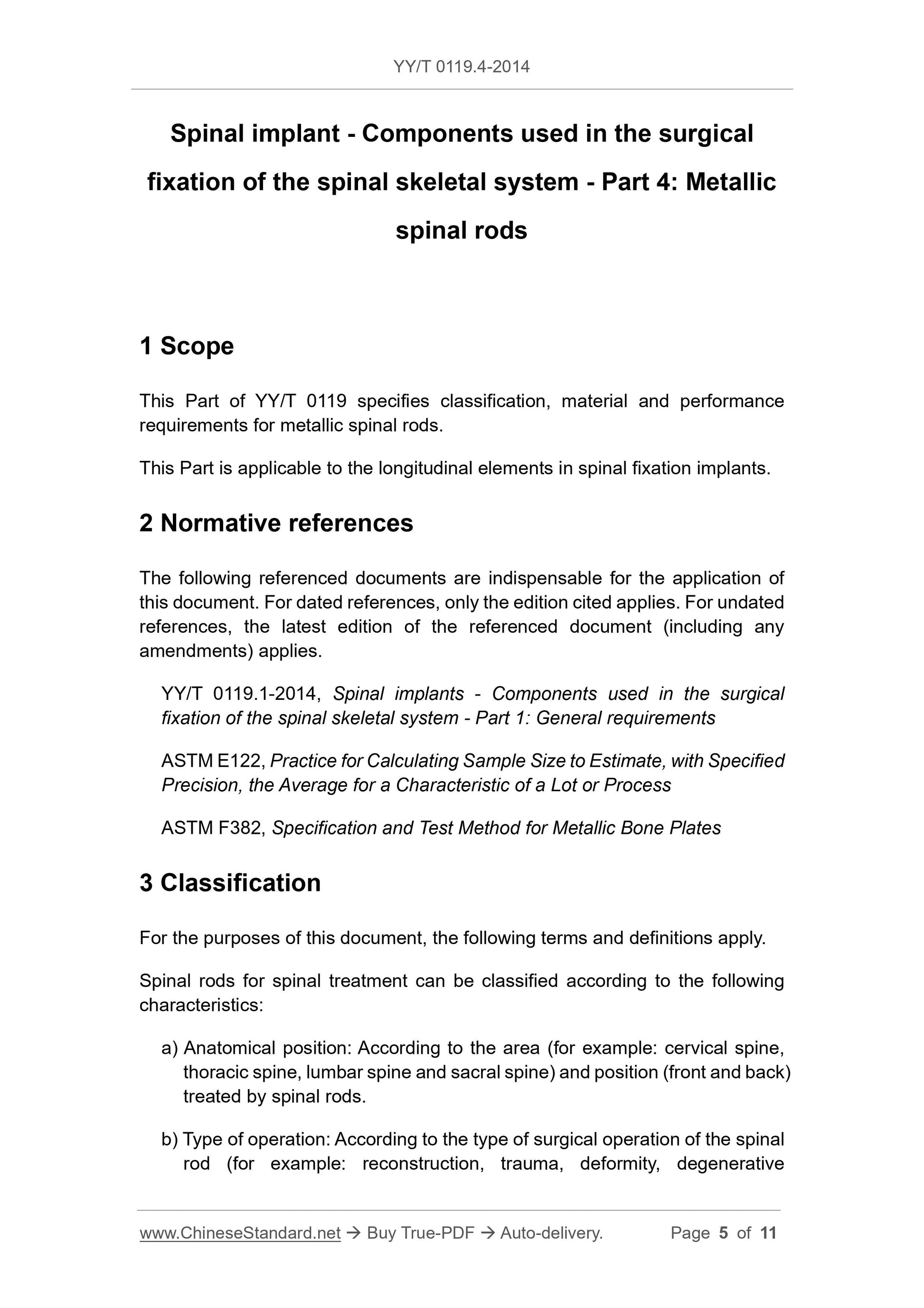
1 Scope
This Part of YY/T 0119 specifies classification, material and performance
requirements for metallic spinal rods.
This Part is applicable to the longitudinal elements in spinal fixation implants.
2 Normative references
The following referenced documents are indispensable for the application of
this document. For dated references, only the edition cited applies. For undated
references, the latest edition of the referenced document (including any
amendments) applies.
YY/T 0119.1-2014, Spinal implants - Components used in the surgical
fixation of the spinal skeletal system - Part 1: General requirements
ASTM E122, Practice for Calculating Sample Size to Estimate, with Specified
Precision, the Average for a Characteristic of a Lot or Process
ASTM F382, Specification and Test Method for Metallic Bone Plates
3 Classification
For the purposes of this document, the following terms and definitions apply.
Spinal rods for spinal treatment can be classified according to the following
characteristics:
a) Anatomical position: According to the area (for example: cervical spine,
thoracic spine, lumbar spine and sacral spine) and position (front and back)
treated by spinal rods.
b) Type of operation: According to the type of surgical operation of the spinal
rod (for example: reconstruction, trauma, deformity, degenerative
disease).
4 Materials
According to the requirements and recommendations in Chapter 5 of YY/T
0119.1-2014, select the spinal rod material.
5 Requirements, performance and test methods
5.1 Geometric characteristics
The recommended size of the metal spinal rod can be found in YY/T 0119.1.
5.2 Static test and fatigue test
5.2.1 Test requirements
Determine the bending structure stiffness, yield bending moment, ultimate
bending moment, fatigue end bending moment and median fatigue bending
moment of 2.5 million cycles of the spinal rod according to the test method in
ASTM F382 (if applicable). The test method shall meet the requirements of
5.2.2.
5.2.2 Test method
5.2.2.1 Installation method and requirements
5.2.2.1.1 Install a 90°V-groove roller shaft on the test device. The shape of the
roller allows a single set of rollers to test a range of sizes of spinal rods. These
rollers also prevent the application of loads on the maximum stress points on
the circumference of the spinal rod.
5.2.2.1.2 Install four-point bending test device to make the loading roller (the
inner roller placed on both sides of "a") be placed according to the requirements
of Table 1 (see Figure 1).
5.2.2.1.3 Place the support roller in the test device according to the
recommended size in Table 1 (the outer roller shaft is placed at a distance "h"
from the nearest roller shaft).
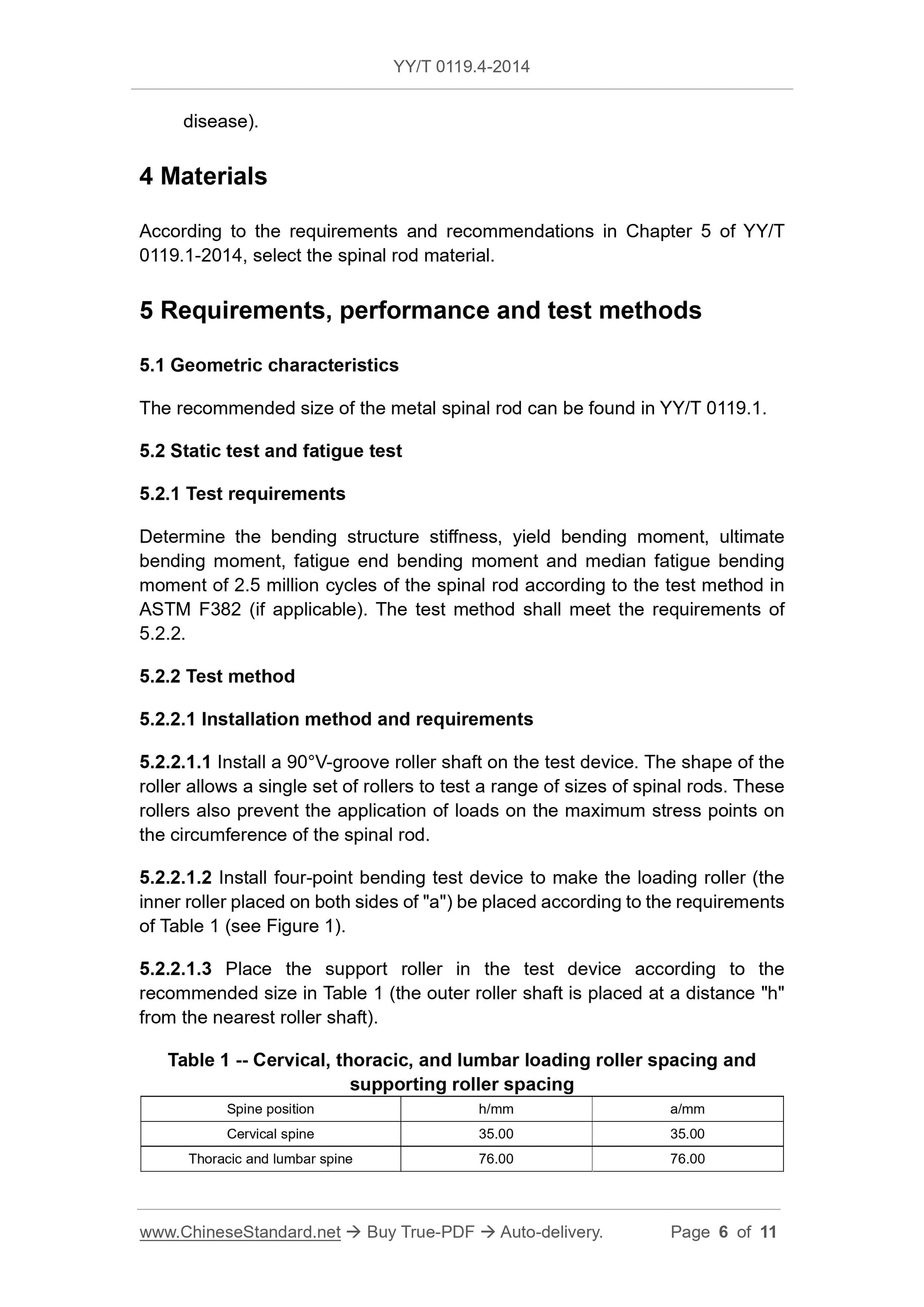
Table 1 -- Cervical, thoracic, and lumbar loading roller spacing and
supporting roller spacing
Spine position h/mm a/mm
Cervical spine 35.00 35.00
Thoracic and lumbar spine 76.00 76.00
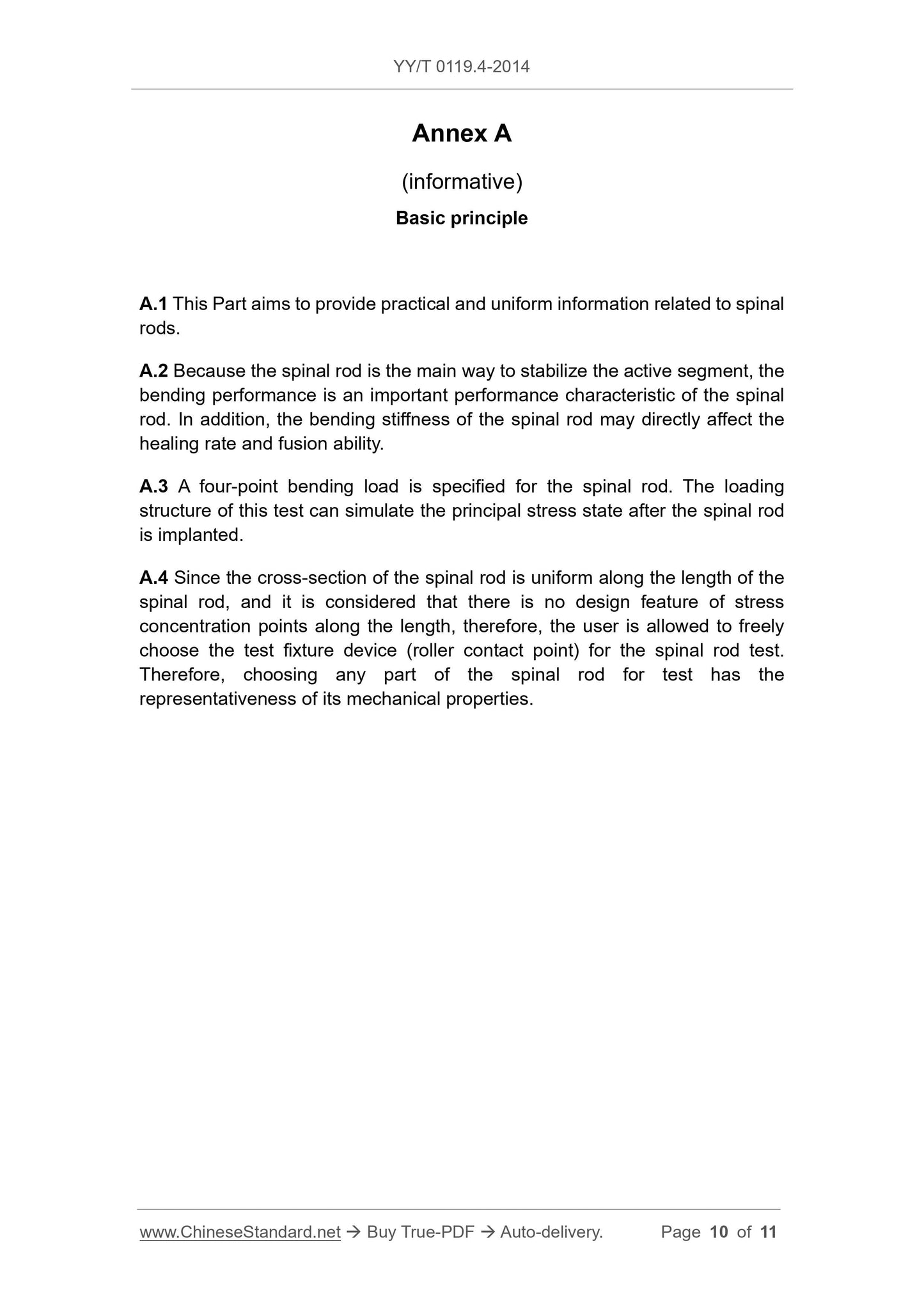
Annex A
(informative)
Basic principle
A.1 This Part aims to provide practical and uniform information related to spinal
rods.
A.2 Because the spinal rod is the main way to stabilize the active segment, the
bending performance is an important performance characteristic of the spinal
rod. In addition, the bending stiffness of the spinal rod may directly affect the
healing rate and fusion ability.
A.3 A four-point bending load is specified for the spinal rod. The loading
structure of this test can simulate the principal stress state after the spinal rod
is implanted.
A.4 Since the cross-section of the spinal rod is uniform along the length of the
spinal rod, and it is considered that there is no design feature of stress
concentration points along the length, therefore, the user is allowed to freely
choose the test fixture device (roller contact point) for the spinal rod test.
Therefore, choosing any part of the spinal rod for test has the
representativeness of its mechanical properties.
Get QUOTATION in 1-minute: Click YY/T 0119.4-2014
Historical versions: YY/T 0119.4-2014
Preview True-PDF (Reload/Scroll if blank)
YY/T 0119.4-2014: Spinal implants. Components used in the surgical fixation of the spinal skeletal system. Part4: Metallic spinal rods
YY/T 0119.4-2014
YY
PHARMACEUTICAL INDUSTRY STANDARD
OF THE PEOPLE’S REPUBLIC OF CHINA
ICS 11.040.40
C 35
Replacing YY 0120-2002
Spinal implant - Components used in the surgical
fixation of the spinal skeletal system - Part 4: Metallic
spinal rods
ISSUED ON: JUNE 17, 2014
IMPLEMENTED ON: JULY 01, 2015
Issued by: National Medical Products Administration
Table of Contents
Foreword ... 3
1 Scope ... 5
2 Normative references ... 5
3 Classification ... 5
4 Materials ... 6
5 Requirements, performance and test methods ... 6
6 Information provided by manufacturer ... 8
Annex A (informative) Basic principle ... 10
Bibliography ... 11
Spinal implant - Components used in the surgical
fixation of the spinal skeletal system - Part 4: Metallic
spinal rods
1 Scope
This Part of YY/T 0119 specifies classification, material and performance
requirements for metallic spinal rods.
This Part is applicable to the longitudinal elements in spinal fixation implants.
2 Normative references
The following referenced documents are indispensable for the application of
this document. For dated references, only the edition cited applies. For undated
references, the latest edition of the referenced document (including any
amendments) applies.
YY/T 0119.1-2014, Spinal implants - Components used in the surgical
fixation of the spinal skeletal system - Part 1: General requirements
ASTM E122, Practice for Calculating Sample Size to Estimate, with Specified
Precision, the Average for a Characteristic of a Lot or Process
ASTM F382, Specification and Test Method for Metallic Bone Plates
3 Classification
For the purposes of this document, the following terms and definitions apply.
Spinal rods for spinal treatment can be classified according to the following
characteristics:
a) Anatomical position: According to the area (for example: cervical spine,
thoracic spine, lumbar spine and sacral spine) and position (front and back)
treated by spinal rods.
b) Type of operation: According to the type of surgical operation of the spinal
rod (for example: reconstruction, trauma, deformity, degenerative
disease).
4 Materials
According to the requirements and recommendations in Chapter 5 of YY/T
0119.1-2014, select the spinal rod material.
5 Requirements, performance and test methods
5.1 Geometric characteristics
The recommended size of the metal spinal rod can be found in YY/T 0119.1.
5.2 Static test and fatigue test
5.2.1 Test requirements
Determine the bending structure stiffness, yield bending moment, ultimate
bending moment, fatigue end bending moment and median fatigue bending
moment of 2.5 million cycles of the spinal rod according to the test method in
ASTM F382 (if applicable). The test method shall meet the requirements of
5.2.2.
5.2.2 Test method
5.2.2.1 Installation method and requirements
5.2.2.1.1 Install a 90°V-groove roller shaft on the test device. The shape of the
roller allows a single set of rollers to test a range of sizes of spinal rods. These
rollers also prevent the application of loads on the maximum stress points on
the circumference of the spinal rod.
5.2.2.1.2 Install four-point bending test device to make the loading roller (the
inner roller placed on both sides of "a") be placed according to the requirements
of Table 1 (see Figure 1).
5.2.2.1.3 Place the support roller in the test device according to the
recommended size in Table 1 (the outer roller shaft is placed at a distance "h"
from the nearest roller shaft).
Table 1 -- Cervical, thoracic, and lumbar loading roller spacing and
supporting roller spacing
Spine position h/mm a/mm
Cervical spine 35.00 35.00
Thoracic and lumbar spine 76.00 76.00
Annex A
(informative)
Basic principle
A.1 This Part aims to provide practical and uniform information related to spinal
rods.
A.2 Because the spinal rod is the main way to stabilize the active segment, the
bending performance is an important performance characteristic of the spinal
rod. In addition, the bending stiffness of the spinal rod may directly affect the
healing rate and fusion ability.
A.3 A four-point bending load is specified for the spinal rod. The loading
structure of this test can simulate the principal stress state after the spinal rod
is implanted.
A.4 Since the cross-section of the spinal rod is uniform along the length of the
spinal rod, and it is considered that there is no design feature of stress
concentration points along the length, therefore, the user is allowed to freely
choose the test fixture device (roller contact point) for the spinal rod test.
Therefore, choosing any part of the spinal rod for test has the
representativeness of its mechanical properties.
Share