PayPal, credit cards. Download editable-PDF and invoice in 1 second!
DL/T 437-2012 English PDF (DLT437-2012)
DL/T 437-2012 English PDF (DLT437-2012)
Precio habitual
$190.00 USD
Precio habitual
Precio de oferta
$190.00 USD
Precio unitario
/
por
Los gastos de envío se calculan en la pantalla de pago.
No se pudo cargar la disponibilidad de retiro
Delivery: 3 seconds. Download true-PDF + Invoice.
Get QUOTATION in 1-minute: Click DL/T 437-2012
Historical versions: DL/T 437-2012
Preview True-PDF (Reload/Scroll if blank)
DL/T 437-2012: Technical guide of HVDC earth electrode system
DL/T 437-2012
DL
ELECTRIC POWER INDUSTRY STANDARD
OF THE PEOPLE’S REPUBLIC OF CHINA
ICS 29.240
F 21
Record number: 35213-2012
Replacing DL/T 437-1991
Technical guide of HVDC earth electrode system
ISSUED ON: JANUARY 04, 2012
IMPLEMENTED ON: MARCH 01, 2012
Issued by: National Energy Administration
Table of Contents
Foreword ... 3
1 Scope ... 4
2 Normative references ... 4
3 Terms and definitions ... 4
4 Technical conditions ... 7
5 Test ... 12
6 Assessment and protection of the impact on surrounding facilities ... 16
7 Operation and maintenance of DC earth electrode ... 16
Appendix A (Informative) Unequal-distance quadrupole method for measuring
the resistivity of deep earth ... 19
Appendix B (Normative) Thermal conductivity, heat capacity rate and coke
requirements ... 20
Appendix C (Informative) Maximum allowable step potential on the ground .. 21
Technical guide of HVDC earth electrode system
1 Scope
This Standard specifies the terminology terms and definitions of HVDC earth
electrode system, and proposes technical conditions, test items and methods,
and general technical principles of operation and maintenance.
This Standard applies to the earth electrode system at both ends of the
monopolar and bipolar HVDC transmission system; it does not apply to the
converter grounding grid.
2 Normative references
The following documents are indispensable for the application of this document.
For dated references, only the dated version applies to this document. For
undated references, the latest edition (including all amendments) applies to this
document.
GB/T 17949.1, Guide for measuring earth resistivity, ground impedance and
earth surface potentials of a ground system - Part 1: Normal measurements
GB/T 13498, Terminology for high-voltage direct current (HVDC)
transmission
DL/T 5224, Technical Rule for the Design of HVDC Earth Return Operation
System
DL/T 475, Guide for measurement of grounding connection parameters
3 Terms and definitions
Except for the terms which are specified in this Chapter, the rest shall be in
compliance with the relevant provisions of national and industry standards.
3.1
HVDC earth electrode system
The general term for a group of devices that are specially designed and
constructed to operate with earth or sea water as a current loop during normal
operation or failure, in the high-voltage direct current transmission system. It is
mainly composed of an electrode line, an earth electrode feeder line and an
earth electrode.
When the earth electrode is in operation, if a person stands on the ground near
the earth electrode and touches an earth conductor that is connected from a
remote place, or if a person stands on the distant ground and touches an earth
conductor that is drawn from a place near the electrode site grounding, the
touch potential it bears is the transfer potential. The maximum value of the
transfer potential is the earthing electrode potential rise.
4 Technical conditions
4.1 General technical guidelines
4.1.1 The design of the DC earth electrode shall consider the three working
conditions of rated current under monopolar mode, maximum overload current
and maximum transient overcurrents.
4.1.2 The design life of the DC earth electrode shall generally be no less than
30 years under the specified operation mode.
4.1.3 The DC earth electrode is generally composed of 2 or more separated
components.
4.1.4 In order to prevent the earth current of the HVDC earth electrode system
from corroding and interfering with the converter station, the straight-line
distance between the earth electrode and the converter station in the HVDC
transmission system should not be less than 10 km; it shall be ensured that the
grounding grid of the converter station is completely separated from the earth
electrode.
4.1.5 The DC earth electrode generally has ring, star, linear, ray, grid shapes,
which should be confirmed according to the conditions of the electrode site
topography, geology, hydrology, traffic conditions, from the two aspects of
convenient construction and reasonable technology and economy.
4.1.6 The buried depth of the DC earth electrode shall be determined, according
to the requirements for step potential in this Standard, by comprehensive
techno-economic comparison in combination with the soil climate
characteristics of the electrode site, the engineering excavation and the
external force factors; it is generally not less than 1.5 m.
4.1.7 The earth electrode design shall consider the changes of the groundwater
level; water injection devices shall be installed when necessary.
4.2 Electrode site selection
4.2.1 The DC earth electrode site should generally be far away from densely
populated cities and towns, and areas with more public facilities underground.
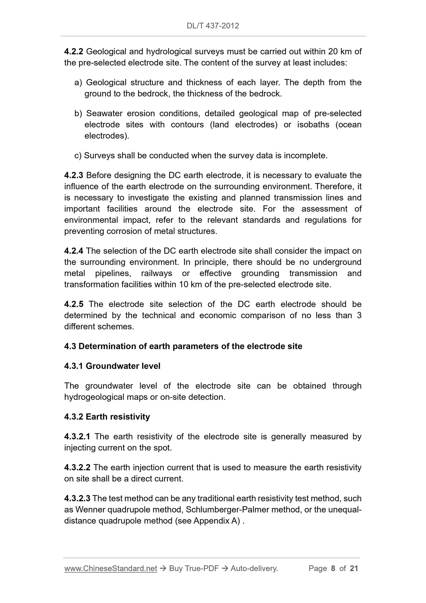
4.2.2 Geological and hydrological surveys must be carried out within 20 km of
the pre-selected electrode site. The content of the survey at least includes:
a) Geological structure and thickness of each layer. The depth from the
ground to the bedrock, the thickness of the bedrock.
b) Seawater erosion conditions, detailed geological map of pre-selected
electrode sites with contours (land electrodes) or isobaths (ocean
electrodes).
c) Surveys shall be conducted when the survey data is incomplete.
4.2.3 Before designing the DC earth electrode, it is necessary to evaluate the
influence of the earth electrode on the surrounding environment. Therefore, it
is necessary to investigate the existing and planned transmission lines and
important facilities around the electrode site. For the assessment of
environmental impact, refer to the relevant standards and regulations for
preventing corrosion of metal structures.
4.2.4 The selection of the DC earth electrode site shall consider the impact on
the surrounding environment. In principle, there should be no underground
metal pipelines, railways or effective grounding transmission and
transformation facilities within 10 km of the pre-selected electrode site.
4.2.5 The electrode site selection of the DC earth electrode should be
determined by the technical and economic comparison of no less than 3
different schemes.
4.3 Determination of earth parameters of the electrode site
4.3.1 Groundwater level
The groundwater level of the electrode site can be obtained through
hydrogeological maps or on-site detection.
4.3.2 Earth resistivity
4.3.2.1 The earth resistivity of the electrode site is generally measured by
injecting current on the spot.
4.3.2.2 The earth injection current that is used to measure the earth resistivity
on site shall be a direct current.
4.3.2.3 The test method can be any traditional earth resistivity test method, such
as Wenner quadrupole method, Schlumberger-Palmer method, or the unequal-
distance quadrupole method (see Appendix A) .
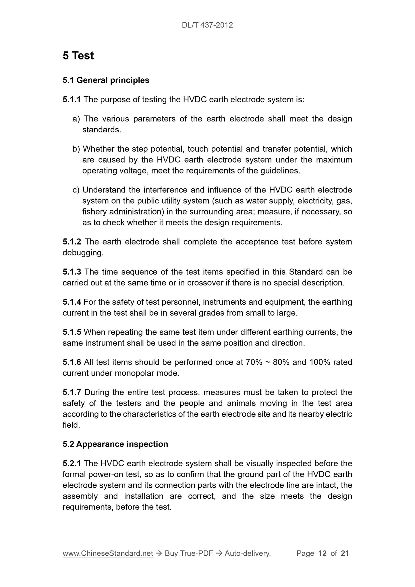
5 Test
5.1 General principles
5.1.1 The purpose of testing the HVDC earth electrode system is:
a) The various parameters of the earth electrode shall meet the design
standards.
b) Whether the step potential, touch potential and transfer potential, which
are caused by the HVDC earth electrode system under the maximum
operating voltage, meet the requirements of the guidelines.
c) Understand the interference and influence of the HVDC earth electrode
system on the public utility system (such as water supply, electricity, gas,
fishery...
Get QUOTATION in 1-minute: Click DL/T 437-2012
Historical versions: DL/T 437-2012
Preview True-PDF (Reload/Scroll if blank)
DL/T 437-2012: Technical guide of HVDC earth electrode system
DL/T 437-2012
DL
ELECTRIC POWER INDUSTRY STANDARD
OF THE PEOPLE’S REPUBLIC OF CHINA
ICS 29.240
F 21
Record number: 35213-2012
Replacing DL/T 437-1991
Technical guide of HVDC earth electrode system
ISSUED ON: JANUARY 04, 2012
IMPLEMENTED ON: MARCH 01, 2012
Issued by: National Energy Administration
Table of Contents
Foreword ... 3
1 Scope ... 4
2 Normative references ... 4
3 Terms and definitions ... 4
4 Technical conditions ... 7
5 Test ... 12
6 Assessment and protection of the impact on surrounding facilities ... 16
7 Operation and maintenance of DC earth electrode ... 16
Appendix A (Informative) Unequal-distance quadrupole method for measuring
the resistivity of deep earth ... 19
Appendix B (Normative) Thermal conductivity, heat capacity rate and coke
requirements ... 20
Appendix C (Informative) Maximum allowable step potential on the ground .. 21
Technical guide of HVDC earth electrode system
1 Scope
This Standard specifies the terminology terms and definitions of HVDC earth
electrode system, and proposes technical conditions, test items and methods,
and general technical principles of operation and maintenance.
This Standard applies to the earth electrode system at both ends of the
monopolar and bipolar HVDC transmission system; it does not apply to the
converter grounding grid.
2 Normative references
The following documents are indispensable for the application of this document.
For dated references, only the dated version applies to this document. For
undated references, the latest edition (including all amendments) applies to this
document.
GB/T 17949.1, Guide for measuring earth resistivity, ground impedance and
earth surface potentials of a ground system - Part 1: Normal measurements
GB/T 13498, Terminology for high-voltage direct current (HVDC)
transmission
DL/T 5224, Technical Rule for the Design of HVDC Earth Return Operation
System
DL/T 475, Guide for measurement of grounding connection parameters
3 Terms and definitions
Except for the terms which are specified in this Chapter, the rest shall be in
compliance with the relevant provisions of national and industry standards.
3.1
HVDC earth electrode system
The general term for a group of devices that are specially designed and
constructed to operate with earth or sea water as a current loop during normal
operation or failure, in the high-voltage direct current transmission system. It is
mainly composed of an electrode line, an earth electrode feeder line and an
earth electrode.
When the earth electrode is in operation, if a person stands on the ground near
the earth electrode and touches an earth conductor that is connected from a
remote place, or if a person stands on the distant ground and touches an earth
conductor that is drawn from a place near the electrode site grounding, the
touch potential it bears is the transfer potential. The maximum value of the
transfer potential is the earthing electrode potential rise.
4 Technical conditions
4.1 General technical guidelines
4.1.1 The design of the DC earth electrode shall consider the three working
conditions of rated current under monopolar mode, maximum overload current
and maximum transient overcurrents.
4.1.2 The design life of the DC earth electrode shall generally be no less than
30 years under the specified operation mode.
4.1.3 The DC earth electrode is generally composed of 2 or more separated
components.
4.1.4 In order to prevent the earth current of the HVDC earth electrode system
from corroding and interfering with the converter station, the straight-line
distance between the earth electrode and the converter station in the HVDC
transmission system should not be less than 10 km; it shall be ensured that the
grounding grid of the converter station is completely separated from the earth
electrode.
4.1.5 The DC earth electrode generally has ring, star, linear, ray, grid shapes,
which should be confirmed according to the conditions of the electrode site
topography, geology, hydrology, traffic conditions, from the two aspects of
convenient construction and reasonable technology and economy.
4.1.6 The buried depth of the DC earth electrode shall be determined, according
to the requirements for step potential in this Standard, by comprehensive
techno-economic comparison in combination with the soil climate
characteristics of the electrode site, the engineering excavation and the
external force factors; it is generally not less than 1.5 m.
4.1.7 The earth electrode design shall consider the changes of the groundwater
level; water injection devices shall be installed when necessary.
4.2 Electrode site selection
4.2.1 The DC earth electrode site should generally be far away from densely
populated cities and towns, and areas with more public facilities underground.
4.2.2 Geological and hydrological surveys must be carried out within 20 km of
the pre-selected electrode site. The content of the survey at least includes:
a) Geological structure and thickness of each layer. The depth from the
ground to the bedrock, the thickness of the bedrock.
b) Seawater erosion conditions, detailed geological map of pre-selected
electrode sites with contours (land electrodes) or isobaths (ocean
electrodes).
c) Surveys shall be conducted when the survey data is incomplete.
4.2.3 Before designing the DC earth electrode, it is necessary to evaluate the
influence of the earth electrode on the surrounding environment. Therefore, it
is necessary to investigate the existing and planned transmission lines and
important facilities around the electrode site. For the assessment of
environmental impact, refer to the relevant standards and regulations for
preventing corrosion of metal structures.
4.2.4 The selection of the DC earth electrode site shall consider the impact on
the surrounding environment. In principle, there should be no underground
metal pipelines, railways or effective grounding transmission and
transformation facilities within 10 km of the pre-selected electrode site.
4.2.5 The electrode site selection of the DC earth electrode should be
determined by the technical and economic comparison of no less than 3
different schemes.
4.3 Determination of earth parameters of the electrode site
4.3.1 Groundwater level
The groundwater level of the electrode site can be obtained through
hydrogeological maps or on-site detection.
4.3.2 Earth resistivity
4.3.2.1 The earth resistivity of the electrode site is generally measured by
injecting current on the spot.
4.3.2.2 The earth injection current that is used to measure the earth resistivity
on site shall be a direct current.
4.3.2.3 The test method can be any traditional earth resistivity test method, such
as Wenner quadrupole method, Schlumberger-Palmer method, or the unequal-
distance quadrupole method (see Appendix A) .
5 Test
5.1 General principles
5.1.1 The purpose of testing the HVDC earth electrode system is:
a) The various parameters of the earth electrode shall meet the design
standards.
b) Whether the step potential, touch potential and transfer potential, which
are caused by the HVDC earth electrode system under the maximum
operating voltage, meet the requirements of the guidelines.
c) Understand the interference and influence of the HVDC earth electrode
system on the public utility system (such as water supply, electricity, gas,
fishery...
Share