PayPal, credit cards. Download editable-PDF & invoice in 1 second!
GB 14050-2008 English PDF (GB14050-2008)
GB 14050-2008 English PDF (GB14050-2008)
Precio habitual
$85.00 USD
Precio habitual
Precio de oferta
$85.00 USD
Precio unitario
/
por
Los gastos de envío se calculan en la pantalla de pago.
No se pudo cargar la disponibilidad de retiro
Delivery: 3 seconds. Download true-PDF + Invoice.
Get QUOTATION in 1-minute: Click GB 14050-2008
Historical versions: GB 14050-2008
Preview True-PDF (Reload/Scroll if blank)
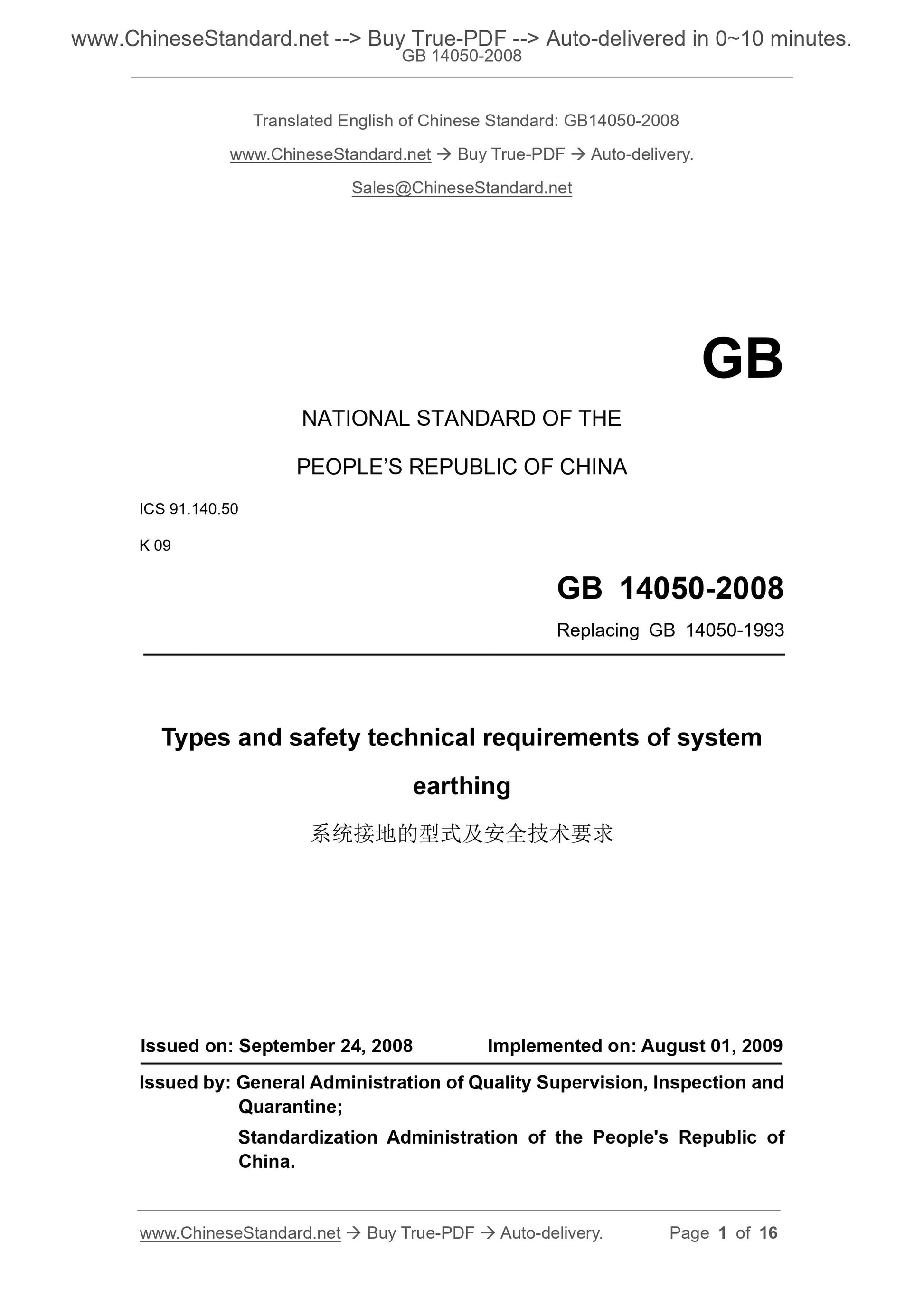
GB 14050-2008: Types and safety technical requirements of system earthing
GB 14050-2008
NATIONAL STANDARD OF THE
PEOPLE’S REPUBLIC OF CHINA
ICS 91.140.50
K 09
Replacing GB 14050-1993
Types and safety technical requirements of system
earthing
ISSUED ON: SEPTEMBER 24, 2008
IMPLEMENTED ON: AUGUST 01, 2009
Issued by: General Administration of Quality Supervision, Inspection and
Quarantine;
Standardization Administration of the People's Republic of
China.
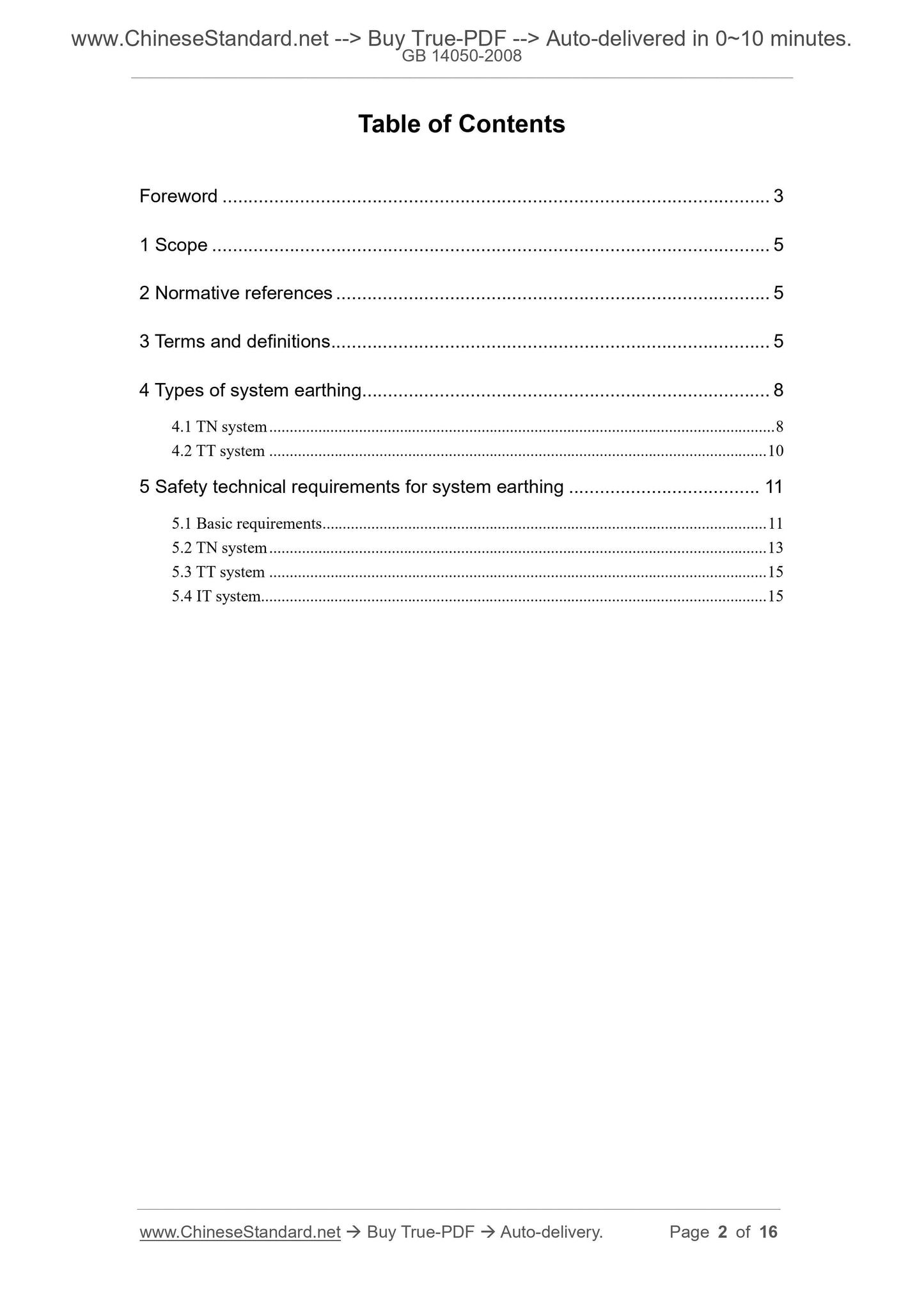
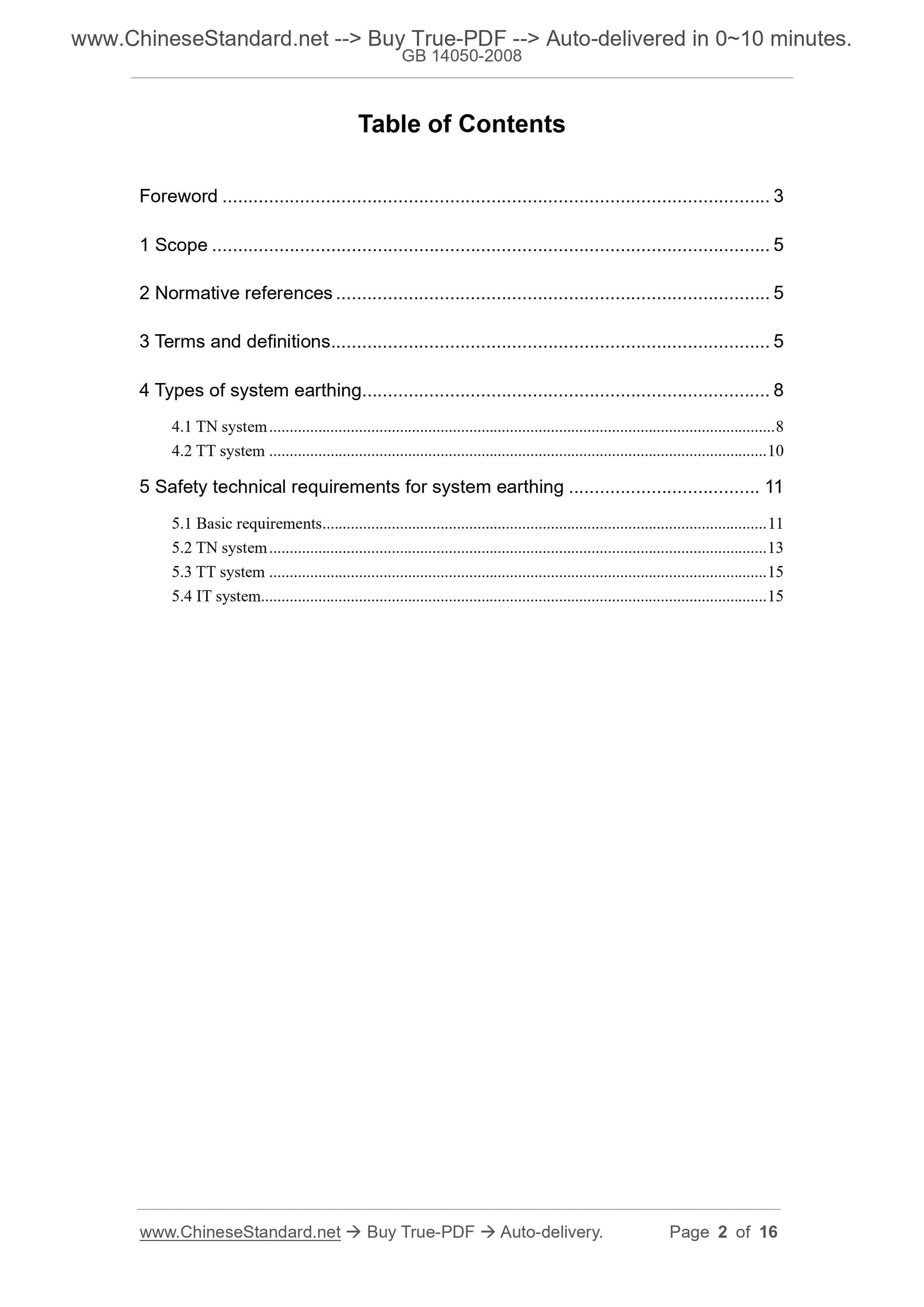
Table of Contents
Foreword ... 3
1 Scope ... 5
2 Normative references ... 5
3 Terms and definitions ... 5
4 Types of system earthing ... 8
4.1 TN system ... 8
4.2 TT system ... 10
5 Safety technical requirements for system earthing ... 11
5.1 Basic requirements ... 11
5.2 TN system ... 13
5.3 TT system ... 15
5.4 IT system ... 15
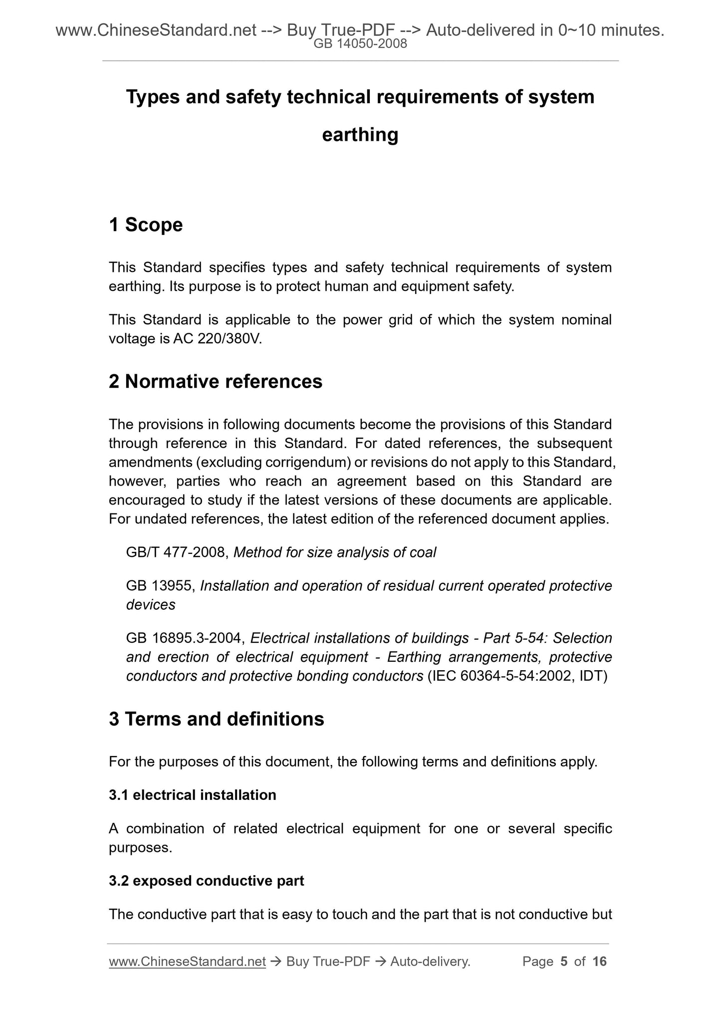
Types and safety technical requirements of system
earthing
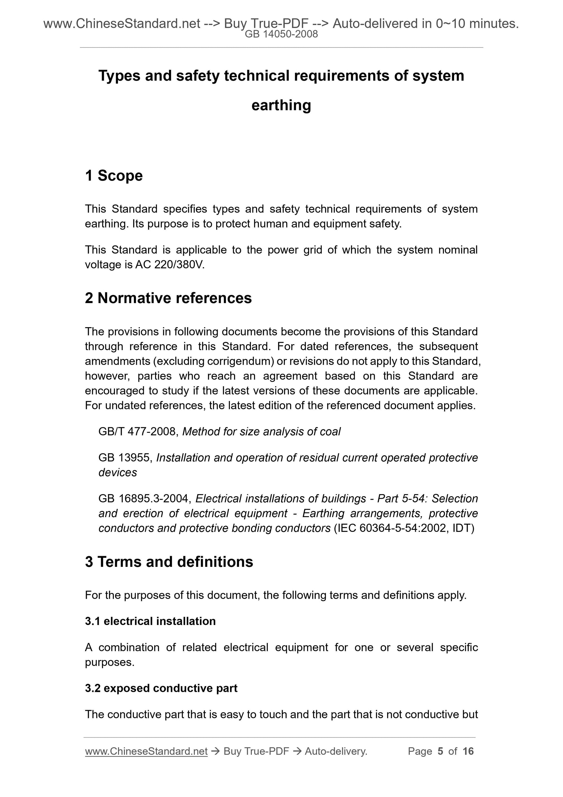
1 Scope
This Standard specifies types and safety technical requirements of system
earthing. Its purpose is to protect human and equipment safety.
This Standard is applicable to the power grid of which the system nominal
voltage is AC 220/380V.
2 Normative references
The provisions in following documents become the provisions of this Standard
through reference in this Standard. For dated references, the subsequent
amendments (excluding corrigendum) or revisions do not apply to this Standard,
however, parties who reach an agreement based on this Standard are
encouraged to study if the latest versions of these documents are applicable.
For undated references, the latest edition of the referenced document applies.
GB/T 477-2008, Method for size analysis of coal
GB 13955, Installation and operation of residual current operated protective
devices
GB 16895.3-2004, Electrical installations of buildings - Part 5-54: Selection
and erection of electrical equipment - Earthing arrangements, protective
conductors and protective bonding conductors (IEC 60364-5-54:2002, IDT)
3 Terms and definitions
For the purposes of this document, the following terms and definitions apply.
3.1 electrical installation
A combination of related electrical equipment for one or several specific
purposes.
3.2 exposed conductive part
The conductive part that is easy to touch and the part that is not conductive but
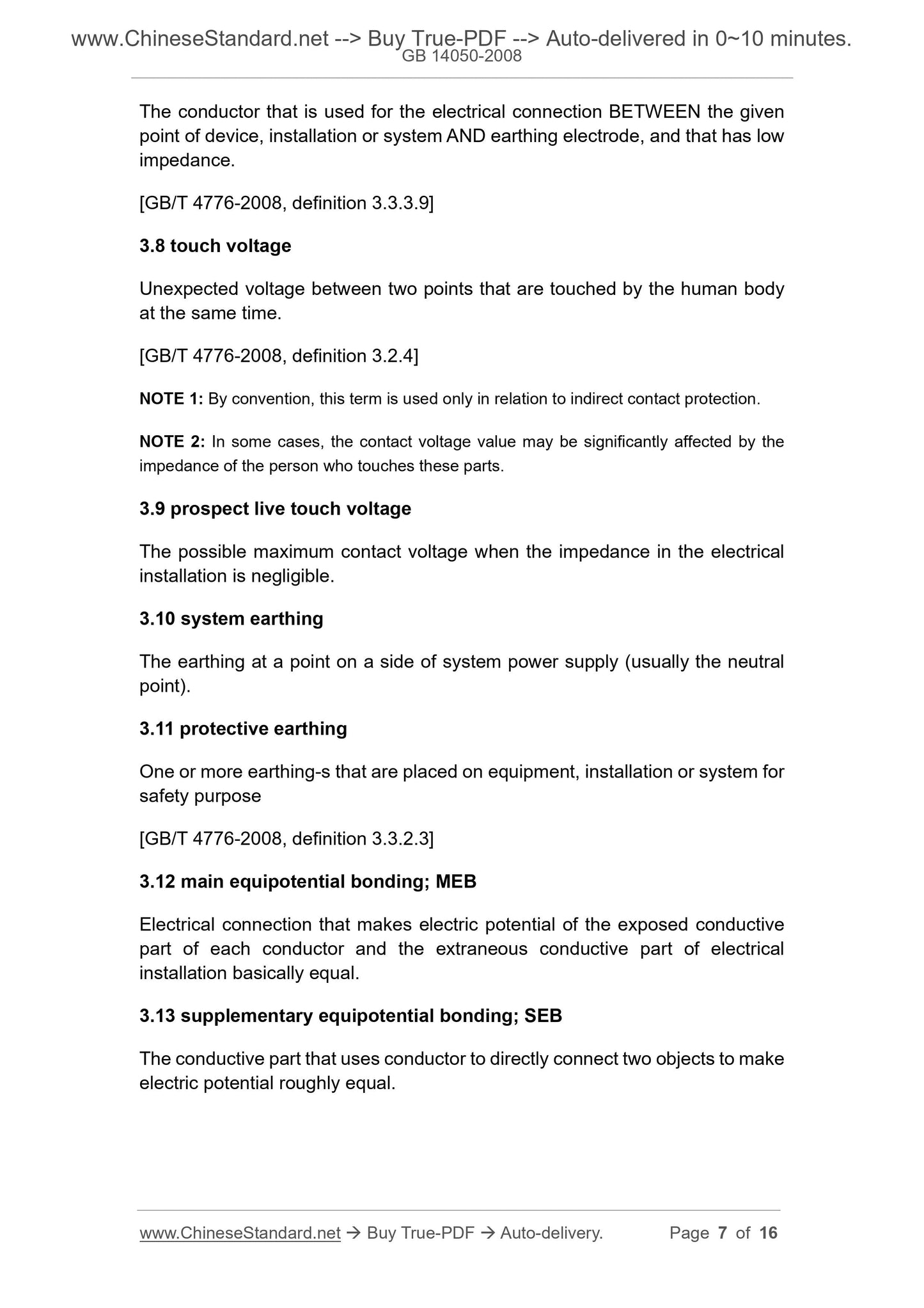
The conductor that is used for the electrical connection BETWEEN the given
point of device, installation or system AND earthing electrode, and that has low
impedance.
[GB/T 4776-2008, definition 3.3.3.9]
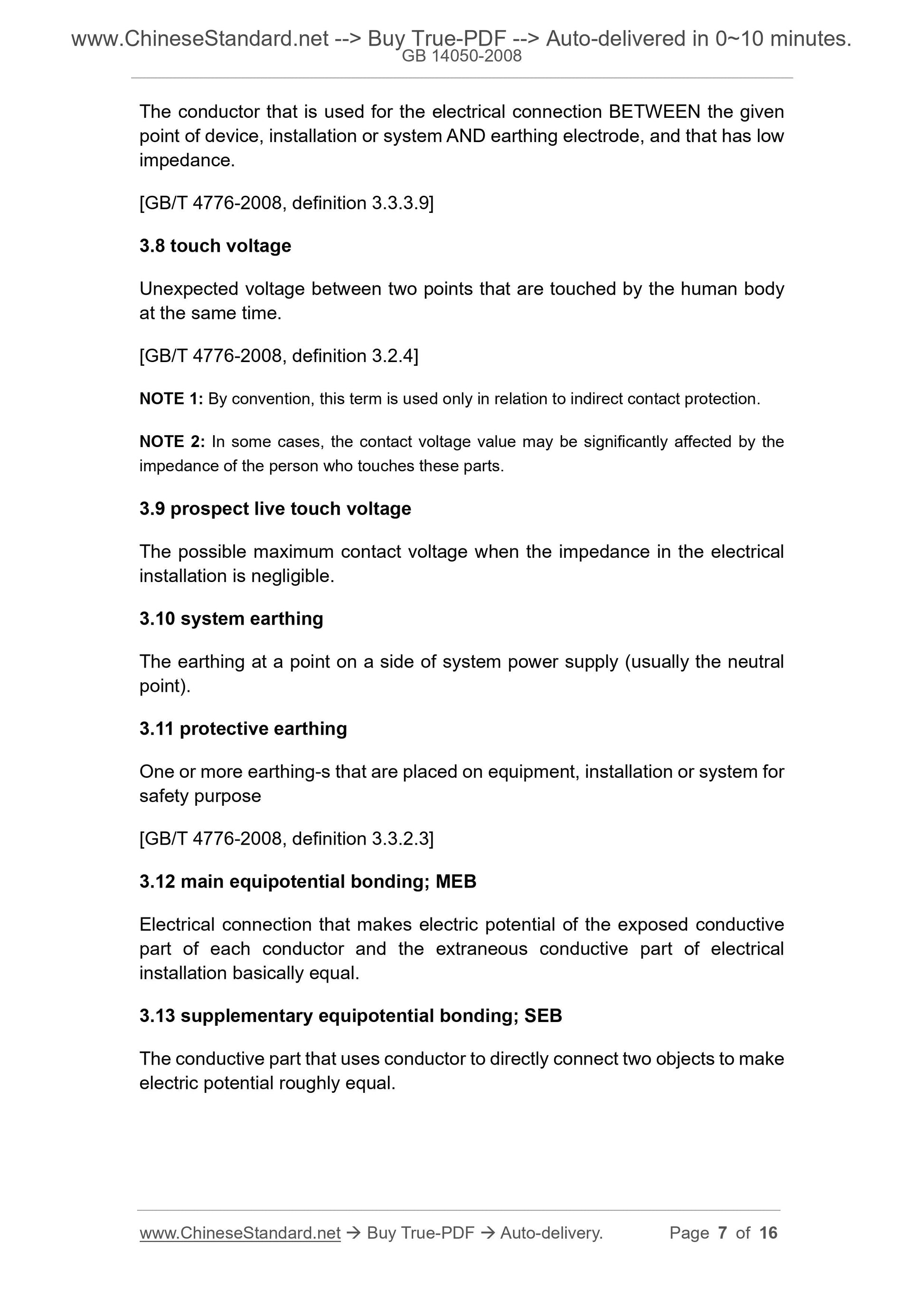
3.8 touch voltage
Unexpected voltage between two points that are touched by the human body
at the same time.
[GB/T 4776-2008, definition 3.2.4]
NOTE 1: By convention, this term is used only in relation to indirect contact protection.
NOTE 2: In some cases, the contact voltage value may be significantly affected by the
impedance of the person who touches these parts.
3.9 prospect live touch voltage
The possible maximum contact voltage when the impedance in the electrical
installation is negligible.
3.10 system earthing
The earthing at a point on a side of system power supply (usually the neutral
point).
3.11 protective earthing
One or more earthing-s that are placed on equipment, installation or system for
safety purpose
[GB/T 4776-2008, definition 3.3.2.3]
3.12 main equipotential bonding; MEB
Electrical connection that makes electric potential of the exposed conductive
part of each conductor and the extraneous conductive part of electrical
installation basically equal.
3.13 supplementary equipotential bonding; SEB
The conductive part that uses conductor to directly connect two objects to make
electric potential roughly equal.
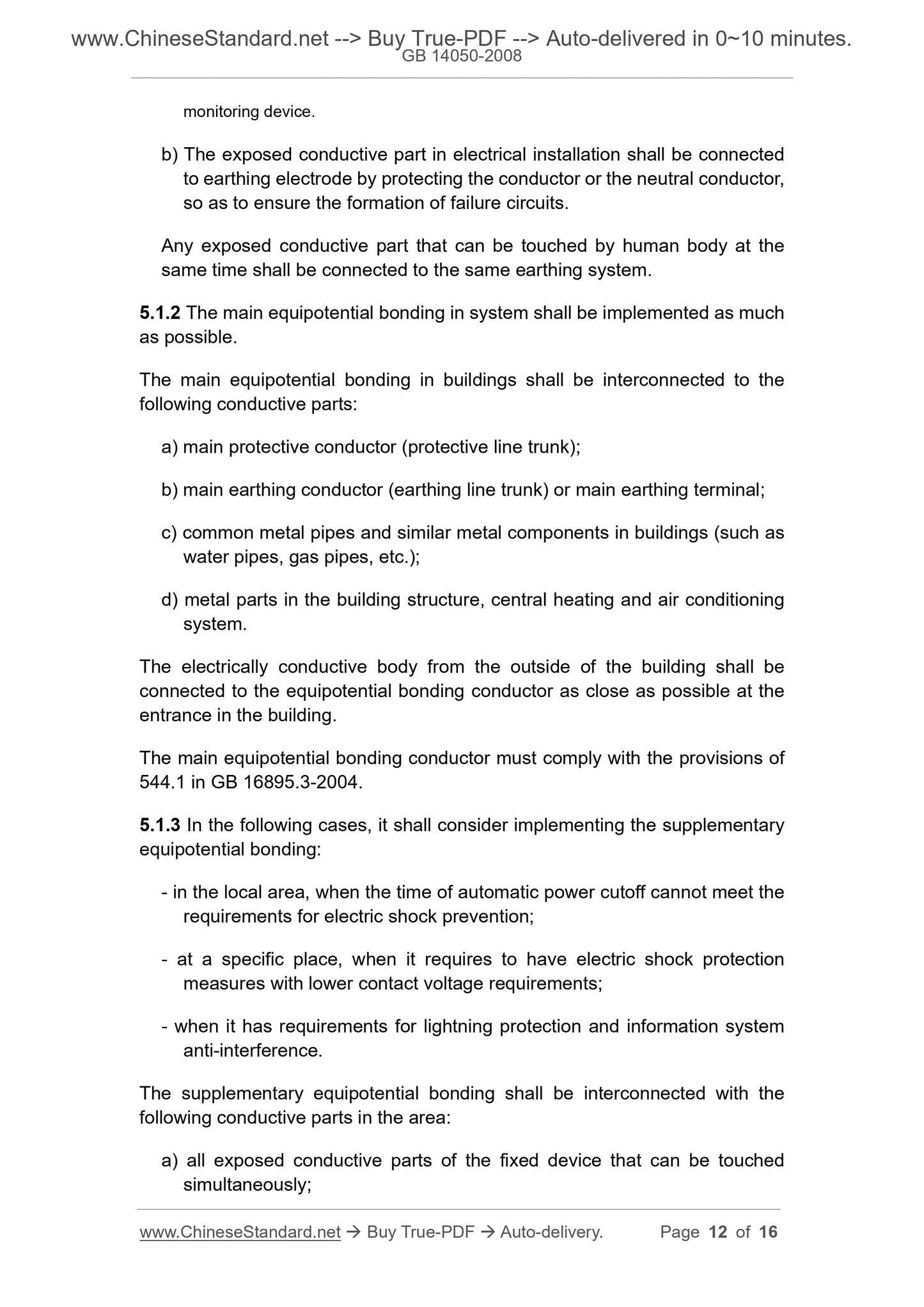
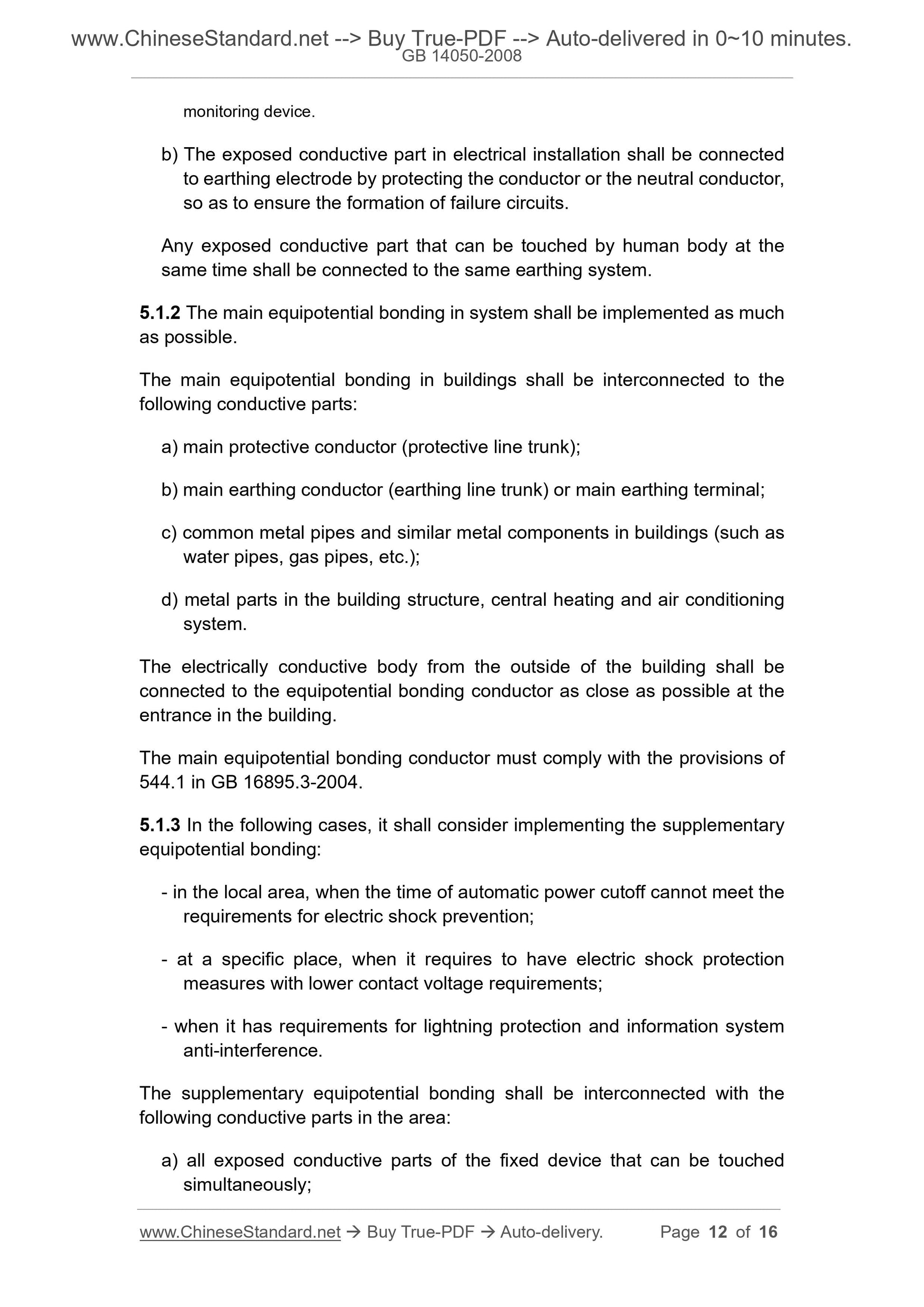
monitoring device.
b) The exposed conductive part in electrical installation shall be connected
to earthing electrode by protecting the conductor or the neutral conductor,
so as to ensure the formation of failure circuits.
Any exposed conductive part that can be touched by human body at the
same time shall be connected to the same earthing system.
5.1.2 The main equipotential bonding in system shall be implemented as much
as possible.
The main equipotential bonding in buildings shall be interconnected to the
following conductive parts:
a) main protective conductor (protective line trunk);
b) main earthing conductor (earthing line trunk) or main earthing terminal;
c) common metal pipes and similar metal components in buildings (such as
water pipes, gas pipes, etc.);
d) metal parts in the building structure, central heating and air conditioning
system.
The electrically conductive body from the outside of the building shall be
connected to the equipotential bonding conductor as close as possible at the
entrance in the building.
The main equipotential bonding conductor must comply with the provisions of
544.1 in GB 16895.3-2004.
5.1.3 In the following cases, it shall consider implementing the supplementary
equipotential bonding:
- in the local area, when the time of automatic power cutoff cannot meet the
requirements for electric shock prevention;
- at a specific place, when it requires to have electric shock protection
measures with lower contact voltage requirements;
- when it has requirements for lightning protection and information system
anti-interference.
The supplementary equipotential bonding shall be interconnected with the
following conductive parts in the area:
a) all exposed conductive parts of the fixed device that can be touched
simultaneously;
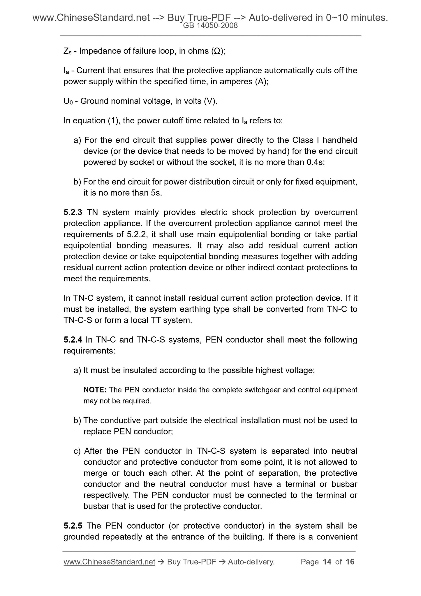
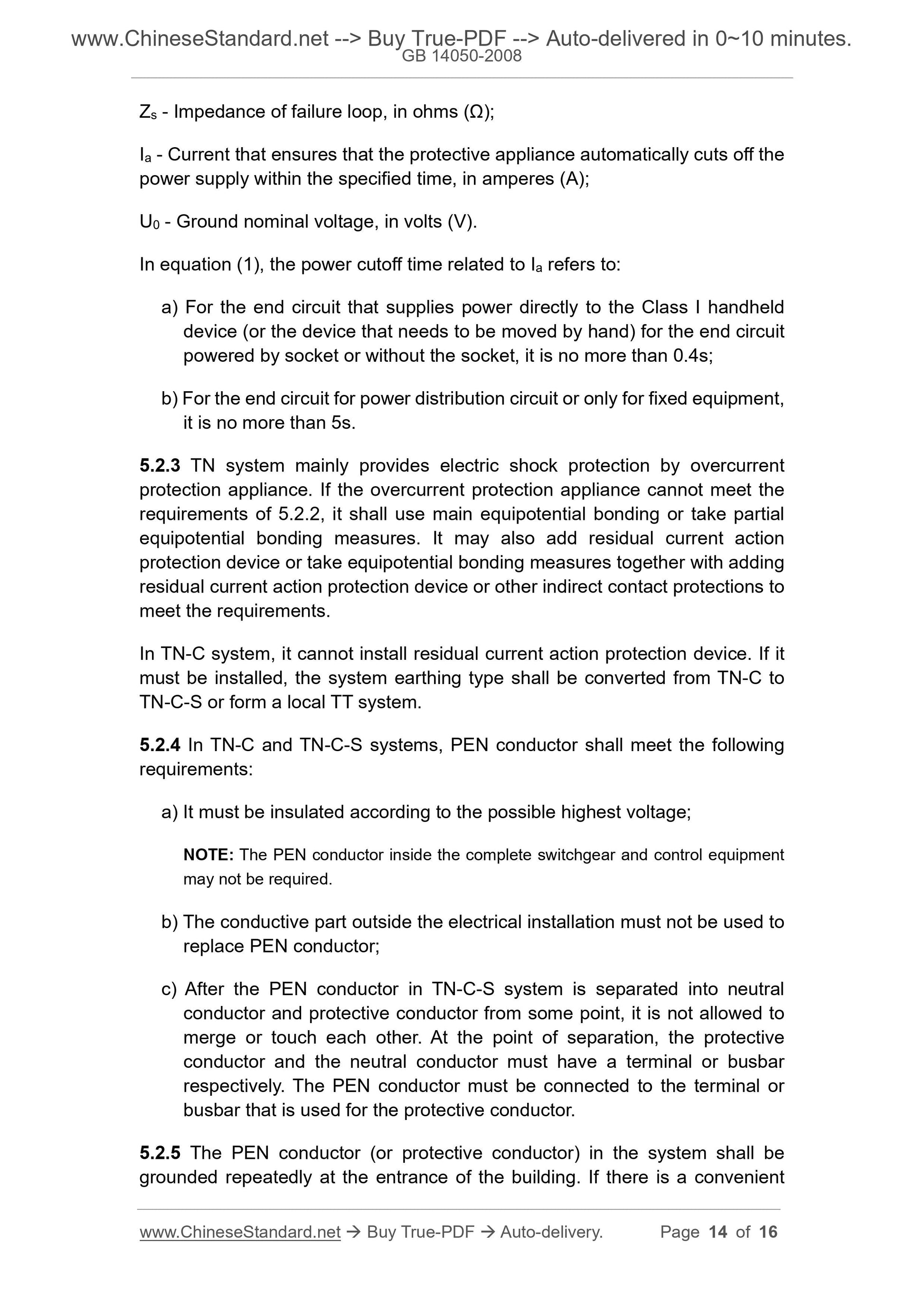
Zs - Impedance of failure loop, in ohms (Ω);
Ia - Current that ensures that the protective appliance automatically cuts off the
power supply within the specified time, in amperes (A);
U0 - Ground nominal voltage, in volts (V).
In equation (1), the power cutoff time related to Ia refers to:
a) For the end circuit that supplies power directly to the Class I handheld
device (or the device that needs to be moved by hand) for the end circuit
powered by socket or without the socket, it is no more than 0.4s;
b) For the end circuit for power distribution circuit or only for fixed equipment,
it is no more than 5s.
5.2.3 TN system mainly provides electric shock protection by overcurrent
protection appliance. If the overcurrent protection appliance cannot meet the
requirements of 5.2.2, it shall use main equipotential bonding or take partial
equipotential bonding measures. It may also add residual current action
protection device or take equipotential bonding measures together with adding
residual current action protection device or other indirect contact protections to
meet the requirements.
In TN-C system, it cannot install residual current action protection device. If it
must be installed, the system earthing type shall be converted from TN-C to
TN-C-S or form a local TT system.
5.2.4 In TN-C and TN-C-S systems, PEN conductor shall meet the following
requirements:
a) It must be insulated according to the possible highest voltage;
NOTE: The PEN conductor inside the complete switchgear and control equipment
may not be required.
b) The conductive part outside the electrical installation must not be used to
replace PEN conductor;
c) After the PEN conductor in TN-C-S system is separated into neutral
conductor and protective conductor from some point, it is not allowed to
merge or touch each other. At the point of separation, the protective
conductor and the neutral conductor must have a terminal or busbar
respectively. The PEN condu...
Share
