PayPal, credit cards. Download editable-PDF and invoice in 1 second!
GB/T 11982.1-2015 English PDF (GBT11982.1-2015)
GB/T 11982.1-2015 English PDF (GBT11982.1-2015)
Precio habitual
$270.00 USD
Precio habitual
Precio de oferta
$270.00 USD
Precio unitario
/
por
Los gastos de envío se calculan en la pantalla de pago.
No se pudo cargar la disponibilidad de retiro
Delivery: 3 seconds. Download true-PDF + Invoice.
Get QUOTATION in 1-minute: Click GB/T 11982.1-2015
Historical versions: GB/T 11982.1-2015
Preview True-PDF (Reload/Scroll if blank)
GB/T 11982.1-2015: Polyvinyl chloride floor coverings -- Part 1: Heterogeneous polyvinyl chloride floor coverings
GB/T 11982.1-2015
NATIONAL STANDARD OF THE
PEOPLE’S REPUBLIC OF CHINA
ICS 83.140
Q 22
Replacing GB/T 11982.1-2005
Polyvinyl chloride floor coverings - Part 1:
Heterogeneous polyvinyl chloride floor coverings
聚氯乙烯卷材地板
ISSUED ON: SEPTEMBER 11, 2015
IMPLEMENTED ON: AUGUST 01, 2016
Issued by: General Administration of Quality Supervision, Inspection and
Quarantine of the PRC;
Standardization Administration of the PRC.
Table of Contents
Foreword ... 3
1 Scope ... 5
2 Normative references ... 5
3 Terms and definitions ... 5
4 Classification, grade, and designation ... 6
5 Requirements ... 7
6 Test methods ... 10
7 Inspection rules ... 25
8 Marking, transportation, and storage ... 26
Appendix A (Normative) Classification table of use grades ... 28
Appendix B (Normative) Chair caster test method ... 30
Appendix C (Normative) Pollution resistance test method ... 34
Polyvinyl chloride floor coverings - Part 1:
Heterogeneous polyvinyl chloride floor coverings
1 Scope
This Part of GB/T 11982 specifies the terms and definitions, classification, grade
and designation, requirements, test methods, inspection rules, marking,
transportation, and storage of heterogeneous polyvinyl chloride floor coverings
(hereinafter referred to as floor coverings).
This Part applies to floor coverings with polyvinyl chloride resin as the main raw
material laid on the floor of the building.
2 Normative references
The following documents are indispensable for the application of this document.
For the dated references, only the editions with the dates indicated are
applicable to this document. For the undated references, the latest edition
(including all the amendments) are applicable to this document.
GB/T 1033.1-2008 Plastics - Methods for determining the density of non-
cellular plastics - Part 1: Immersion method, liquid pycnometer method and
titration method
GB/T 4100-2006 Ceramic tiles
GB/T 8427-2008 Textiles - Tests for color fastness - Color fastness to artificial
light: Xenon arc fading lamp test
GB 8624 Classification for burning behavior of building materials and
products
GB 18586 Indoor decorating and refurbishing materials - Limit of harmful
substances of polyvinyl chloride floor coverings
3 Terms and definitions
The following terms and definitions apply to this document.
3.1 Heterogeneous polyvinyl chloride floor coverings
5.3.4.2 Pollution resistance
REPORT test results.
5.3.4.3 Welding strength
USE grade 32 and above floor covering to conduct welding strength test as
agreed by the supplier and the purchaser. The average welding strength is ≥240
N/50 mm; the minimum is ≥180 N/50 mm.
5.3.4.4 Skid resistance
REPORT test results.
6 Test methods
6.1 Standard test conditions
The test piece, before the test, shall be left for at least 24 h under standard
conditions of temperature (23±2)°C and relative humidity (50±5)%. The test
shall be performed under these conditions.
6.2 Appearance
Under the scattered sunlight or fluorescent lamp, at 1 m from the test piece,
obliquely visually check the appearance. RECORD whether there are various
defects listed in Table 2.
6.3 Dimensional tolerances
6.3.1 Length
PUT the wear layer of the entire floor covering under test upwards. Without
tensile stress, lay it on a hard plane; USE a steel tape with a division value of 1
mm to measure the length at two positions parallel to the longitudinal direction
at about 200 mm from both sides. TAKE the arithmetic mean of the two length
measurement results to indicate the length of the floor covering, accurate to 10
mm.
6.3.2 Width
According to the method of 6.3.1, use a steel tape with a division value of 1 mm
to measure the width at the middle and both ends perpendicular to the
longitudinal direction. TAKE the smallest width to indicate the width of the floor
covering, accurate to 1 mm.
PLACE the test piece with the section facing up on a microscope test bench;
READ the thickness of the wear layer. If there are concave and convex patterns,
measure the thickness of the protruding part. 3 measurements are performed
on each test piece. RECORD the single thickness measured value of wear layer,
accurate to 0.01 mm.
6.3.3.2.4 Test result
Calculate the deviation of the arithmetic mean of all wear layer thickness
measurements from the stated wear layer thickness value, accurate to 1%; and
the deviation of a single wear layer thickness measurement from the arithmetic
mean of all wear layer thickness measurements, accurate to 0.01 mm.
6.4 Surface mass deviation
6.4.1 Instrument
6.4.1.1 Vernier caliper
The division value is not greater than 0.1 mm.
6.4.1.2 Balance
The sensitivity is not more than 0.01 g.
6.4.2 Sampling
TAKE 5 square test pieces with a size of 100 mm×100 mm from the floor
covering. Any side of the test piece shall be at least 100 mm from the edge of
the floor covering.
6.4.3 Test procedure
MEASURE the side length of the middle of each test piece, accurate to 0.1 mm.
WEIGH and record the mass m0 of each test piece, accurate to 0.01 g.
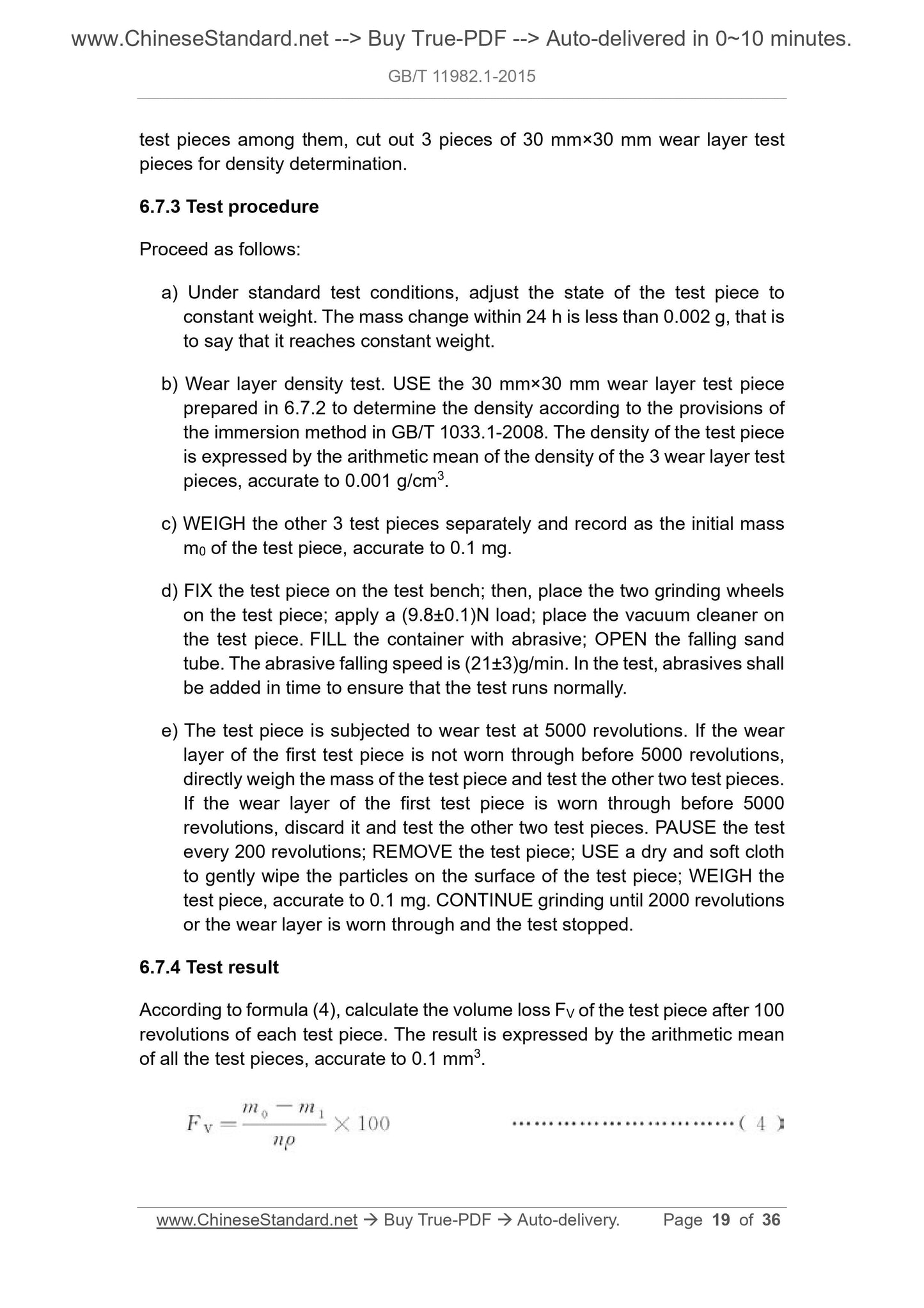
6.4.4 Test result
The surface mass is calculated according to formula (1). The deviation between
the arithmetic mean of the surface masses of the 5 test pieces and the explicit
surface mass value is calculated as a percentage and accurate to 1%.
Where:
A - Surface mass, in grams per square meter (g/m2);
m0 - The mass of test piece, in grams (g);
l - The length of test piece, in millimeters (mm);
b - The width of test piece, in millimeters (mm).
6.5 Variation rate of heating sizes
6.5.1 Instrument
6.5.1.1 Constant-temperature blast oven
Thermostat sensitivity is ±1 °C.
6.5.1.2 Vernier caliper
The division value is 0.02 mm.
6.5.2 Sampling
Before taking the test piece, the floor covering shall be laid as flat as possible.
TAKE 3 square test pieces with a size of 240 mm×240 mm from the floor
covering. Any side of the test piece shall be at least 100 mm from the edge of
the floor covering. Each side of each test piece shall be parallel or perpendicular
to the length or width direction of the product.
6.5.3 Test procedure
MARK the longitudinal and transverse directions on the test piece. As shown in
Figure 1, along the longitudinal and transverse distances of the test piece, at
20 mm from the edge of the test piece, draw two parallel lines with a distance
of 200 mm and mark 4 intersections. USE a Vernier caliper to measure the
distance L0 between each pair of marked lines in the longitudinal and transverse
directions, accurate to 0.02 mm. Then put the wear layer of the test piece
upward and lay it flat on a smooth glass plate or stainless steel plate sprinkled
with talcum powder. The distance between the test pieces shall be more than
50 mm; they shall be placed together in a constant-temperature blast oven with
a temperature of (80±2)°C. The distance between the flat plate and the inner
wall of the oven shall not be less than 50 mm. The vertical distance between
the flat plates and between the flat plate and the oven shall not be less than
100 mm. TAKE out after holding for 6 h; LEAVE them for 24 h under standard
test conditions. A 180 mm×180 mm×13 mm steel flat plate is pressed on the
test pieces. Then, measure the distance L between each pair of marked lines
of each test piece, accurate to 0.02 mm.
6.6.1.1 Constant-temperature blast oven
The...
Get QUOTATION in 1-minute: Click GB/T 11982.1-2015
Historical versions: GB/T 11982.1-2015
Preview True-PDF (Reload/Scroll if blank)
GB/T 11982.1-2015: Polyvinyl chloride floor coverings -- Part 1: Heterogeneous polyvinyl chloride floor coverings
GB/T 11982.1-2015
NATIONAL STANDARD OF THE
PEOPLE’S REPUBLIC OF CHINA
ICS 83.140
Q 22
Replacing GB/T 11982.1-2005
Polyvinyl chloride floor coverings - Part 1:
Heterogeneous polyvinyl chloride floor coverings
聚氯乙烯卷材地板
ISSUED ON: SEPTEMBER 11, 2015
IMPLEMENTED ON: AUGUST 01, 2016
Issued by: General Administration of Quality Supervision, Inspection and
Quarantine of the PRC;
Standardization Administration of the PRC.
Table of Contents
Foreword ... 3
1 Scope ... 5
2 Normative references ... 5
3 Terms and definitions ... 5
4 Classification, grade, and designation ... 6
5 Requirements ... 7
6 Test methods ... 10
7 Inspection rules ... 25
8 Marking, transportation, and storage ... 26
Appendix A (Normative) Classification table of use grades ... 28
Appendix B (Normative) Chair caster test method ... 30
Appendix C (Normative) Pollution resistance test method ... 34
Polyvinyl chloride floor coverings - Part 1:
Heterogeneous polyvinyl chloride floor coverings
1 Scope
This Part of GB/T 11982 specifies the terms and definitions, classification, grade
and designation, requirements, test methods, inspection rules, marking,
transportation, and storage of heterogeneous polyvinyl chloride floor coverings
(hereinafter referred to as floor coverings).
This Part applies to floor coverings with polyvinyl chloride resin as the main raw
material laid on the floor of the building.
2 Normative references
The following documents are indispensable for the application of this document.
For the dated references, only the editions with the dates indicated are
applicable to this document. For the undated references, the latest edition
(including all the amendments) are applicable to this document.
GB/T 1033.1-2008 Plastics - Methods for determining the density of non-
cellular plastics - Part 1: Immersion method, liquid pycnometer method and
titration method
GB/T 4100-2006 Ceramic tiles
GB/T 8427-2008 Textiles - Tests for color fastness - Color fastness to artificial
light: Xenon arc fading lamp test
GB 8624 Classification for burning behavior of building materials and
products
GB 18586 Indoor decorating and refurbishing materials - Limit of harmful
substances of polyvinyl chloride floor coverings
3 Terms and definitions
The following terms and definitions apply to this document.
3.1 Heterogeneous polyvinyl chloride floor coverings
5.3.4.2 Pollution resistance
REPORT test results.
5.3.4.3 Welding strength
USE grade 32 and above floor covering to conduct welding strength test as
agreed by the supplier and the purchaser. The average welding strength is ≥240
N/50 mm; the minimum is ≥180 N/50 mm.
5.3.4.4 Skid resistance
REPORT test results.
6 Test methods
6.1 Standard test conditions
The test piece, before the test, shall be left for at least 24 h under standard
conditions of temperature (23±2)°C and relative humidity (50±5)%. The test
shall be performed under these conditions.
6.2 Appearance
Under the scattered sunlight or fluorescent lamp, at 1 m from the test piece,
obliquely visually check the appearance. RECORD whether there are various
defects listed in Table 2.
6.3 Dimensional tolerances
6.3.1 Length
PUT the wear layer of the entire floor covering under test upwards. Without
tensile stress, lay it on a hard plane; USE a steel tape with a division value of 1
mm to measure the length at two positions parallel to the longitudinal direction
at about 200 mm from both sides. TAKE the arithmetic mean of the two length
measurement results to indicate the length of the floor covering, accurate to 10
mm.
6.3.2 Width
According to the method of 6.3.1, use a steel tape with a division value of 1 mm
to measure the width at the middle and both ends perpendicular to the
longitudinal direction. TAKE the smallest width to indicate the width of the floor
covering, accurate to 1 mm.
PLACE the test piece with the section facing up on a microscope test bench;
READ the thickness of the wear layer. If there are concave and convex patterns,
measure the thickness of the protruding part. 3 measurements are performed
on each test piece. RECORD the single thickness measured value of wear layer,
accurate to 0.01 mm.
6.3.3.2.4 Test result
Calculate the deviation of the arithmetic mean of all wear layer thickness
measurements from the stated wear layer thickness value, accurate to 1%; and
the deviation of a single wear layer thickness measurement from the arithmetic
mean of all wear layer thickness measurements, accurate to 0.01 mm.
6.4 Surface mass deviation
6.4.1 Instrument
6.4.1.1 Vernier caliper
The division value is not greater than 0.1 mm.
6.4.1.2 Balance
The sensitivity is not more than 0.01 g.
6.4.2 Sampling
TAKE 5 square test pieces with a size of 100 mm×100 mm from the floor
covering. Any side of the test piece shall be at least 100 mm from the edge of
the floor covering.
6.4.3 Test procedure
MEASURE the side length of the middle of each test piece, accurate to 0.1 mm.
WEIGH and record the mass m0 of each test piece, accurate to 0.01 g.
6.4.4 Test result
The surface mass is calculated according to formula (1). The deviation between
the arithmetic mean of the surface masses of the 5 test pieces and the explicit
surface mass value is calculated as a percentage and accurate to 1%.
Where:
A - Surface mass, in grams per square meter (g/m2);
m0 - The mass of test piece, in grams (g);
l - The length of test piece, in millimeters (mm);
b - The width of test piece, in millimeters (mm).
6.5 Variation rate of heating sizes
6.5.1 Instrument
6.5.1.1 Constant-temperature blast oven
Thermostat sensitivity is ±1 °C.
6.5.1.2 Vernier caliper
The division value is 0.02 mm.
6.5.2 Sampling
Before taking the test piece, the floor covering shall be laid as flat as possible.
TAKE 3 square test pieces with a size of 240 mm×240 mm from the floor
covering. Any side of the test piece shall be at least 100 mm from the edge of
the floor covering. Each side of each test piece shall be parallel or perpendicular
to the length or width direction of the product.
6.5.3 Test procedure
MARK the longitudinal and transverse directions on the test piece. As shown in
Figure 1, along the longitudinal and transverse distances of the test piece, at
20 mm from the edge of the test piece, draw two parallel lines with a distance
of 200 mm and mark 4 intersections. USE a Vernier caliper to measure the
distance L0 between each pair of marked lines in the longitudinal and transverse
directions, accurate to 0.02 mm. Then put the wear layer of the test piece
upward and lay it flat on a smooth glass plate or stainless steel plate sprinkled
with talcum powder. The distance between the test pieces shall be more than
50 mm; they shall be placed together in a constant-temperature blast oven with
a temperature of (80±2)°C. The distance between the flat plate and the inner
wall of the oven shall not be less than 50 mm. The vertical distance between
the flat plates and between the flat plate and the oven shall not be less than
100 mm. TAKE out after holding for 6 h; LEAVE them for 24 h under standard
test conditions. A 180 mm×180 mm×13 mm steel flat plate is pressed on the
test pieces. Then, measure the distance L between each pair of marked lines
of each test piece, accurate to 0.02 mm.
6.6.1.1 Constant-temperature blast oven
The...
Share