

PayPal, credit cards. Download editable-PDF & invoice in 1 second!
GB/T 36282-2018 English PDF (GBT36282-2018)
GB/T 36282-2018 English PDF (GBT36282-2018)
Precio habitual
$145.00 USD
Precio habitual
Precio de oferta
$145.00 USD
Precio unitario
/
por
Los gastos de envío se calculan en la pantalla de pago.
No se pudo cargar la disponibilidad de retiro
Delivery: 3 seconds. Download true-PDF + Invoice.
Get QUOTATION in 1-minute: Click GB/T 36282-2018
Historical versions: GB/T 36282-2018
Preview True-PDF (Reload/Scroll if blank)
GB/T 36282-2018: Electromagnetic compatibility requirements and test methods of drive motor system for electric vehicles
GB/T 36282-2018
GB
NATIONAL STANDARD OF THE
PEOPLE’S REPUBLIC OF CHINA
ICS 43.040
T 35
Electromagnetic compatibility requirements and test
methods of drive motor system for electric vehicles
ISSUED ON. JUNE 07, 2018
IMPLEMENTED ON. JANUARY 01, 2019
Issued by. State market regulatory administration;
Standardization Administration of PRC.
Table of Contents
Foreword ... 3
1 Scope ... 4
2 Normative references ... 4
3 Terms and definitions ... 5
4 Requirements ... 6
4.1 Electromagnetic radiation emission ... 6
4.2 Immunity ... 7
5 Test methods ... 8
5.1 Electromagnetic radiation emission test ... 8
5.2 Immunity test ... 12
6 Test report ... 19
Appendix A (Normative) Functional status classification ... 20
Appendix B (Normative) Immunity test level ... 21
Appendix C (Informative) Test report requirements ... 23
References ... 24
Electromagnetic compatibility requirements and test
methods of drive motor system for electric vehicles
1 Scope
This standard specifies the electromagnetic compatibility requirements and test
methods of drive motor system for electric vehicles.
This standard applies to the drive motor systems of pure electric vehicles,
hybrid electric vehicles and fuel cell electric vehicle.
In this standard, it considers the HV (high voltage) power system component
as a typical full shielding system.
Note. Electric vehicle power systems are usually divided into two types. the first
type is common LV (low voltage) system, its typical structural features are
unshielded; and the second type is HV system, its typical structural features are
shielded.
2 Normative references
The following documents are essential to the application of this document. For
the dated documents, only the versions with the dates indicated are applicable
to this document; for the undated documents, only the latest version (including
all the amendments) are applicable to this standard.
GB/T 18384.3-2015 Electrically propelled road vehicles - Safety
specifications - Part 3. Protection of persons against electric shock
GB/T 18655-2010 Vehicles boats and internal combustion engines - Radio
disturbance characteristics - Limits and methods of measurement for the
protection of on-board receivers
GB/T 19951 Road vehicles - Test methods for electrical disturbances from
electrostatic discharge
GB/T 21437.2-2008 Road vehicles - Electrical disturbances from conduction
and coupling - Part 2. Electrical transient conduction along supply lines only
GB/T 29259 Road vehicle - Electromagnetic compatibility terminology
GB/T 33014.1 Road vehicles - Component test methods for
can be specified in the test report.
If the EUT contains multiple units, the connection line between the units shall
use the connection harness used in the original vehicle; if this is not possible,
the length of the connection line between the electronic control unit and the
artificial power supply network (AN) shall be in accordance with this standard.
The wiring harness shall be terminated as required and with actual load and
excitation.
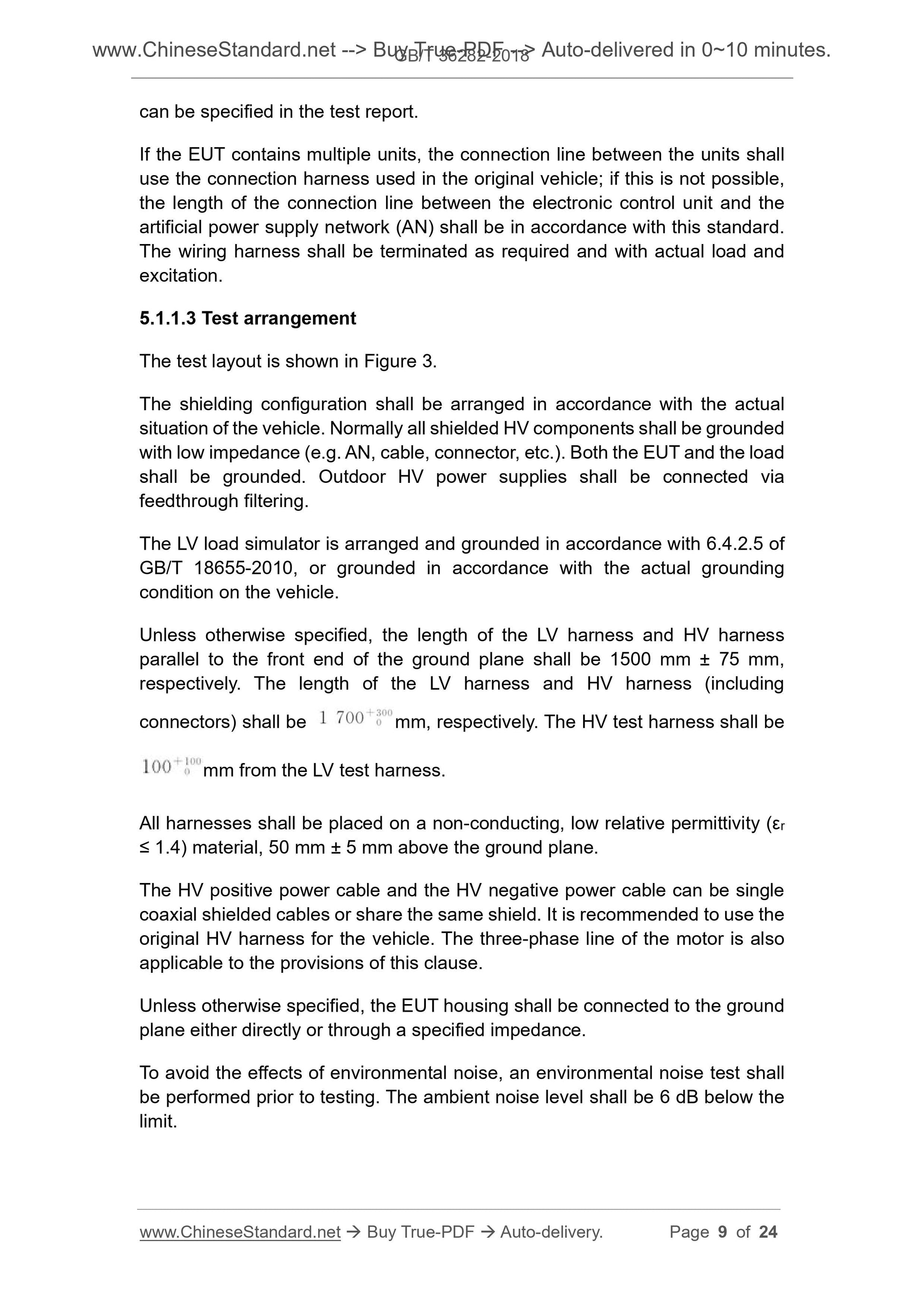
5.1.1.3 Test arrangement
The test layout is shown in Figure 3.
The shielding configuration shall be arranged in accordance with the actual
situation of the vehicle. Normally all shielded HV components shall be grounded
with low impedance (e.g. AN, cable, connector, etc.). Both the EUT and the load
shall be grounded. Outdoor HV power supplies shall be connected via
feedthrough filtering.
The LV load simulator is arranged and grounded in accordance with 6.4.2.5 of
GB/T 18655-2010, or grounded in accordance with the actual grounding
condition on the vehicle.
Unless otherwise specified, the length of the LV harness and HV harness
parallel to the front end of the ground plane shall be 1500 mm ± 75 mm,
respectively. The length of the LV harness and HV harness (including
connectors) shall be mm, respectively. The HV test harness shall be
mm from the LV test harness.
All harnesses shall be placed on a non-conducting, low relative permittivity (εr
≤ 1.4) material, 50 mm ± 5 mm above the ground plane.
The HV positive power cable and the HV negative power cable can be single
coaxial shielded cables or share the same shield. It is recommended to use the
original HV harness for the vehicle. The three-phase line of the motor is also
applicable to the provisions of this clause.
Unless otherwise specified, the EUT housing shall be connected to the ground
plane either directly or through a specified impedance.
To avoid the effects of environmental noise, an environmental noise test shall
be performed prior to testing. The ambient noise level shall be 6 dB below the
limit.
Measurements shall be made in a semi-anechoic chamber with a frequency
range of 30 MHz ~ 1000 MHz.
Measurements shall be made under vertical polarization and horizontal
polarization of the antenna, respectively.
Measurements can be made using a spectrum analyzer or a scanning receiver.
The measurement parameters shall be set in accordance with the provisions of
GB/T 18655-2010.
To speed up the test, a peak detector can be used for scanning, but when the
peak measurement exceeds the limit requirements in 4.1.1, a quasi-peak
detector shall be used for the final test.
5.1.2 Narrowband electromagnetic radiation emission test
5.1.2.1 Test method
The method is for testing narrowband electromagnetic radiation emissions
produced by an EUT, such as a microprocessor-based system. If there is no
other explanation, in the frequency range of 30 MHz ~ 1000 MHz, the test shall
be carried out in accordance with the method specified in GB/T 18655-2010.
5.1.2.2 Test status
The HV and LV are powered normally, the EUT drive module is in standby mode
with no output power.
5.1.2.3 Test arrangement
Same as the test layout requirements of 5.1.1.3, as shown in Figure 3.
5.1.2.4 Test requirements
Measurements shall be made in a semi-anechoic chamber with a frequency
range of 30 MHz ~ 1000 MHz.
Measurements shall be made under vertical polarization and horizontal
polarization of the antenna, respectively.
Measurements can be made using a spectrum analyzer or a scanning receiver.
The measurement parameters shall be set in accordance with the provisions of
GB/T 18655-2010.
5.2 Immunity test
5.2.1 Electromagnetic radiation immunity
The EUT shall be in normal operation with a speed of 50% of the rated speed,
a torque of 50% of the rated torque, and a mechanical output load of 25% of
the continuous power.
When the speed or torque does not reach the EUT test status, the torque or
speed can be adjusted to achieve 25% of the continuous power, which shall be
noted in the test report.
Note. When the power requirements are not met, the working status of the EUT
can be specified in the test report.
5.2.1.3 Test arrangement
The big current injection (BCI) test layout is shown in Figure 4; the anechoic
chamber (ALSE) test layout is shown in Figure 5.
Figure 5 only shows an example of the test arrangement of the horn antenna
when the EUT is used above 1 GHz. The 200 MHz ~ 1 GHz frequency range
can be tested using a double cone antenna.
The shielding configuration shall be configured in accordance with the vehicle's
series. Normally all shielded HV components shall be grounded with low
impedance (e.g. AN, cable, connector, etc.). The EUT and load shall be
grounded. Outdoor HV power suppli...
Get QUOTATION in 1-minute: Click GB/T 36282-2018
Historical versions: GB/T 36282-2018
Preview True-PDF (Reload/Scroll if blank)
GB/T 36282-2018: Electromagnetic compatibility requirements and test methods of drive motor system for electric vehicles
GB/T 36282-2018
GB
NATIONAL STANDARD OF THE
PEOPLE’S REPUBLIC OF CHINA
ICS 43.040
T 35
Electromagnetic compatibility requirements and test
methods of drive motor system for electric vehicles
ISSUED ON. JUNE 07, 2018
IMPLEMENTED ON. JANUARY 01, 2019
Issued by. State market regulatory administration;
Standardization Administration of PRC.
Table of Contents
Foreword ... 3
1 Scope ... 4
2 Normative references ... 4
3 Terms and definitions ... 5
4 Requirements ... 6
4.1 Electromagnetic radiation emission ... 6
4.2 Immunity ... 7
5 Test methods ... 8
5.1 Electromagnetic radiation emission test ... 8
5.2 Immunity test ... 12
6 Test report ... 19
Appendix A (Normative) Functional status classification ... 20
Appendix B (Normative) Immunity test level ... 21
Appendix C (Informative) Test report requirements ... 23
References ... 24
Electromagnetic compatibility requirements and test
methods of drive motor system for electric vehicles
1 Scope
This standard specifies the electromagnetic compatibility requirements and test
methods of drive motor system for electric vehicles.
This standard applies to the drive motor systems of pure electric vehicles,
hybrid electric vehicles and fuel cell electric vehicle.
In this standard, it considers the HV (high voltage) power system component
as a typical full shielding system.
Note. Electric vehicle power systems are usually divided into two types. the first
type is common LV (low voltage) system, its typical structural features are
unshielded; and the second type is HV system, its typical structural features are
shielded.
2 Normative references
The following documents are essential to the application of this document. For
the dated documents, only the versions with the dates indicated are applicable
to this document; for the undated documents, only the latest version (including
all the amendments) are applicable to this standard.
GB/T 18384.3-2015 Electrically propelled road vehicles - Safety
specifications - Part 3. Protection of persons against electric shock
GB/T 18655-2010 Vehicles boats and internal combustion engines - Radio
disturbance characteristics - Limits and methods of measurement for the
protection of on-board receivers
GB/T 19951 Road vehicles - Test methods for electrical disturbances from
electrostatic discharge
GB/T 21437.2-2008 Road vehicles - Electrical disturbances from conduction
and coupling - Part 2. Electrical transient conduction along supply lines only
GB/T 29259 Road vehicle - Electromagnetic compatibility terminology
GB/T 33014.1 Road vehicles - Component test methods for
can be specified in the test report.
If the EUT contains multiple units, the connection line between the units shall
use the connection harness used in the original vehicle; if this is not possible,
the length of the connection line between the electronic control unit and the
artificial power supply network (AN) shall be in accordance with this standard.
The wiring harness shall be terminated as required and with actual load and
excitation.
5.1.1.3 Test arrangement
The test layout is shown in Figure 3.
The shielding configuration shall be arranged in accordance with the actual
situation of the vehicle. Normally all shielded HV components shall be grounded
with low impedance (e.g. AN, cable, connector, etc.). Both the EUT and the load
shall be grounded. Outdoor HV power supplies shall be connected via
feedthrough filtering.
The LV load simulator is arranged and grounded in accordance with 6.4.2.5 of
GB/T 18655-2010, or grounded in accordance with the actual grounding
condition on the vehicle.
Unless otherwise specified, the length of the LV harness and HV harness
parallel to the front end of the ground plane shall be 1500 mm ± 75 mm,
respectively. The length of the LV harness and HV harness (including
connectors) shall be mm, respectively. The HV test harness shall be
mm from the LV test harness.
All harnesses shall be placed on a non-conducting, low relative permittivity (εr
≤ 1.4) material, 50 mm ± 5 mm above the ground plane.
The HV positive power cable and the HV negative power cable can be single
coaxial shielded cables or share the same shield. It is recommended to use the
original HV harness for the vehicle. The three-phase line of the motor is also
applicable to the provisions of this clause.
Unless otherwise specified, the EUT housing shall be connected to the ground
plane either directly or through a specified impedance.
To avoid the effects of environmental noise, an environmental noise test shall
be performed prior to testing. The ambient noise level shall be 6 dB below the
limit.
Measurements shall be made in a semi-anechoic chamber with a frequency
range of 30 MHz ~ 1000 MHz.
Measurements shall be made under vertical polarization and horizontal
polarization of the antenna, respectively.
Measurements can be made using a spectrum analyzer or a scanning receiver.
The measurement parameters shall be set in accordance with the provisions of
GB/T 18655-2010.
To speed up the test, a peak detector can be used for scanning, but when the
peak measurement exceeds the limit requirements in 4.1.1, a quasi-peak
detector shall be used for the final test.
5.1.2 Narrowband electromagnetic radiation emission test
5.1.2.1 Test method
The method is for testing narrowband electromagnetic radiation emissions
produced by an EUT, such as a microprocessor-based system. If there is no
other explanation, in the frequency range of 30 MHz ~ 1000 MHz, the test shall
be carried out in accordance with the method specified in GB/T 18655-2010.
5.1.2.2 Test status
The HV and LV are powered normally, the EUT drive module is in standby mode
with no output power.
5.1.2.3 Test arrangement
Same as the test layout requirements of 5.1.1.3, as shown in Figure 3.
5.1.2.4 Test requirements
Measurements shall be made in a semi-anechoic chamber with a frequency
range of 30 MHz ~ 1000 MHz.
Measurements shall be made under vertical polarization and horizontal
polarization of the antenna, respectively.
Measurements can be made using a spectrum analyzer or a scanning receiver.
The measurement parameters shall be set in accordance with the provisions of
GB/T 18655-2010.
5.2 Immunity test
5.2.1 Electromagnetic radiation immunity
The EUT shall be in normal operation with a speed of 50% of the rated speed,
a torque of 50% of the rated torque, and a mechanical output load of 25% of
the continuous power.
When the speed or torque does not reach the EUT test status, the torque or
speed can be adjusted to achieve 25% of the continuous power, which shall be
noted in the test report.
Note. When the power requirements are not met, the working status of the EUT
can be specified in the test report.
5.2.1.3 Test arrangement
The big current injection (BCI) test layout is shown in Figure 4; the anechoic
chamber (ALSE) test layout is shown in Figure 5.
Figure 5 only shows an example of the test arrangement of the horn antenna
when the EUT is used above 1 GHz. The 200 MHz ~ 1 GHz frequency range
can be tested using a double cone antenna.
The shielding configuration shall be configured in accordance with the vehicle's
series. Normally all shielded HV components shall be grounded with low
impedance (e.g. AN, cable, connector, etc.). The EUT and load shall be
grounded. Outdoor HV power suppli...
Share