PayPal, credit cards. Download editable-PDF & invoice in 1 second!
JJG 762-2007 English PDF (JJG762-2007)
JJG 762-2007 English PDF (JJG762-2007)
Precio habitual
$210.00 USD
Precio habitual
Precio de oferta
$210.00 USD
Precio unitario
/
por
Los gastos de envío se calculan en la pantalla de pago.
No se pudo cargar la disponibilidad de retiro
Delivery: 3 seconds. Download true-PDF + Invoice.
Get QUOTATION in 1-minute: Click JJG 762-2007
Historical versions: JJG 762-2007
Preview True-PDF (Reload/Scroll if blank)
JJG 762-2007: Verification Regulation for Extensometer
JJG 762-2007
NATIONAL METROLOGICAL VERIFICATION REGULATION
OF THE PEOPLE’S REPUBLIC OF CHINA
Extensometer
引伸计
ISSUED ON: AUGUST 21, 2007
IMPLEMENTED ON: FEBRUARY 21, 2008
Issued by: General Administration of Quality Supervision, Inspection
and Quarantine of the People's Republic of China
Table of Contents
1 Scope ... 5
2 Citations ... 5
3 Overview ... 5
4 Measurement performance requirements ... 6
5 General technical requirements ... 7
5.1 Nameplate ... 7
5.2 Appearance and quality ... 7
5.3 Display and output ... 7
6 Control of measuring instruments ... 7
6.1 Verification conditions ... 7
6.2 Verification items and verification methods ... 8
6.3 Processing of verification results ... 11
6.4 Verification cycle ... 11
Appendix A Extensometer verification certificate inner page format ... 12
Appendix B Extensometer verification record format ... 13
Appendix C Example of extensometer error band ... 14
Appendix D Extensometer verification example ... 15
Verification Regulation for Extensometer
1 Scope
This Regulation is applicable to the first verification, subsequent verification and
in-service verification of extensometers.
2 Citations
The following documents are cited in this Regulation:
GB/T 228-2002, Metallic materials - Tensile testing at ambient temperature
GB/T 1040.1-2006, Plastics - Determination of tensile properties - Part 1:
General principles
GB/T 7314-2005, Metallic materials - Compression testing at ambient
temperature
GB/T 12160-2002/ ISO 953:1999, Calibration of extensometers used in
uniaxial testing
JJF 1096-2002, Calibration Specification for Calibrator of Extensometers
ASTM E83-02, Standard Practice for Verification and Classification of
Extensometer System
During the use of this Regulation, please pay attention to the currently valid
version of the above-cited documents.
3 Overview
3.1 Extensometer is a device for the measurement of sample line deformation
when the test machine applies axial force to the sample, including the
measurement, indicating or recording systems. According to the structural
characteristics, it is divided into two types: electronic and mechanical.
Note: Electronic extensometers, such as resistance-strain and inductive extensometers, need
to be equipped with corresponding amplifiers, computers or indicating devices to automatically
record or display the measured displacement indications. Therefore, the calibration of electronic
extensometer must include the entire measurement system. Mechanical extensometers, such
as dial gauge, lever type, and optical extensometers, directly indicate the displacement
indications by a pointer or a cursor.
5 General technical requirements
5.1 Nameplate
The nameplate of the extensometer and its supporting instruments shall be
marked with the instrument name, model, manufacturer name, product number
and date of manufacture.
5.2 Appearance and quality
The extensometer and its accessories shall not have obvious mechanical
damage; the blade, shaft tip and other structures that set the gauge length shall
not have obvious wear; the indicating device and measuring mechanism shall
not have defects that affect the measurement results.
5.3 Display and output
The display of the electronic extensometer shall be clear, complete and stable;
the printed results or drawn curves shall be consistent with the indicated values.
6 Control of measuring instruments
Control of measuring instruments includes: first verification, subsequent
verification and in-service verification.
6.1 Verification conditions
6.1.1 Environmental conditions
The verification temperature range shall be 23°C ± 5°C; the temperature during
the verification shall be stable; the temperature change shall not exceed 2°C;
the air convection that affects the verification result of the extensometer is not
allowed during the verification.
For the test extensometer in the temperature range of 10°C ~ 35°C, if necessary,
the test can also be carried out at or near the test temperature.
The extensometer and the calibrator shall be placed at the same room
temperature for not less than 30 minutes; the verification shall be performed
after the temperature is equilibrated.
6.1.2 Standard equipment for verification
6.1.2.1 The extensometer calibrator shall meet the requirements of JJF 1096-
2002; its allowable error shall conform to the requirements of Table 2.
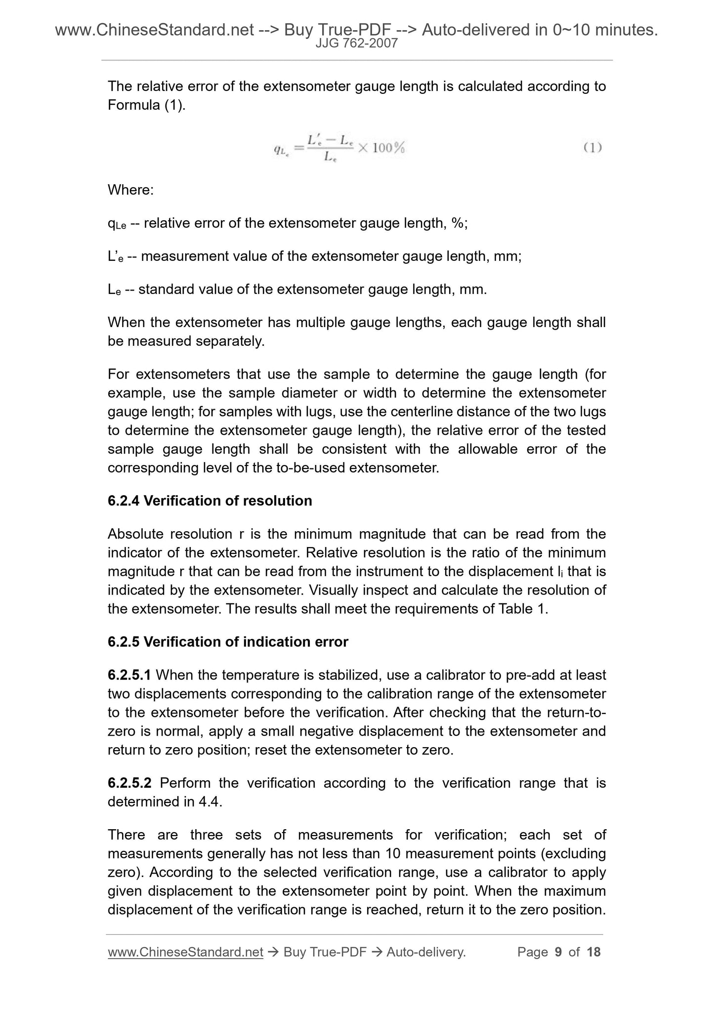
The relative error of the extensometer gauge length is calculated according to
Formula (1).
Where:
qLe -- relative error of the extensometer gauge length, %;
L’e -- measurement value of the extensometer gauge length, mm;
Le -- standard value of the extensometer gauge length, mm.
When the extensometer has multiple gauge lengths, each gauge length shall
be measured separately.
For extensometers that use the sample to determine the gauge length (for
example, use the sample diameter or width to determine the extensometer
gauge length; for samples with lugs, use the centerline distance of the two lugs
to determine the extensometer gauge length), the relative error of the tested
sample gauge length shall be consistent with the allowable error of the
corresponding level of the to-be-used extensometer.
6.2.4 Verification of resolution
Absolute resolution r is the minimum magnitude that can be read from the
indicator of the extensometer. Relative resolution is the ratio of the minimum
magnitude r that can be read from the instrument to the displacement li that is
indicated by the extensometer. Visually inspect and calculate the resolution of
the extensometer. The results shall meet the requirements of Table 1.
6.2.5 Verification of indication error
6.2.5.1 When the temperature is stabilized, use a calibrator to pre-add at least
two displacements corresponding to the calibration range of the extensometer
to the extensometer before the verification. After checking that the return-to-
zero is normal, apply a small negative displacement to the extensometer and
return to zero position; reset the extensometer to zero.
6.2.5.2 Perform the verification according to the verification range that is
determined in 4.4.
There are three sets of measurements for verification; each set of
measurements generally has not less than 10 measurement points (excluding
zero). According to the selected verification range, use a calibrator to apply
given displacement to the extensometer point by point. When the maximum
displacement of the verification range is reached, return it to the zero position.
u -- relative forward-return error of indicating-value of the extensometer, %;
l’i – return-stroke displacement indicating-value that is indicated by the
extensometer at the same detection point, mm;
li -- forward-stroke displacement indicating-value that is indicated by the
extensometer at the same detection point, mm;
6.3 Processing of verification results
6.3.1 Assess the level of the extensometer according to the verification results
of this Regulation, and issue a verification certificate. The format of the inside
page of the certificate is shown in Appendix A.
The extensometer that fails to pass the verification is issued with a notice of the
verification result. The unqualified items shall be indicated. For the format of the
inner page, see Appendix A.
For the extensometer that is verified for multiple verification ranges and multiple
gauge lengths, the...
Get QUOTATION in 1-minute: Click JJG 762-2007
Historical versions: JJG 762-2007
Preview True-PDF (Reload/Scroll if blank)
JJG 762-2007: Verification Regulation for Extensometer
JJG 762-2007
NATIONAL METROLOGICAL VERIFICATION REGULATION
OF THE PEOPLE’S REPUBLIC OF CHINA
Extensometer
引伸计
ISSUED ON: AUGUST 21, 2007
IMPLEMENTED ON: FEBRUARY 21, 2008
Issued by: General Administration of Quality Supervision, Inspection
and Quarantine of the People's Republic of China
Table of Contents
1 Scope ... 5
2 Citations ... 5
3 Overview ... 5
4 Measurement performance requirements ... 6
5 General technical requirements ... 7
5.1 Nameplate ... 7
5.2 Appearance and quality ... 7
5.3 Display and output ... 7
6 Control of measuring instruments ... 7
6.1 Verification conditions ... 7
6.2 Verification items and verification methods ... 8
6.3 Processing of verification results ... 11
6.4 Verification cycle ... 11
Appendix A Extensometer verification certificate inner page format ... 12
Appendix B Extensometer verification record format ... 13
Appendix C Example of extensometer error band ... 14
Appendix D Extensometer verification example ... 15
Verification Regulation for Extensometer
1 Scope
This Regulation is applicable to the first verification, subsequent verification and
in-service verification of extensometers.
2 Citations
The following documents are cited in this Regulation:
GB/T 228-2002, Metallic materials - Tensile testing at ambient temperature
GB/T 1040.1-2006, Plastics - Determination of tensile properties - Part 1:
General principles
GB/T 7314-2005, Metallic materials - Compression testing at ambient
temperature
GB/T 12160-2002/ ISO 953:1999, Calibration of extensometers used in
uniaxial testing
JJF 1096-2002, Calibration Specification for Calibrator of Extensometers
ASTM E83-02, Standard Practice for Verification and Classification of
Extensometer System
During the use of this Regulation, please pay attention to the currently valid
version of the above-cited documents.
3 Overview
3.1 Extensometer is a device for the measurement of sample line deformation
when the test machine applies axial force to the sample, including the
measurement, indicating or recording systems. According to the structural
characteristics, it is divided into two types: electronic and mechanical.
Note: Electronic extensometers, such as resistance-strain and inductive extensometers, need
to be equipped with corresponding amplifiers, computers or indicating devices to automatically
record or display the measured displacement indications. Therefore, the calibration of electronic
extensometer must include the entire measurement system. Mechanical extensometers, such
as dial gauge, lever type, and optical extensometers, directly indicate the displacement
indications by a pointer or a cursor.
5 General technical requirements
5.1 Nameplate
The nameplate of the extensometer and its supporting instruments shall be
marked with the instrument name, model, manufacturer name, product number
and date of manufacture.
5.2 Appearance and quality
The extensometer and its accessories shall not have obvious mechanical
damage; the blade, shaft tip and other structures that set the gauge length shall
not have obvious wear; the indicating device and measuring mechanism shall
not have defects that affect the measurement results.
5.3 Display and output
The display of the electronic extensometer shall be clear, complete and stable;
the printed results or drawn curves shall be consistent with the indicated values.
6 Control of measuring instruments
Control of measuring instruments includes: first verification, subsequent
verification and in-service verification.
6.1 Verification conditions
6.1.1 Environmental conditions
The verification temperature range shall be 23°C ± 5°C; the temperature during
the verification shall be stable; the temperature change shall not exceed 2°C;
the air convection that affects the verification result of the extensometer is not
allowed during the verification.
For the test extensometer in the temperature range of 10°C ~ 35°C, if necessary,
the test can also be carried out at or near the test temperature.
The extensometer and the calibrator shall be placed at the same room
temperature for not less than 30 minutes; the verification shall be performed
after the temperature is equilibrated.
6.1.2 Standard equipment for verification
6.1.2.1 The extensometer calibrator shall meet the requirements of JJF 1096-
2002; its allowable error shall conform to the requirements of Table 2.
The relative error of the extensometer gauge length is calculated according to
Formula (1).
Where:
qLe -- relative error of the extensometer gauge length, %;
L’e -- measurement value of the extensometer gauge length, mm;
Le -- standard value of the extensometer gauge length, mm.
When the extensometer has multiple gauge lengths, each gauge length shall
be measured separately.
For extensometers that use the sample to determine the gauge length (for
example, use the sample diameter or width to determine the extensometer
gauge length; for samples with lugs, use the centerline distance of the two lugs
to determine the extensometer gauge length), the relative error of the tested
sample gauge length shall be consistent with the allowable error of the
corresponding level of the to-be-used extensometer.
6.2.4 Verification of resolution
Absolute resolution r is the minimum magnitude that can be read from the
indicator of the extensometer. Relative resolution is the ratio of the minimum
magnitude r that can be read from the instrument to the displacement li that is
indicated by the extensometer. Visually inspect and calculate the resolution of
the extensometer. The results shall meet the requirements of Table 1.
6.2.5 Verification of indication error
6.2.5.1 When the temperature is stabilized, use a calibrator to pre-add at least
two displacements corresponding to the calibration range of the extensometer
to the extensometer before the verification. After checking that the return-to-
zero is normal, apply a small negative displacement to the extensometer and
return to zero position; reset the extensometer to zero.
6.2.5.2 Perform the verification according to the verification range that is
determined in 4.4.
There are three sets of measurements for verification; each set of
measurements generally has not less than 10 measurement points (excluding
zero). According to the selected verification range, use a calibrator to apply
given displacement to the extensometer point by point. When the maximum
displacement of the verification range is reached, return it to the zero position.
u -- relative forward-return error of indicating-value of the extensometer, %;
l’i – return-stroke displacement indicating-value that is indicated by the
extensometer at the same detection point, mm;
li -- forward-stroke displacement indicating-value that is indicated by the
extensometer at the same detection point, mm;
6.3 Processing of verification results
6.3.1 Assess the level of the extensometer according to the verification results
of this Regulation, and issue a verification certificate. The format of the inside
page of the certificate is shown in Appendix A.
The extensometer that fails to pass the verification is issued with a notice of the
verification result. The unqualified items shall be indicated. For the format of the
inner page, see Appendix A.
For the extensometer that is verified for multiple verification ranges and multiple
gauge lengths, the...
Share