


PayPal, credit cards. Download editable-PDF & invoice in 1 second!
YY/T 1603-2018 English PDF (YYT1603-2018)
YY/T 1603-2018 English PDF (YYT1603-2018)
Precio habitual
$245.00 USD
Precio habitual
Precio de oferta
$245.00 USD
Precio unitario
/
por
Los gastos de envío se calculan en la pantalla de pago.
No se pudo cargar la disponibilidad de retiro
Delivery: 3 seconds. Download true-PDF + Invoice.
Get QUOTATION in 1-minute: Click YY/T 1603-2018
Historical versions: YY/T 1603-2018
Preview True-PDF (Reload/Scroll if blank)
YY/T 1603-2018: Medical endoscopes--Endoscope supply units--Video camera system
YY/T 1603-2018
YY
PHARMACEUTICAL INDUSTRY STANDARD
OF THE PEOPLE’S REPUBLIC OF CHINA
ICS 11.040.99
C 40
Medical Endoscopes - Endoscope Supply Units -
Video Camera System
ISSUED ON: JANUARY 19, 2018
IMPLEMENTED ON: JANUARY 01, 2019
Issued by: China Food and Drug Administration
Table of Contents
Foreword ... 3
1 Scope ... 4
2 Normative References ... 4
3 Terms and Definitions ... 4
4 requirements ... 6
5 Test Methods ... 7
Appendix A (Normative) Test Methods of Brightness Response Characteristic 9
Appendix B (Normative) Test Methods of Signal-to-Noise Ratio ... 14
Appendix C (Normative) Test Methods of Spatial Frequency Response ... 18
Appendix D (Normative) Test Methods of Static Image Latitude ... 24
Medical Endoscopes - Endoscope Supply Units -
Video Camera System
1 Scope
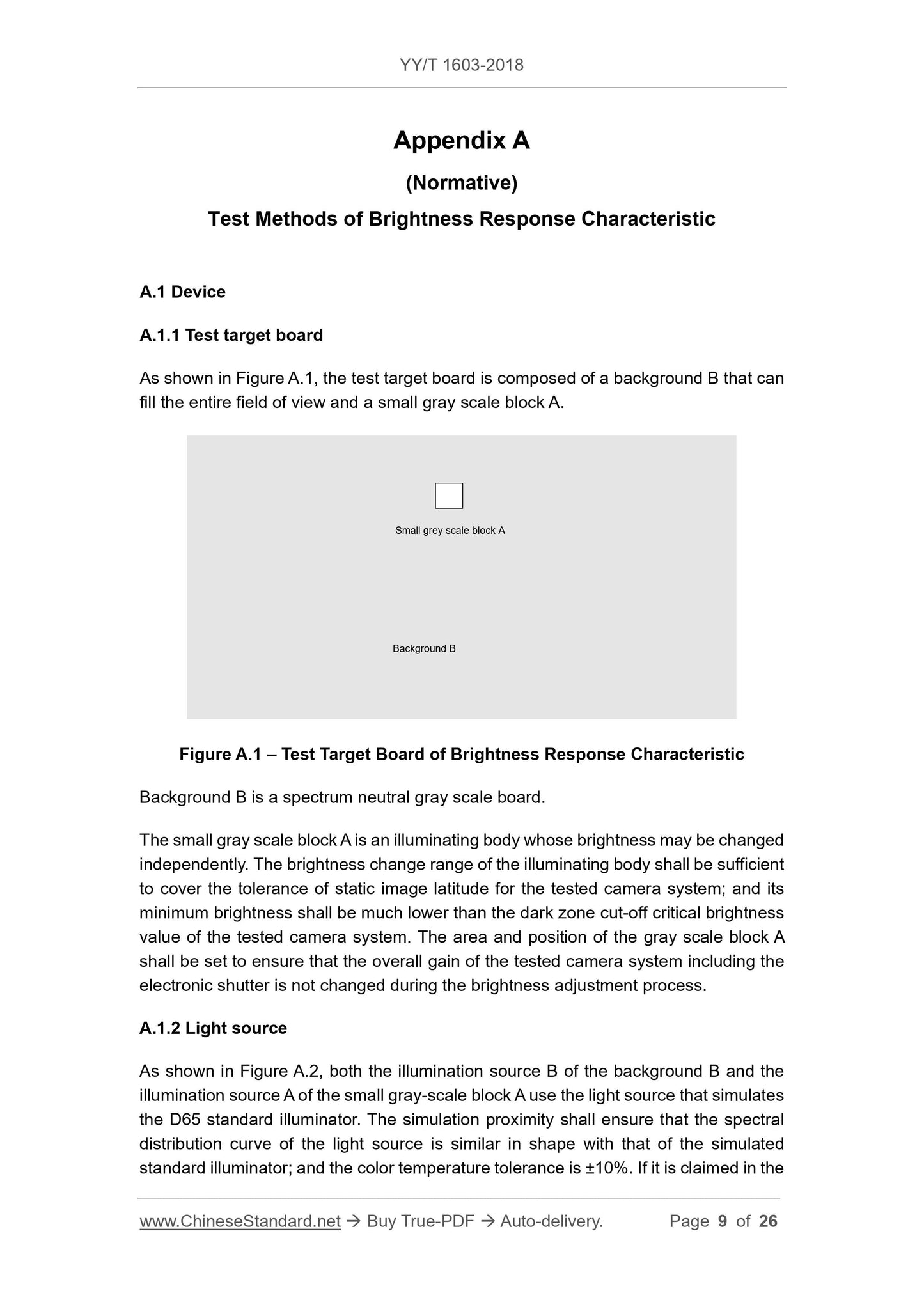
This Standard specifies the terms, definitions, requirements, and test methods for
medical endoscopic camera system.
This Standard is applicable to medical endoscopic camera system (hereinafter referred
to as camera system) that are used as endoscope supply units in endoscopy and
surgery.
This Standard is not applicable to the camera system with special spectral effects and
non-visible spectral imaging.
2 Normative References
The following documents are essential to the application of this document. For the
dated documents, only the versions with the dates indicated are applicable to this
document; for the undated documents, only the latest version (including all the
amendments) are applicable to this document.
GB 9706.19 Medical Electrical Equipment - Part 2: Particular Requirements for the
Safety of Endoscopic Equipment
3 Terms and Definitions
For the purpose of this document, the following terms and definitions apply.
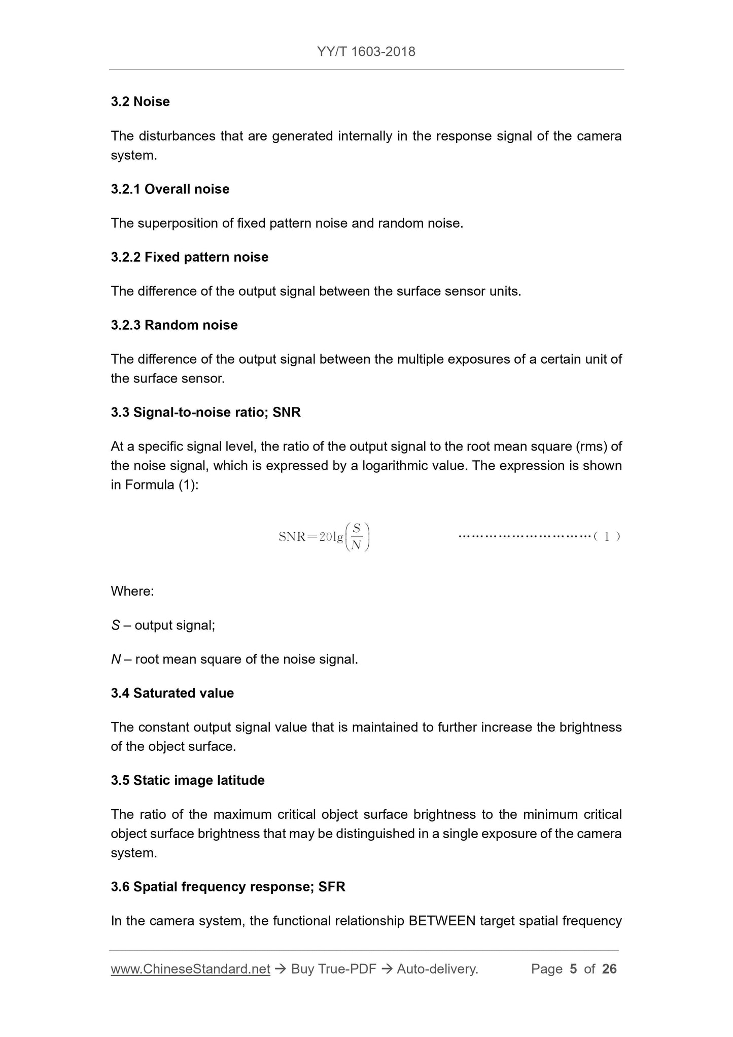
3.1 Conversion function
3.1.1 Opto-electronic conversion function; OECF
The ideal relationship between the object brightness and the corresponding output
signal of the camera system.
3.1.2 Electro-optical conversion function
The inverse function of OECF.
AND the ratio of the modulation degree of the output signal calculated by the OECF
inverse function to the modulation degree of the target object surface brightness.
3.7 Sine-based spatial frequency response; s-SFR
SFR when the target is a sine wave modulation diagram.
3.8 Modulation degree
The ratio BETWEEN the maximum signal value minus the minimum signal value AND
the maximum signal value plus the minimum signal value.
3.9 Spectral neutrality
The reflection or transmission characteristics that is maintained constant against a
certain wavelength of light.
4 requirements
4.1 Requirements for detachable lens
4.1.1 Modulation transfer function (MTF)
The manufacturer shall give the nominal value of the spatial frequency corresponding
to the MTF value of the detachable lens at 50% in the attached information, the
tolerance is -20%, and the upper limit is not counted.
4.1.2 Focal length
The manufacturer shall provide the focal length parameters of the detachable lens in
the attached information. For the lens with a fixed focal length, the tolerance for
nominal value of the focal length is ±20%. For the lens with variable magnification, the
tolerance for nominal value of the minimum focal length is +20%, and the lower limit is
not counted; the tolerance for nominal value of the maximum focal length is -20%, and
the upper limit is not counted.
4.2 Brightness response characteristics
The manufacturer shall provide the output brightness electro-optical conversion
function or data list of the adapted monitor expressed in relative value in the technical
data. The sampling points of the data list are no less than 10, and cover the entire
latitude area.
The output signal of the camera system shall maintain a good linearity between the
brightness calculated according to the electro-optical characteristics and the
brightness of each gray scale of the actual tested target board; and the linear fitting
5.1.1 Modulation transfer function (MTF)
Place a Φ10mm aperture in the measuring optical path, then measure by a general-
purpose device with sufficient accuracy.
5.1.2 Focal length
Place a Φ10mm aperture in the measuring optical path, then measure by a focal length
meter with sufficient accuracy.
5.2 Test methods of brightness response characteristic
Check the content of the technical data provided by the manufacturer.
Measure the brightness response characteristics of the camera system according to
the methods specified in Appendix A.
5.3 Test methods of signal-to-noise ratio
Check the content of the technical data provided by the manufacturer.
Measure the signal-to-noise ratio of the camera system according to the methods
specified in Appendix B.
5.4 Test methods of spatial frequency response
Check the contents of the attached information provided by the manufacturer.
Measure the spatial frequency response of the camera system according to the
methods specified in Appendix C.
5.5 Test methods of static image latitude
Check the contents of the attached information provided by the manufacturer.
Measure the static image latitude of the camera system according to the methods
specified in Appendix D.
5.6 Electrical safety
It shall be carried out in accordance with the test method specified in GB 9706.19.
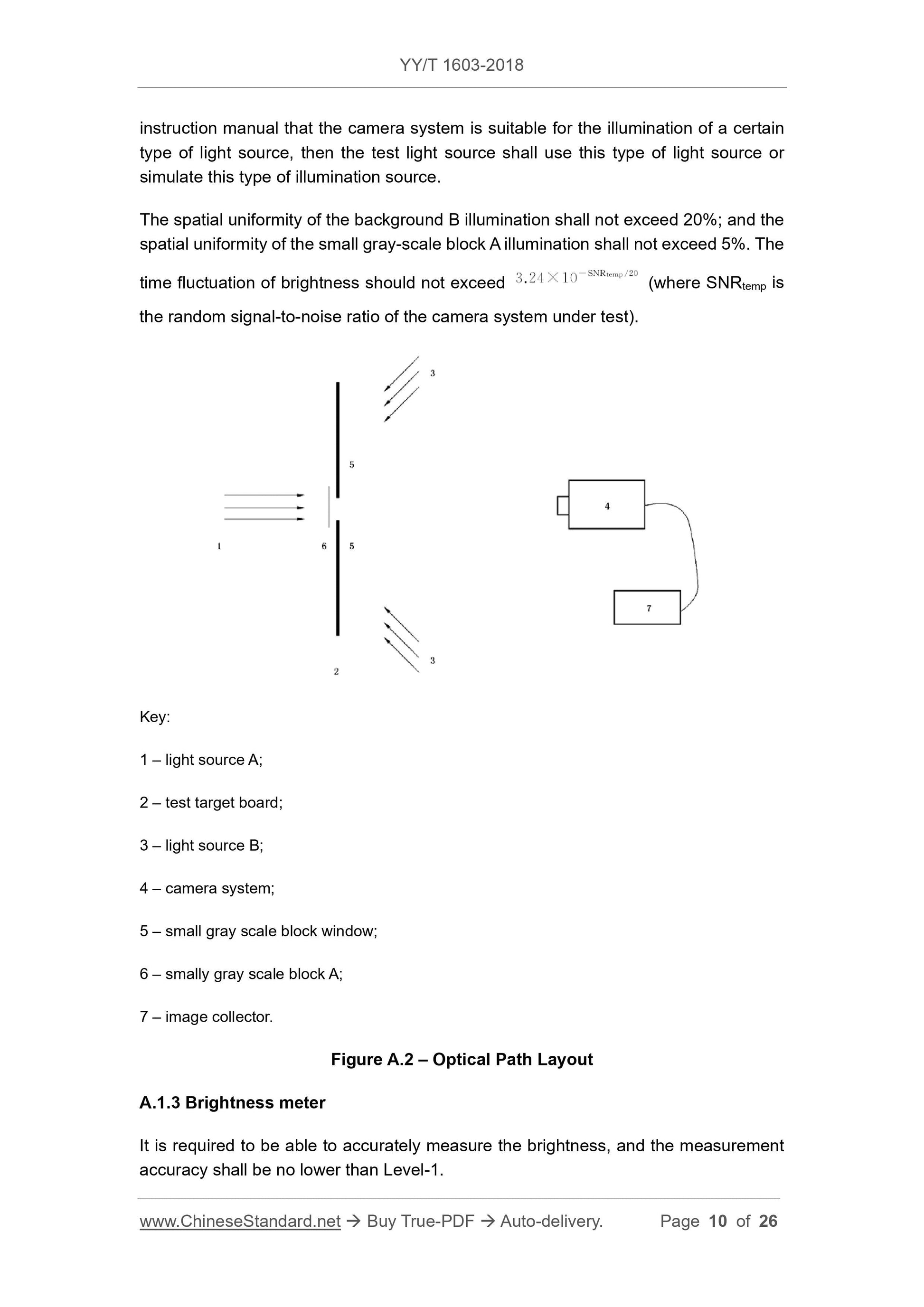
A.1.4 Image collector
It is required to be able to nondestructively collect and save image data in various
encoding modes.
A.2 Procedures
A.2.1 Test conditions
The temperature of the test environment is (23±2) °C, and the relative humidity is
(50±20) %.
The dark illumination of the test environment is no more than 1lx.
The power supply voltage stability of the control light source shall be controlled within
±2%.
The light source shall be fully preheated and stable.
A.2.2 Test process
A.2.2.1 White balance
For the camera system with white balance function, use A.1.1 test target board to
perform white balance under test conditions.
A.2.2.2 Viewfinder of camera system
Adjust the shooting distance to the desired position and record it as the measurement
working distance d0. For a camera system suitable for visual observation of
endoscopes, d0 is 500mm; other d0 is the design working distance. For zoomable
lenses, measure at the minimum focal length.
A.2.2.3 Focus
If the camera system has an autofocus function, the focus can be slightly blurred when
shooting the test target board to reduce the noise generated by the texture of the block
itself. The emphasis here is "slightly", and the boundaries between blocks shall be
clearly distinguished.
A.2.2.4 Set the brightness of background B on the test target board
Adjust the brightness of background B on the test target board to achieve the
brightness value specified by the manufacturer. During the entire brightness
adjustment process of small grays-sale block A, the brightness of background B shall
keep the overall gain of the tested camera system unchanged.
A.2.2.5 Adjust the brightness of small gray scale block A on the test target board,
Appendix B
(Normative)
Test Methods of Signal-to-Noise Ratio
B.1 Device
B.1.1 Test target board
The same as A.1.1.
B.1.2 Light source
The same as A.1.2.
B.1.3 Image collector
The same as A.1.4.
B.2 Procedure
B.2.1 Test conditions
The same as A.2.1.
B.2.2 Test process
B.2.2.1 White balance
The same as A.2.2.1.
B.2.2.2 Viewfind...
Get QUOTATION in 1-minute: Click YY/T 1603-2018
Historical versions: YY/T 1603-2018
Preview True-PDF (Reload/Scroll if blank)
YY/T 1603-2018: Medical endoscopes--Endoscope supply units--Video camera system
YY/T 1603-2018
YY
PHARMACEUTICAL INDUSTRY STANDARD
OF THE PEOPLE’S REPUBLIC OF CHINA
ICS 11.040.99
C 40
Medical Endoscopes - Endoscope Supply Units -
Video Camera System
ISSUED ON: JANUARY 19, 2018
IMPLEMENTED ON: JANUARY 01, 2019
Issued by: China Food and Drug Administration
Table of Contents
Foreword ... 3
1 Scope ... 4
2 Normative References ... 4
3 Terms and Definitions ... 4
4 requirements ... 6
5 Test Methods ... 7
Appendix A (Normative) Test Methods of Brightness Response Characteristic 9
Appendix B (Normative) Test Methods of Signal-to-Noise Ratio ... 14
Appendix C (Normative) Test Methods of Spatial Frequency Response ... 18
Appendix D (Normative) Test Methods of Static Image Latitude ... 24
Medical Endoscopes - Endoscope Supply Units -
Video Camera System
1 Scope
This Standard specifies the terms, definitions, requirements, and test methods for
medical endoscopic camera system.
This Standard is applicable to medical endoscopic camera system (hereinafter referred
to as camera system) that are used as endoscope supply units in endoscopy and
surgery.
This Standard is not applicable to the camera system with special spectral effects and
non-visible spectral imaging.
2 Normative References
The following documents are essential to the application of this document. For the
dated documents, only the versions with the dates indicated are applicable to this
document; for the undated documents, only the latest version (including all the
amendments) are applicable to this document.
GB 9706.19 Medical Electrical Equipment - Part 2: Particular Requirements for the
Safety of Endoscopic Equipment
3 Terms and Definitions
For the purpose of this document, the following terms and definitions apply.
3.1 Conversion function
3.1.1 Opto-electronic conversion function; OECF
The ideal relationship between the object brightness and the corresponding output
signal of the camera system.
3.1.2 Electro-optical conversion function
The inverse function of OECF.
AND the ratio of the modulation degree of the output signal calculated by the OECF
inverse function to the modulation degree of the target object surface brightness.
3.7 Sine-based spatial frequency response; s-SFR
SFR when the target is a sine wave modulation diagram.
3.8 Modulation degree
The ratio BETWEEN the maximum signal value minus the minimum signal value AND
the maximum signal value plus the minimum signal value.
3.9 Spectral neutrality
The reflection or transmission characteristics that is maintained constant against a
certain wavelength of light.
4 requirements
4.1 Requirements for detachable lens
4.1.1 Modulation transfer function (MTF)
The manufacturer shall give the nominal value of the spatial frequency corresponding
to the MTF value of the detachable lens at 50% in the attached information, the
tolerance is -20%, and the upper limit is not counted.
4.1.2 Focal length
The manufacturer shall provide the focal length parameters of the detachable lens in
the attached information. For the lens with a fixed focal length, the tolerance for
nominal value of the focal length is ±20%. For the lens with variable magnification, the
tolerance for nominal value of the minimum focal length is +20%, and the lower limit is
not counted; the tolerance for nominal value of the maximum focal length is -20%, and
the upper limit is not counted.
4.2 Brightness response characteristics
The manufacturer shall provide the output brightness electro-optical conversion
function or data list of the adapted monitor expressed in relative value in the technical
data. The sampling points of the data list are no less than 10, and cover the entire
latitude area.
The output signal of the camera system shall maintain a good linearity between the
brightness calculated according to the electro-optical characteristics and the
brightness of each gray scale of the actual tested target board; and the linear fitting
5.1.1 Modulation transfer function (MTF)
Place a Φ10mm aperture in the measuring optical path, then measure by a general-
purpose device with sufficient accuracy.
5.1.2 Focal length
Place a Φ10mm aperture in the measuring optical path, then measure by a focal length
meter with sufficient accuracy.
5.2 Test methods of brightness response characteristic
Check the content of the technical data provided by the manufacturer.
Measure the brightness response characteristics of the camera system according to
the methods specified in Appendix A.
5.3 Test methods of signal-to-noise ratio
Check the content of the technical data provided by the manufacturer.
Measure the signal-to-noise ratio of the camera system according to the methods
specified in Appendix B.
5.4 Test methods of spatial frequency response
Check the contents of the attached information provided by the manufacturer.
Measure the spatial frequency response of the camera system according to the
methods specified in Appendix C.
5.5 Test methods of static image latitude
Check the contents of the attached information provided by the manufacturer.
Measure the static image latitude of the camera system according to the methods
specified in Appendix D.
5.6 Electrical safety
It shall be carried out in accordance with the test method specified in GB 9706.19.
A.1.4 Image collector
It is required to be able to nondestructively collect and save image data in various
encoding modes.
A.2 Procedures
A.2.1 Test conditions
The temperature of the test environment is (23±2) °C, and the relative humidity is
(50±20) %.
The dark illumination of the test environment is no more than 1lx.
The power supply voltage stability of the control light source shall be controlled within
±2%.
The light source shall be fully preheated and stable.
A.2.2 Test process
A.2.2.1 White balance
For the camera system with white balance function, use A.1.1 test target board to
perform white balance under test conditions.
A.2.2.2 Viewfinder of camera system
Adjust the shooting distance to the desired position and record it as the measurement
working distance d0. For a camera system suitable for visual observation of
endoscopes, d0 is 500mm; other d0 is the design working distance. For zoomable
lenses, measure at the minimum focal length.
A.2.2.3 Focus
If the camera system has an autofocus function, the focus can be slightly blurred when
shooting the test target board to reduce the noise generated by the texture of the block
itself. The emphasis here is "slightly", and the boundaries between blocks shall be
clearly distinguished.
A.2.2.4 Set the brightness of background B on the test target board
Adjust the brightness of background B on the test target board to achieve the
brightness value specified by the manufacturer. During the entire brightness
adjustment process of small grays-sale block A, the brightness of background B shall
keep the overall gain of the tested camera system unchanged.
A.2.2.5 Adjust the brightness of small gray scale block A on the test target board,
Appendix B
(Normative)
Test Methods of Signal-to-Noise Ratio
B.1 Device
B.1.1 Test target board
The same as A.1.1.
B.1.2 Light source
The same as A.1.2.
B.1.3 Image collector
The same as A.1.4.
B.2 Procedure
B.2.1 Test conditions
The same as A.2.1.
B.2.2 Test process
B.2.2.1 White balance
The same as A.2.2.1.
B.2.2.2 Viewfind...
Share