PayPal, credit cards. Download editable-PDF & invoice in 1 second!
YY/T 1694-2020 English PDF (YYT1694-2020)
YY/T 1694-2020 English PDF (YYT1694-2020)
Precio habitual
$145.00 USD
Precio habitual
Precio de oferta
$145.00 USD
Precio unitario
/
por
Los gastos de envío se calculan en la pantalla de pago.
No se pudo cargar la disponibilidad de retiro
Delivery: 3 seconds. Download true-PDF + Invoice.
Get QUOTATION in 1-minute: Click YY/T 1694-2020
Historical versions: YY/T 1694-2020
Preview True-PDF (Reload/Scroll if blank)
YY/T 1694-2020: Optical positioning device for radiation therapy--Performance and test methods
YY/T 1694-2020
YY
PHARMACEUTICALS INDUSTRY STANDARD
OF THE PEOPLE’S REPUBLIC OF CHINA
ICS 11.040.60
C 43
Optical positioning device for radiation therapy –
Performance and test methods
ISSUED ON: FEBRUARY 21, 2020
IMPLEMENTED ON: JUNE 01, 2021
Issued by: National Medical Products Administration
Table of Contents
Foreword ... 3
1 Scope ... 4
2 Normative references ... 4
3 Terms and definitions ... 4
4 Requirements ... 4
4.1 Accompanying documents ... 4
4.2 Field of view ... 5
4.3 Positioning accuracy ... 6
4.4 Position repeatability ... 6
4.5 System data refresh frequency ... 6
4.6 Drift ... 6
4.7 Equipment functions ... 6
5 Test method ... 7
5.1 Accompanying documents ... 7
5.2 Field of view ... 7
5.3 Positioning accuracy ... 7
5.4 Positioning repeatability ... 9
5.5 System data refresh frequency ... 10
5.6 Drift ... 10
5.7 Device functions ... 10
Appendix A (Informative) Application descriptions for optical positioning device ... 11
Optical positioning device for radiation therapy –
Performance and test methods
1 Scope
This standard specifies the performance and test methods of optical positioning device
for radiation therapy.
This standard applies to the optical positioning device for radiation therapy, by optical
methods (including visible light, infrared light, laser, etc.).
2 Normative references
The following documents are essential to the application of this document. For the dated
documents, only the versions with the dates indicated are applicable to this document;
for the undated documents, only the latest version (including all the amendments) is
applicable to this standard.
GB/T 18987-2015 Radiotherapy equipment - Coordinates, movements and scales
3 Terms and definitions
The following terms and definitions apply to this document.
3.1
Isocenter
In radiology equipment, the reference axes of various movements move around a
common center point, meanwhile the radiation beam passes through the smallest
sphere centered on this point, which is the isocenter.
[GB/T 17857-1999, definition 3.2.50]
4 Requirements
4.1 Accompanying documents
Accompanying documents shall contain the following:
a) Model and manufacturer;
b) Type of imaging detection equipment;
c) Positioning method and type (such as using infrared light, visible light, etc.);
d) Registration algorithms and/or methods;
e) The coordinate system used, as well as the conversion relationship between the
coordinate system and the coordinate system specified in the GB/T 18987-2015
system;
f) Field of view;
g) Quality control methods (at least including self-calibration methods), frequency
and tools used;
Note: The quality control content of factors affecting positioning accuracy other than
optical positioning device (see Appendix A) is not within the scope of this standard.
h) Typical test conditions for positioning correction (including but not limited to: CT
planning image scanning conditions, reference images, image reconstruction
algorithms, image registration algorithms, etc.);
Note: Typical test conditions are a group of commonly used clinical test conditions.
i) If a marker is used, its possible influence on the therapeutic radiation shall be
indicated;
j) Equipment warm-up (stabilization) time;
k) Basic parameters of the light source used;
l) Installation requirements for optical positioning device, that is, installation
deviation requirements between the reference point of the optical positioning
device and the isocenter or reference point of the treatment equipment;
m) Refresh frequency of optical positioning device.
4.2 Field of view
The technical requirements for medical device products shall specify the field of view
of the optical positioning device in the three directions of X, Y, Z.
information, plan information, relationship between positioning marks and positioning
reference points, treatment progress.
c) Positioning and monitoring
It shall have the following functions:
1) Collect and store body surface information;
2) Record the positioning deviation during the treatment.
d) Data report output
It shall be able to output data and generate documentation.
5 Test method
5.1 Accompanying documents
Check the accompanying documents, which shall meet the requirements of 4.1.
5.2 Field of view
Place the markers, according to the manufacturer's requirements. Move the markers
along the two directions of the X-axis. Use the optical positioning device, to
continuously record the coordinates of the markers. Find the coordinates of the two
farthest markers in the direction of the X-axis. Then use this method, to find the
coordinate values of the two farthest markers in the direction of the Y axis and the Z
axis, respectively.
According to the coordinate values of the two farthest markers in the three directions
of X-axis, Y-axis, Z-axis, obtain the field of view of the optical positioning device; the
results shall meet the requirements of 4.2.
5.3 Positioning accuracy
5.3.1 Test phantom
a) Basic requirements
The following conditions shall be met:
1) Due to the different markers and identification technologies used in the optical
positioning device, this test allows the use of different types of phantoms; the
selection of simulation models shall meet the requirements of this test
verification.
2) The simulation model shall at least have the corresponding body surface
structure, so as to be able to simulate the use situation of clinical optical
positioning device.
b) Setting of marker points
Set 5 marker points in the simulation model, one of which is located at the
approximate center of the simulation model, denoted as P0 (x0, y0, z0). The other
4 marker points are not coplanar; the coordinate positions are fixed relative to P0
(x0, y0, z0), denoted as Pi (xi, yi, zi), i = 1, 2, 3, 4; the relative distance between
each point and P0 is not less than 25 mm.
5.3.2 Test method
Under the typical test conditions specified by the manufacturer, to carry out the test, in
accordance with the following steps:
a) Fix the simulation model on the CT bed. Scan according to the typical scanning
conditions, which is specified by the optical positioning device manufacturer, to
obtain CT images.
b) Select a typical reference image reconstruction algorithm, to reconstruct the CT
image obtained above. Select the P0 (x0, y0, z0) point in the simulation model, as
the target point.
c) Start the optical positioning device.
d) Adjust the simulation model. Place the marker point P0 of the simulation model
at the approximate isocenter (or treatment reference point). Detect and record the
coordinates of the marker point P0 as R0,0 (x0,0, y0,0, z0,0); the coordinates of the
other four points are Ri,0 (xi,0, yi,0, zi,0), i = 1, 2, 3, 4.
e) Translate the simulation model by Δd (d, d, d).
Note: d is 15 mm.
f) Detect and record the coordinates of the marker point P0 as R0,1 (x0,1, y0,1, z0,1); the
coordinates of the other four points are Ri,1 (xi,1, yi,1, zi,1), i = 1, 2, 3, 4.
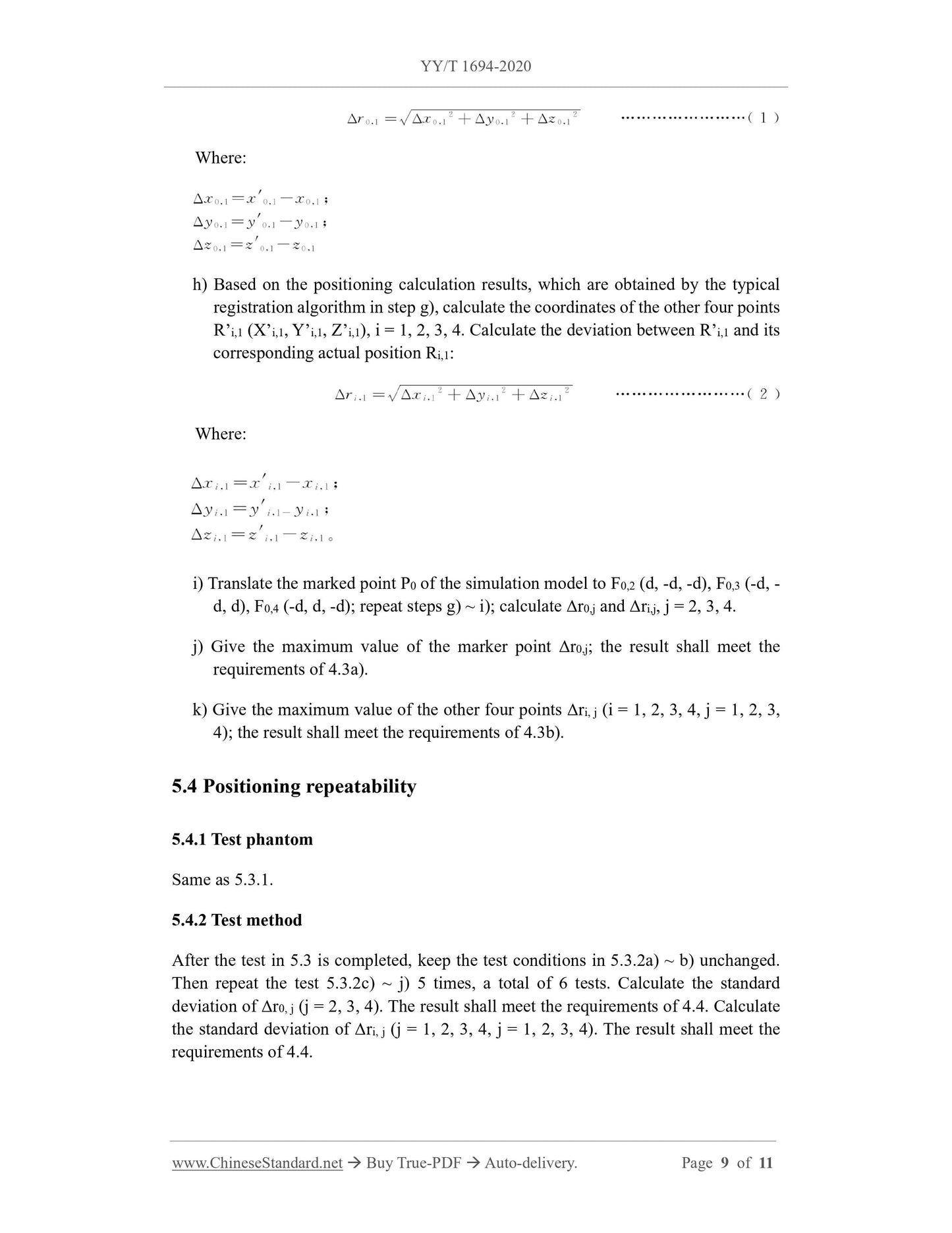
g) Perform positioning calculation, through a typical registration algorithm, to obtain
the coordinates R’0,1 (x’0,1, y’0,1, z’0,1) of the marked point P0. Calculate the
deviation -- between R’0,1 and its corresponding actual position R0,1, according to
formula (1):
5.5 System data refresh frequency
5.5.1 Test phantom
Same as 5.3.1. ...
Get QUOTATION in 1-minute: Click YY/T 1694-2020
Historical versions: YY/T 1694-2020
Preview True-PDF (Reload/Scroll if blank)
YY/T 1694-2020: Optical positioning device for radiation therapy--Performance and test methods
YY/T 1694-2020
YY
PHARMACEUTICALS INDUSTRY STANDARD
OF THE PEOPLE’S REPUBLIC OF CHINA
ICS 11.040.60
C 43
Optical positioning device for radiation therapy –
Performance and test methods
ISSUED ON: FEBRUARY 21, 2020
IMPLEMENTED ON: JUNE 01, 2021
Issued by: National Medical Products Administration
Table of Contents
Foreword ... 3
1 Scope ... 4
2 Normative references ... 4
3 Terms and definitions ... 4
4 Requirements ... 4
4.1 Accompanying documents ... 4
4.2 Field of view ... 5
4.3 Positioning accuracy ... 6
4.4 Position repeatability ... 6
4.5 System data refresh frequency ... 6
4.6 Drift ... 6
4.7 Equipment functions ... 6
5 Test method ... 7
5.1 Accompanying documents ... 7
5.2 Field of view ... 7
5.3 Positioning accuracy ... 7
5.4 Positioning repeatability ... 9
5.5 System data refresh frequency ... 10
5.6 Drift ... 10
5.7 Device functions ... 10
Appendix A (Informative) Application descriptions for optical positioning device ... 11
Optical positioning device for radiation therapy –
Performance and test methods
1 Scope
This standard specifies the performance and test methods of optical positioning device
for radiation therapy.
This standard applies to the optical positioning device for radiation therapy, by optical
methods (including visible light, infrared light, laser, etc.).
2 Normative references
The following documents are essential to the application of this document. For the dated
documents, only the versions with the dates indicated are applicable to this document;
for the undated documents, only the latest version (including all the amendments) is
applicable to this standard.
GB/T 18987-2015 Radiotherapy equipment - Coordinates, movements and scales
3 Terms and definitions
The following terms and definitions apply to this document.
3.1
Isocenter
In radiology equipment, the reference axes of various movements move around a
common center point, meanwhile the radiation beam passes through the smallest
sphere centered on this point, which is the isocenter.
[GB/T 17857-1999, definition 3.2.50]
4 Requirements
4.1 Accompanying documents
Accompanying documents shall contain the following:
a) Model and manufacturer;
b) Type of imaging detection equipment;
c) Positioning method and type (such as using infrared light, visible light, etc.);
d) Registration algorithms and/or methods;
e) The coordinate system used, as well as the conversion relationship between the
coordinate system and the coordinate system specified in the GB/T 18987-2015
system;
f) Field of view;
g) Quality control methods (at least including self-calibration methods), frequency
and tools used;
Note: The quality control content of factors affecting positioning accuracy other than
optical positioning device (see Appendix A) is not within the scope of this standard.
h) Typical test conditions for positioning correction (including but not limited to: CT
planning image scanning conditions, reference images, image reconstruction
algorithms, image registration algorithms, etc.);
Note: Typical test conditions are a group of commonly used clinical test conditions.
i) If a marker is used, its possible influence on the therapeutic radiation shall be
indicated;
j) Equipment warm-up (stabilization) time;
k) Basic parameters of the light source used;
l) Installation requirements for optical positioning device, that is, installation
deviation requirements between the reference point of the optical positioning
device and the isocenter or reference point of the treatment equipment;
m) Refresh frequency of optical positioning device.
4.2 Field of view
The technical requirements for medical device products shall specify the field of view
of the optical positioning device in the three directions of X, Y, Z.
information, plan information, relationship between positioning marks and positioning
reference points, treatment progress.
c) Positioning and monitoring
It shall have the following functions:
1) Collect and store body surface information;
2) Record the positioning deviation during the treatment.
d) Data report output
It shall be able to output data and generate documentation.
5 Test method
5.1 Accompanying documents
Check the accompanying documents, which shall meet the requirements of 4.1.
5.2 Field of view
Place the markers, according to the manufacturer's requirements. Move the markers
along the two directions of the X-axis. Use the optical positioning device, to
continuously record the coordinates of the markers. Find the coordinates of the two
farthest markers in the direction of the X-axis. Then use this method, to find the
coordinate values of the two farthest markers in the direction of the Y axis and the Z
axis, respectively.
According to the coordinate values of the two farthest markers in the three directions
of X-axis, Y-axis, Z-axis, obtain the field of view of the optical positioning device; the
results shall meet the requirements of 4.2.
5.3 Positioning accuracy
5.3.1 Test phantom
a) Basic requirements
The following conditions shall be met:
1) Due to the different markers and identification technologies used in the optical
positioning device, this test allows the use of different types of phantoms; the
selection of simulation models shall meet the requirements of this test
verification.
2) The simulation model shall at least have the corresponding body surface
structure, so as to be able to simulate the use situation of clinical optical
positioning device.
b) Setting of marker points
Set 5 marker points in the simulation model, one of which is located at the
approximate center of the simulation model, denoted as P0 (x0, y0, z0). The other
4 marker points are not coplanar; the coordinate positions are fixed relative to P0
(x0, y0, z0), denoted as Pi (xi, yi, zi), i = 1, 2, 3, 4; the relative distance between
each point and P0 is not less than 25 mm.
5.3.2 Test method
Under the typical test conditions specified by the manufacturer, to carry out the test, in
accordance with the following steps:
a) Fix the simulation model on the CT bed. Scan according to the typical scanning
conditions, which is specified by the optical positioning device manufacturer, to
obtain CT images.
b) Select a typical reference image reconstruction algorithm, to reconstruct the CT
image obtained above. Select the P0 (x0, y0, z0) point in the simulation model, as
the target point.
c) Start the optical positioning device.
d) Adjust the simulation model. Place the marker point P0 of the simulation model
at the approximate isocenter (or treatment reference point). Detect and record the
coordinates of the marker point P0 as R0,0 (x0,0, y0,0, z0,0); the coordinates of the
other four points are Ri,0 (xi,0, yi,0, zi,0), i = 1, 2, 3, 4.
e) Translate the simulation model by Δd (d, d, d).
Note: d is 15 mm.
f) Detect and record the coordinates of the marker point P0 as R0,1 (x0,1, y0,1, z0,1); the
coordinates of the other four points are Ri,1 (xi,1, yi,1, zi,1), i = 1, 2, 3, 4.
g) Perform positioning calculation, through a typical registration algorithm, to obtain
the coordinates R’0,1 (x’0,1, y’0,1, z’0,1) of the marked point P0. Calculate the
deviation -- between R’0,1 and its corresponding actual position R0,1, according to
formula (1):
5.5 System data refresh frequency
5.5.1 Test phantom
Same as 5.3.1. ...
Share