1
/
/
12
PayPal, credit cards. Download editable-PDF and invoice in 1 second!
YD/T 3695-2020 English PDF (YDT3695-2020)
YD/T 3695-2020 English PDF (YDT3695-2020)
Normaalihinta
$500.00 USD
Normaalihinta
Alennushinta
$500.00 USD
Yksikköhinta
/
kohti
Toimituskulut lasketaan kassalla.
Noudon saatavuutta ei voitu ladata
Delivery: 3 seconds. Download true-PDF + Invoice.
Get Quotation: Click YD/T 3695-2020 (Self-service in 1-minute)
Historical versions (Master-website): YD/T 3695-2020
Preview True-PDF (Reload/Scroll-down if blank)
YD/T 3695-2020: Vehicle Emergency Alarm System Based on Public Telecommunication Network Wireless Data Transmission Technology Requirements
YD/T 3695-2020
YD
COMMUNICATIONS INDUSTRY STANDARD
OF THE PEOPLE’S REPUBLIC OF CHINA
ICS 33.060.99
M36
Vehicle Emergency Alarm System Based on Public
Telecommunication Network Wireless Data Transmission
Technology Requirements
ISSUED ON: APRIL 16, 2020
IMPLEMENTED ON: JULY 01, 2020
Issued by: Ministry of Industry and Information Technology of the People's
Republic of China.
Table of Contents
Foreword ... 3
1 Scope ... 5
2 Normative references ... 5
3 Terms, definitions and abbreviations ... 6
3.1 Terms and definitions ... 6
3.2 Abbreviations ... 7
4 Overviews ... 8
4.1 Overview of eCall system ... 8
4.2 eCall system requirements ... 8
4.3 eCall in-band modulation architecture ... 10
5 Functional description of IVS data modem ... 13
5.1 IVS transmitter ... 13
5.2 IVS receiver ... 21
6 Functional description of data modem ... 24
6.1 PSAP transmitter ... 24
6.2 PSAP receiver ... 29
7 Transport protocols and error handling ... 32
7.1 Normal operation ... 32
7.2 Abnormal operation ... 32
7.3 PSAP and IVS protocol state model ... 36
Annex A (informative) eCall performance requirements/goals and design constraints
... 39
Vehicle Emergency Alarm System Based on Public
Telecommunication Network Wireless Data Transmission
Technology Requirements
1 Scope
This Standard specifies the technical requirements for communication and data
transmission of the vehicle emergency alarm system based on public
telecommunication network, namely the overall scheme and algorithm description of
eCall in-band modulation, including the IVS modem and PSAP modem that constitute
full-duplex transmission.
This Standard applies to vehicle emergency alarm systems based on public
telecommunication network.
2 Normative references
The following referenced documents are indispensable for the application of this
document. For dated references, only the edition cited applies. For undated references,
the latest edition of the referenced document (including any amendments) applies.
3GPPTS 22.101, Service aspects; Service principles
3GPP TR 22.967, Transfer of ECall Data
3GPP TS 26.071, AMR speech Codec; General description
3GPP TS 26.094, Mandatory speech codec speech processing functions; Adaptive
Multi-Rate (AMR) speech codec; Voice Activity Detector (VAD)
3GPP TS 26.226, Cellular text telephone modem; General description
3GPP TS 26.268, eCall Data Transfer; In-band modem solution· ANSI-C reference
code
3GPP TS 26.269, eCall Data Transfer; In-band modem solution; Conformance
testing
3GPP TR 26.969, eCall Data Transfer; In-band modem solution; Characterization
report
3GPP TR 26.967, eCall Data Transfer; In-band modem solution
3GPPTS 46.001, Full rate speech: Processing functions
3GPP TS 46.032, Full rate speech; Voice Activity Detection (VAD) for full rate
speech traffic channels
3 Terms, definitions and abbreviations
3.1 Terms and definitions
For the purposes of this document, the following terms and definitions apply.
3.1.1 eCall
An emergency call initiated from the vehicle manually or automatically. The call also
carries the minimum set of data (MSD) associated with the emergency call.
3.1.2 eCall In-band Modem
A pair of modems (constituting the transmitter and receiver of the IVS and PSAP)
operate in full-duplex mode to reliably transmit the eCall minimum set of data (MSD)
from the IVS to the PSAP via the eCall voice channels of the cellular and PSTN.
3.1.3 feedback frame
It includes the downlink signal transmission time of the feedback data. The duration is
140 ms. This is equivalent to a total of 1120 samples at an 8 kHz sampling rate.
3.1.4 frame (or: speech frame)
Equivalent to 20 ms duration (equivalent to one AMR or FR speech frame length, i.e.
160 samples at 8 kHz sampling rate).
3.1.5 MSD
The minimum set of data that is part of the eCall data sent from the vehicle to the public
safety response center or other designated eCall center. The maximum MSD is 140
bytes and includes information such as vehicle identification, vehicle location
information, and timestamp.
3.1.6 MSD data frame
It includes the uplink signal transmission time of one MSD data (after synchronization
is established). The duration is 1320 ms. This is equivalent to a total of 10560 samples
at 8kHz sampling rate (if a fast modulator is used) or 18560 samples (if a reliable
modulator is used).
the originating and transmitting networks;
- The voice and data portions of an eCall shall be routed to the same PSAP or
designated eCall center;
- PSAP needs to confirm the received data and retransmit the data if necessary;
- If the UE is configured to transmit data only in eCalls (e.g. eCall only UE), the UE
shall not generate additional signaling to the network except for eCall related
signaling;
- The UE shall indicate whether the eCall carries relevant data when the call is
established.
In addition to the above general requirements, the following requirements must also be
met:
- There are two ways to initiate an eCall. One is automatic (e.g. due to a vehicle
collision) and the other is manual by a person in the vehicle;
- IVS or UE supporting eCall function shall carry an indication when establishing an
eCall to indicate whether the current call is manually initiated (MIeC) or
automatically initiated (AIeC);
- The size of the minimum data set (MSD) sent by the IVS to the network shall not
exceed 140 bytes;
- PSAP shall receive MSD within 4 s after the end-to-end link is established;
- In the event that the MSD is not included in the eCall or the MSD is damaged or
lost, the voice eCall function shall not be affected;
- During MSD transmission, the user shall be provided with call progress prompts;
- To reduce the eCall establishment time, the IVS working in eCall only mode can
still receive information about whether the network is available even if the
corresponding PLMN registration is not completed;
- The network can use the eCall indication during the eCall establishment process to
distinguish the type of eCall;
- MieC and AIeC can be used to filter or route corresponding eCalls to dedicated
PSAP operators.
Throughout the eCall process and after the PSAP receives the MSD, the PSAP shall be
allowed to send an acknowledgment to the IVS to indicate that the MSD has been
received. The PSAP shall be allowed to request the IVS to resend the latest MSD. The
PSAP shall be allowed to direct the IVS to terminate the call.
To select a better eCall in-band modulation scheme, Annex A provides more detailed
business requirements, performance requirements under different wireless channels,
and design constraints.
4.3 eCall in-band modulation architecture
4.3.1 General
The eCall in-band modulation scheme specified in this Standard consists of an IVS data
modem and a PSAP data modem. The signal design used allows the signal to pass
through the voice vocoder with only moderate distortion and provide sufficient data rate
to meet the requirements of transmitting MSD as quickly as possible.
Figure 2 shows the overall cellular system architecture including IVS and PSAP data
modem. The specific process includes the following steps.
After a voice eCall is established (either automatically or manually), the IVS receiver
continuously monitors the incoming signal from the voice decoder. Upon detecting an
MSD request from the PSAP, the IVS connects the transmit side of the IVS data modem
to the input of the voice encoder and mutes all subsequent voice signal input generated
during the MSD transmission period to avoid interference with the eCall data
transmission. There is also another case where the MSD transmission is triggered by
the IVS. In this case, the IVS notifies the PSAP, which then requests the IVS to send
the MSD. In general, as long as the eCall modem activates transmission, the
microphone is disconnected from the actual transmission path of the signal.
The first operation mode can be called pull mode. The second is push mode. In push
mode, the IVS initiates a request to the PSAP to request MSD data.
The specific configuration of push mode or pull mode is not within the scope of this
Standard. Refer to 4.2 for related eCall business requirements.
The operating principles of the IVS and PSAP modems shown in Figure 2 are described
in detail below. The specific algorithms and functions will be explained in Chapters 5
and 6.
6.2.2 Synchronous detection and tracking
In general, uplink synchronization detection and tracking are similar to those described
in 5.2.2. The main differences are as follows.
The PSAP is triggered by detecting a synchronization preamble. After detecting the
preamble, the synchronization module continuously checks the received signal in
another 10 voice frames to ensure that the synchronization module has not found a more
reliable preamble signal to avoid false detection and incorrect delay estimation. If the
synchronization module finds a better preamble signal, it re-receives the MSD.
The synchronization check function continuously checks the validity of the calculated
delay estimate based on subsequent uplink synchronization segments. If the delay
estimate is found to be invalid, the synchronization tracking module searches for a new
valid delay estimate in a predetermined search window. The maximum search window
on the PSAP receiver side is +/-240 samples. If the synchronization tracking module
fails to find a new valid delay value in a number of subsequent synchronization
segments (default is 4), the PSAP transmitter resets. A START message is sent to the
IVS to restart the MSD transmission.
The tone detection function module estimates the frequency of the synchronization tone
using the DFT method to estimate two reference frequencies. If the frequency can be
reliably detected, it is used to determine which demodulator to use for demodulation. If
it cannot be detected, if it is the first time the preamble is detected, a fast modulation
scheme is used for demodulation, otherwise, a reliable demodulation scheme is used
for demodulation.
6.2.3 Timing unit
See 5.2.2.
6.2.4 Demultiplexing
See 5.2.3.
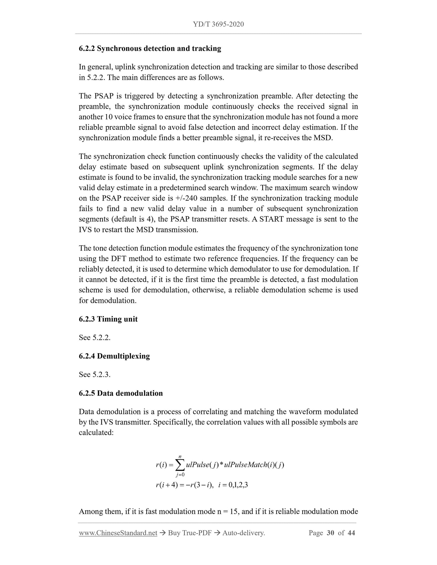
6.2.5 Data demodulation
Data demodulation is a process of correlating and matching the waveform modulated
by the IVS transmitter. Specifically, the correlation values with all possible symbols are
calculated:
Among them, if it is fast modulation mode n = 15, and if it is reliable modulation mode
with the description in 5.2. If two correct synchronization preambles and a subsequent
push message are detected, it means that a push command has been detected.
7 Transport protocols and error handling
7.1 Normal operation
The previous sections describe the eCall data transmission operation under normal
circumstances.
After the operator requests or receives a push message from the IVS, the PSAP
transmitter starts sending START messages. The IVS receiver shall obtain
synchronization by detecting the synchronization preamble sent with the START
message, which allows the IVS receiver to demodulate the START message. The PSAP
transmitter continues to send START messages to the IVS. The number of times it is
allowed to send START messages is determined by the higher-level protocol and the
timer (not defined in this Standard).
Once the START message is detected, the IVS starts sending the sync frame and the
first MSD message (using redundancy version rv0). The PSAP shall detect the sync
frame and get accurate synchronization based on the sync preamble, and then the PSAP
receiver can correctly demodulate and decode the MSD message.
Once the PSAP receiver is synchronized, the PSAP starts to send NACK messages
repeatedly, which the IVS shall detect. Subsequently, the IVS sends MSD data. After
sending MSD rv0, the IVS continues to send the next redundant version of the same
MSD message rv1, rv2, and so on.
PSAP demodulates MSD rv0 and performs CRC check. If CRC check fails, PSAP
continues to send NACK messages. If successful, PSAP sends link layer ACK or high
layer ACK message (it is determined by the high layer protocol whether to send link
layer or high layer ACK). For safety reasons, from the perspective of the modem
protocol, at least 5 ACK messages of the same type (link layer or high layer) need to be
sent. High layer ACK shall not be sent before link layer ACK. Link layer ACK shall not
be sent after high layer ACK message. For this purpose, the reference modem
implementation sends 5 link layer ACK messages until a trigger from the high layer
protocol is received, and then sends 5 high layer ACK messages. IVS shall be able to
detect a specific ACK (link layer or high layer), and then it stops sending MSD.
7.2 Abnormal operation
This section describes some abnormal situations that occur due to severe signal
distortion caused by the transmission channel. These situations need to be handled by
the overall transmission protocol to avoid deadlock situations. It shall be noted that the
Annex A
(informative)
eCall performance requirements/goals and design constraints
The minimum performance requirements for an imprecise implementation of the eCall
modem and the exact performance of a precise implementation are defined in another
conformance test document.
A.1 Definition
eCall candidate solutions shall meet the performance requirements, otherwise they will
not be considered.
NOTE: Performance requirements include all business requirements.
The performance goals do not set exact limits, but can be used to rank candidate
technologies based on the defined criteria.
Design constraints provide upper limits (requirements and goals), e.g. on algorithmic
complexity.
Solution selection selects candidate solutions based on performance requirements and
design constraints. Then sort them according to performance goals and select the best
candidate solution.
eCall protocols refer to all application layer protocols between IVS and PSAP, while
the selected ...
Get Quotation: Click YD/T 3695-2020 (Self-service in 1-minute)
Historical versions (Master-website): YD/T 3695-2020
Preview True-PDF (Reload/Scroll-down if blank)
YD/T 3695-2020: Vehicle Emergency Alarm System Based on Public Telecommunication Network Wireless Data Transmission Technology Requirements
YD/T 3695-2020
YD
COMMUNICATIONS INDUSTRY STANDARD
OF THE PEOPLE’S REPUBLIC OF CHINA
ICS 33.060.99
M36
Vehicle Emergency Alarm System Based on Public
Telecommunication Network Wireless Data Transmission
Technology Requirements
ISSUED ON: APRIL 16, 2020
IMPLEMENTED ON: JULY 01, 2020
Issued by: Ministry of Industry and Information Technology of the People's
Republic of China.
Table of Contents
Foreword ... 3
1 Scope ... 5
2 Normative references ... 5
3 Terms, definitions and abbreviations ... 6
3.1 Terms and definitions ... 6
3.2 Abbreviations ... 7
4 Overviews ... 8
4.1 Overview of eCall system ... 8
4.2 eCall system requirements ... 8
4.3 eCall in-band modulation architecture ... 10
5 Functional description of IVS data modem ... 13
5.1 IVS transmitter ... 13
5.2 IVS receiver ... 21
6 Functional description of data modem ... 24
6.1 PSAP transmitter ... 24
6.2 PSAP receiver ... 29
7 Transport protocols and error handling ... 32
7.1 Normal operation ... 32
7.2 Abnormal operation ... 32
7.3 PSAP and IVS protocol state model ... 36
Annex A (informative) eCall performance requirements/goals and design constraints
... 39
Vehicle Emergency Alarm System Based on Public
Telecommunication Network Wireless Data Transmission
Technology Requirements
1 Scope
This Standard specifies the technical requirements for communication and data
transmission of the vehicle emergency alarm system based on public
telecommunication network, namely the overall scheme and algorithm description of
eCall in-band modulation, including the IVS modem and PSAP modem that constitute
full-duplex transmission.
This Standard applies to vehicle emergency alarm systems based on public
telecommunication network.
2 Normative references
The following referenced documents are indispensable for the application of this
document. For dated references, only the edition cited applies. For undated references,
the latest edition of the referenced document (including any amendments) applies.
3GPPTS 22.101, Service aspects; Service principles
3GPP TR 22.967, Transfer of ECall Data
3GPP TS 26.071, AMR speech Codec; General description
3GPP TS 26.094, Mandatory speech codec speech processing functions; Adaptive
Multi-Rate (AMR) speech codec; Voice Activity Detector (VAD)
3GPP TS 26.226, Cellular text telephone modem; General description
3GPP TS 26.268, eCall Data Transfer; In-band modem solution· ANSI-C reference
code
3GPP TS 26.269, eCall Data Transfer; In-band modem solution; Conformance
testing
3GPP TR 26.969, eCall Data Transfer; In-band modem solution; Characterization
report
3GPP TR 26.967, eCall Data Transfer; In-band modem solution
3GPPTS 46.001, Full rate speech: Processing functions
3GPP TS 46.032, Full rate speech; Voice Activity Detection (VAD) for full rate
speech traffic channels
3 Terms, definitions and abbreviations
3.1 Terms and definitions
For the purposes of this document, the following terms and definitions apply.
3.1.1 eCall
An emergency call initiated from the vehicle manually or automatically. The call also
carries the minimum set of data (MSD) associated with the emergency call.
3.1.2 eCall In-band Modem
A pair of modems (constituting the transmitter and receiver of the IVS and PSAP)
operate in full-duplex mode to reliably transmit the eCall minimum set of data (MSD)
from the IVS to the PSAP via the eCall voice channels of the cellular and PSTN.
3.1.3 feedback frame
It includes the downlink signal transmission time of the feedback data. The duration is
140 ms. This is equivalent to a total of 1120 samples at an 8 kHz sampling rate.
3.1.4 frame (or: speech frame)
Equivalent to 20 ms duration (equivalent to one AMR or FR speech frame length, i.e.
160 samples at 8 kHz sampling rate).
3.1.5 MSD
The minimum set of data that is part of the eCall data sent from the vehicle to the public
safety response center or other designated eCall center. The maximum MSD is 140
bytes and includes information such as vehicle identification, vehicle location
information, and timestamp.
3.1.6 MSD data frame
It includes the uplink signal transmission time of one MSD data (after synchronization
is established). The duration is 1320 ms. This is equivalent to a total of 10560 samples
at 8kHz sampling rate (if a fast modulator is used) or 18560 samples (if a reliable
modulator is used).
the originating and transmitting networks;
- The voice and data portions of an eCall shall be routed to the same PSAP or
designated eCall center;
- PSAP needs to confirm the received data and retransmit the data if necessary;
- If the UE is configured to transmit data only in eCalls (e.g. eCall only UE), the UE
shall not generate additional signaling to the network except for eCall related
signaling;
- The UE shall indicate whether the eCall carries relevant data when the call is
established.
In addition to the above general requirements, the following requirements must also be
met:
- There are two ways to initiate an eCall. One is automatic (e.g. due to a vehicle
collision) and the other is manual by a person in the vehicle;
- IVS or UE supporting eCall function shall carry an indication when establishing an
eCall to indicate whether the current call is manually initiated (MIeC) or
automatically initiated (AIeC);
- The size of the minimum data set (MSD) sent by the IVS to the network shall not
exceed 140 bytes;
- PSAP shall receive MSD within 4 s after the end-to-end link is established;
- In the event that the MSD is not included in the eCall or the MSD is damaged or
lost, the voice eCall function shall not be affected;
- During MSD transmission, the user shall be provided with call progress prompts;
- To reduce the eCall establishment time, the IVS working in eCall only mode can
still receive information about whether the network is available even if the
corresponding PLMN registration is not completed;
- The network can use the eCall indication during the eCall establishment process to
distinguish the type of eCall;
- MieC and AIeC can be used to filter or route corresponding eCalls to dedicated
PSAP operators.
Throughout the eCall process and after the PSAP receives the MSD, the PSAP shall be
allowed to send an acknowledgment to the IVS to indicate that the MSD has been
received. The PSAP shall be allowed to request the IVS to resend the latest MSD. The
PSAP shall be allowed to direct the IVS to terminate the call.
To select a better eCall in-band modulation scheme, Annex A provides more detailed
business requirements, performance requirements under different wireless channels,
and design constraints.
4.3 eCall in-band modulation architecture
4.3.1 General
The eCall in-band modulation scheme specified in this Standard consists of an IVS data
modem and a PSAP data modem. The signal design used allows the signal to pass
through the voice vocoder with only moderate distortion and provide sufficient data rate
to meet the requirements of transmitting MSD as quickly as possible.
Figure 2 shows the overall cellular system architecture including IVS and PSAP data
modem. The specific process includes the following steps.
After a voice eCall is established (either automatically or manually), the IVS receiver
continuously monitors the incoming signal from the voice decoder. Upon detecting an
MSD request from the PSAP, the IVS connects the transmit side of the IVS data modem
to the input of the voice encoder and mutes all subsequent voice signal input generated
during the MSD transmission period to avoid interference with the eCall data
transmission. There is also another case where the MSD transmission is triggered by
the IVS. In this case, the IVS notifies the PSAP, which then requests the IVS to send
the MSD. In general, as long as the eCall modem activates transmission, the
microphone is disconnected from the actual transmission path of the signal.
The first operation mode can be called pull mode. The second is push mode. In push
mode, the IVS initiates a request to the PSAP to request MSD data.
The specific configuration of push mode or pull mode is not within the scope of this
Standard. Refer to 4.2 for related eCall business requirements.
The operating principles of the IVS and PSAP modems shown in Figure 2 are described
in detail below. The specific algorithms and functions will be explained in Chapters 5
and 6.
6.2.2 Synchronous detection and tracking
In general, uplink synchronization detection and tracking are similar to those described
in 5.2.2. The main differences are as follows.
The PSAP is triggered by detecting a synchronization preamble. After detecting the
preamble, the synchronization module continuously checks the received signal in
another 10 voice frames to ensure that the synchronization module has not found a more
reliable preamble signal to avoid false detection and incorrect delay estimation. If the
synchronization module finds a better preamble signal, it re-receives the MSD.
The synchronization check function continuously checks the validity of the calculated
delay estimate based on subsequent uplink synchronization segments. If the delay
estimate is found to be invalid, the synchronization tracking module searches for a new
valid delay estimate in a predetermined search window. The maximum search window
on the PSAP receiver side is +/-240 samples. If the synchronization tracking module
fails to find a new valid delay value in a number of subsequent synchronization
segments (default is 4), the PSAP transmitter resets. A START message is sent to the
IVS to restart the MSD transmission.
The tone detection function module estimates the frequency of the synchronization tone
using the DFT method to estimate two reference frequencies. If the frequency can be
reliably detected, it is used to determine which demodulator to use for demodulation. If
it cannot be detected, if it is the first time the preamble is detected, a fast modulation
scheme is used for demodulation, otherwise, a reliable demodulation scheme is used
for demodulation.
6.2.3 Timing unit
See 5.2.2.
6.2.4 Demultiplexing
See 5.2.3.
6.2.5 Data demodulation
Data demodulation is a process of correlating and matching the waveform modulated
by the IVS transmitter. Specifically, the correlation values with all possible symbols are
calculated:
Among them, if it is fast modulation mode n = 15, and if it is reliable modulation mode
with the description in 5.2. If two correct synchronization preambles and a subsequent
push message are detected, it means that a push command has been detected.
7 Transport protocols and error handling
7.1 Normal operation
The previous sections describe the eCall data transmission operation under normal
circumstances.
After the operator requests or receives a push message from the IVS, the PSAP
transmitter starts sending START messages. The IVS receiver shall obtain
synchronization by detecting the synchronization preamble sent with the START
message, which allows the IVS receiver to demodulate the START message. The PSAP
transmitter continues to send START messages to the IVS. The number of times it is
allowed to send START messages is determined by the higher-level protocol and the
timer (not defined in this Standard).
Once the START message is detected, the IVS starts sending the sync frame and the
first MSD message (using redundancy version rv0). The PSAP shall detect the sync
frame and get accurate synchronization based on the sync preamble, and then the PSAP
receiver can correctly demodulate and decode the MSD message.
Once the PSAP receiver is synchronized, the PSAP starts to send NACK messages
repeatedly, which the IVS shall detect. Subsequently, the IVS sends MSD data. After
sending MSD rv0, the IVS continues to send the next redundant version of the same
MSD message rv1, rv2, and so on.
PSAP demodulates MSD rv0 and performs CRC check. If CRC check fails, PSAP
continues to send NACK messages. If successful, PSAP sends link layer ACK or high
layer ACK message (it is determined by the high layer protocol whether to send link
layer or high layer ACK). For safety reasons, from the perspective of the modem
protocol, at least 5 ACK messages of the same type (link layer or high layer) need to be
sent. High layer ACK shall not be sent before link layer ACK. Link layer ACK shall not
be sent after high layer ACK message. For this purpose, the reference modem
implementation sends 5 link layer ACK messages until a trigger from the high layer
protocol is received, and then sends 5 high layer ACK messages. IVS shall be able to
detect a specific ACK (link layer or high layer), and then it stops sending MSD.
7.2 Abnormal operation
This section describes some abnormal situations that occur due to severe signal
distortion caused by the transmission channel. These situations need to be handled by
the overall transmission protocol to avoid deadlock situations. It shall be noted that the
Annex A
(informative)
eCall performance requirements/goals and design constraints
The minimum performance requirements for an imprecise implementation of the eCall
modem and the exact performance of a precise implementation are defined in another
conformance test document.
A.1 Definition
eCall candidate solutions shall meet the performance requirements, otherwise they will
not be considered.
NOTE: Performance requirements include all business requirements.
The performance goals do not set exact limits, but can be used to rank candidate
technologies based on the defined criteria.
Design constraints provide upper limits (requirements and goals), e.g. on algorithmic
complexity.
Solution selection selects candidate solutions based on performance requirements and
design constraints. Then sort them according to performance goals and select the best
candidate solution.
eCall protocols refer to all application layer protocols between IVS and PSAP, while
the selected ...
Share