1
/
de
8
PayPal, credit cards. Download editable-PDF and invoice in 1 second!
GB/T 5137.2-2020 English PDF (GBT5137.2-2020)
GB/T 5137.2-2020 English PDF (GBT5137.2-2020)
Prix habituel
$245.00 USD
Prix habituel
Prix promotionnel
$245.00 USD
Prix unitaire
/
par
Frais d'expédition calculés à l'étape de paiement.
Impossible de charger la disponibilité du service de retrait
Delivery: 3 seconds. Download true-PDF + Invoice.
Get QUOTATION in 1-minute: Click GB/T 5137.2-2020
Historical versions: GB/T 5137.2-2020
Preview True-PDF (Reload/Scroll if blank)
GB/T 5137.2-2020: Test methods of safety glazing materials used on road vehicles -- Part 2: Optical properties tests
GB/T 5137.2-2020
NATIONAL STANDARD OF THE
PEOPLE’S REPUBLIC OF CHINA
ICS 43.040.60
T 34
Replacing GB/T 5137.2-2002
Test methods of safety glazing materials used on road
vehicles - Part 2: Optical properties tests
(ISO 3538:1997, Road vehicles - Safety glazing materials -
Test methods for optical properties, MOD)
ISSUED ON: MARCH 31, 2020
IMPLEMENTED ON: FEBRUARY 01, 2021
Issued by: State Administration for Market Regulation;
Standardization Administration of the PRC.
Table of Contents
Foreword ... 3
1 Scope ... 6
2 Normative references ... 6
3 Terms and definitions ... 6
4 Test conditions ... 6
5 Visible light transmittance test ... 6
6 Secondary image separation test ... 8
7 Optical distortion test ... 14
8 Visible light reflectance test ... 19
Annex A (Informative) Structural changes of this Part compared with ISO
3538:1997 ... 21
Annex B (Informative) Technical differences between this Part and ISO
3538:1997 and their causes ... 24
Annex C (Informative) S(λ)V(λ) values ... 27
Test methods of safety glazing materials used on road
vehicles - Part 2: Optical properties tests
1 Scope
This Part of GB/T 5137 specifies the methods for visible light transmittance test,
secondary image separation test, optical distortion test, and visible light
reflectance test of safety glazing materials used on road vehicles.
This Part applies to the tests of safety glazing materials used on road vehicles.
2 Normative references
The following documents are indispensable for the application of this document.
For the dated references, only the editions with the dates indicated are
applicable to this document. For the undated references, the latest edition
(including all the amendments) are applicable to this document.
QC/T 1119 Road vehicles - Glazing materials - Terminology (QC/T 1119-
2019, ISO 3536:2016, MOD)
3 Terms and definitions
For the purposes of this document, the terms and definitions given in QC/T 1119
apply.
4 Test conditions
Unless otherwise specified, the tests shall be carried out under the following
ambient conditions:
a) Ambient temperature: 20 °C±5 °C;
b) Atmospheric pressure: 8.60×10⁴ Pa~1.06×10⁵ Pa;
c) Relative humidity: 40%~80%.
5 Visible light transmittance test
5.1 Test purpose
Determine whether the safety glazing material has a certain regular
transmittance.
5.2 Sample
It shall use the product or test piece. The test piece can be cut from the
corresponding test area on the product. Before the test, the sample shall be
clean and free of dirt and condensation.
5.3 Test apparatus
5.3.1 Light source: Tungsten lamp. Its filament is in a parallel hexahedron of 1.5
mm×1.5 mm×3 mm; or a defining diaphragm is added. The spectral distribution
of the light source shall conform to the relative spectral power distribution of
CIE standard illuminant A. The voltage applied to the two ends of the filament
shall make the color temperature 2856 K±50 K. The voltage shall be stable
within ±0.1%.
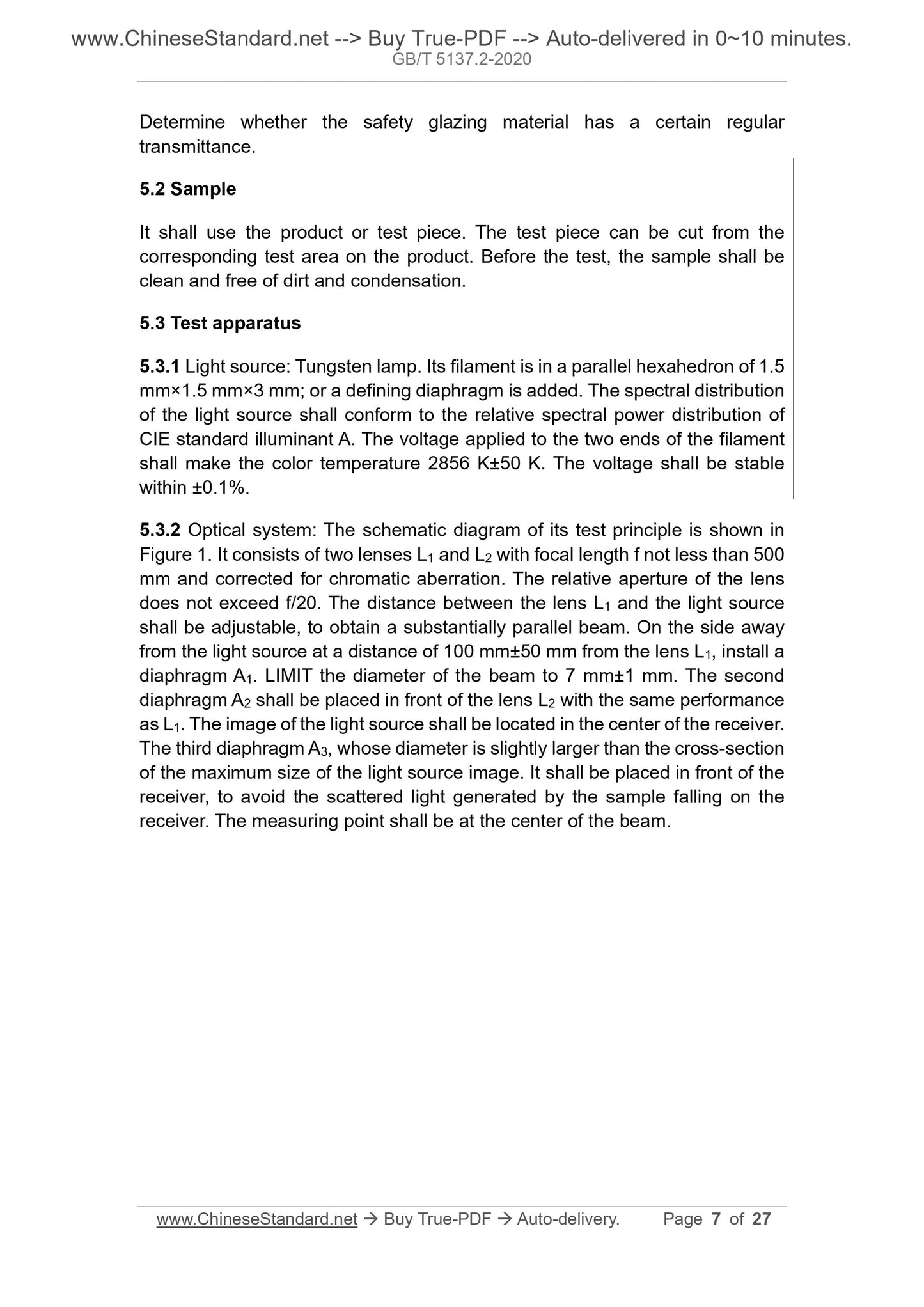
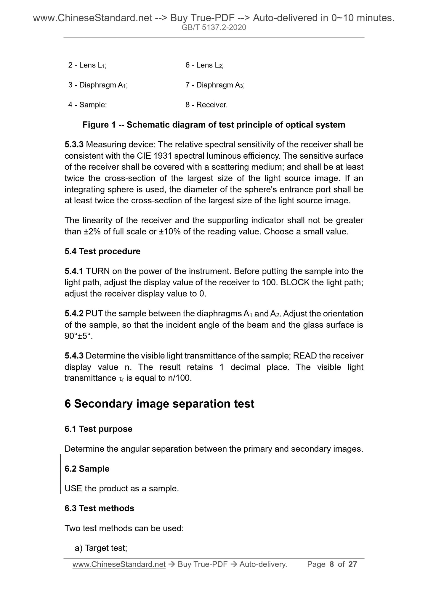
5.3.2 Optical system: The schematic diagram of its test principle is shown in
Figure 1. It consists of two lenses L1 and L2 with focal length f not less than 500
mm and corrected for chromatic aberration. The relative aperture of the lens
does not exceed f/20. The distance between the lens L1 and the light source
shall be adjustable, to obtain a substantially parallel beam. On the side away
from the light source at a distance of 100 mm±50 mm from the lens L1, install a
diaphragm A1. LIMIT the diameter of the beam to 7 mm±1 mm. The second
diaphragm A2 shall be placed in front of the lens L2 with the same performance
as L1. The image of the light source shall be located in the center of the receiver.
The third diaphragm A3, whose diameter is slightly larger than the cross-section
of the maximum size of the light source image. It shall be placed in front of the
receiver, to avoid the scattered light generated by the sample falling on the
receiver. The measuring point shall be at the center of the beam.
2 - Lens L1; 6 - Lens L2;
3 - Diaphragm A1; 7 - Diaphragm A3;
4 - Sample; 8 - Receiver.
Figure 1 -- Schematic diagram of test principle of optical system
5.3.3 Measuring device: The relative spectral sensitivity of the receiver shall be
consistent with the CIE 1931 spectral luminous efficiency. The sensitive surface
of the receiver shall be covered with a scattering medium; and shall be at least
twice the cross-section of the largest size of the light source image. If an
integrating sphere is used, the diameter of the sphere's entrance port shall be
at least twice the cross-section of the largest size of the light source image.
The linearity of the receiver and the supporting indicator shall not be greater
than ±2% of full scale or ±10% of the reading value. Choose a small value.
5.4 Test procedure
5.4.1 TURN on the power of the instrument. Before putting the sample into the
light path, adjust the display value of the receiver to 100. BLOCK the light path;
adjust the receiver display value to 0.
5.4.2 PUT the sample between the diaphragms A1 and A2. Adjust the orientation
of the sample, so that the incident angle of the beam and the glass surface is
90°±5°.
5.4.3 Determine the visible light transmittance of the sample; READ the receiver
display value n. The result retains 1 decimal place. The visible light
transmittance τr is equal to n/100.
6 Secondary image separation test
6.1 Test purpose
Determine the angular separation between the primary and secondary images.
6.2 Sample
USE the product as a sample.
6.3 Test methods
Two test methods can be used:
a) Target test;
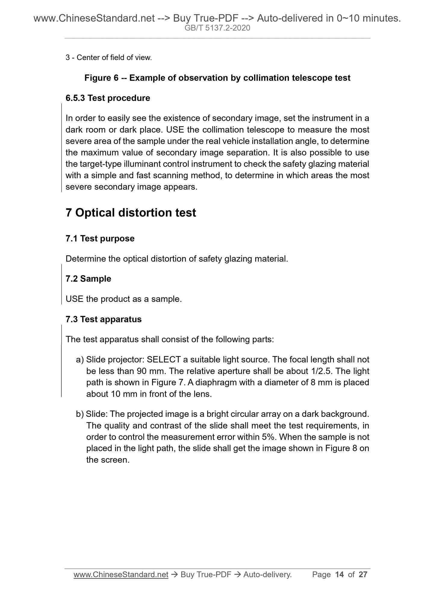
3 - Center of field of view.
Figure 6 -- Example of observation by collimation telescope test
6.5.3 Test procedure
In order to easily see the existence of secondary image, set the instrument in a
dark room or dark place. USE the collimation telescope to measure the most
severe area of the sample under the real vehicle installation angle, to determine
the maximum value of secondary image separation. It is also possible to use
the target-type illuminant control instrument to check the safety glazing material
with a simple and fast scanning method, to determine in which areas the most
severe secondary image appears.
7 Optical distortion test
7.1 Test purpose
Determine the optical distortion of safety glazing material.
7.2 Sample
USE the product as a sample.
7.3 Test apparatus
The test apparatus shall consist of the following parts:
a) Slide projector: SELECT a suitable light source. The focal length shall not
be less than 90 mm. The relative aperture shall be about 1/2.5. The light
path is shown in Figure 7. A diaphragm with a diameter of 8 mm is placed
about 10 mm in front of the lens.
b) Slide: The projected image is a bright circular array on a dark background.
The quality and contrast of the slide shall meet the test requirements, in
order to control the measurement error within 5%. When the sample is not
placed in the light path, the slide shall get the image shown in Figure 8 on
the screen.
Where:
Δα - Optical distortion, in minutes of arc (');
Δd - Maximum deformation, in millimeters (mm);
R2 - The distance from the sample to the screen, in meters (m).
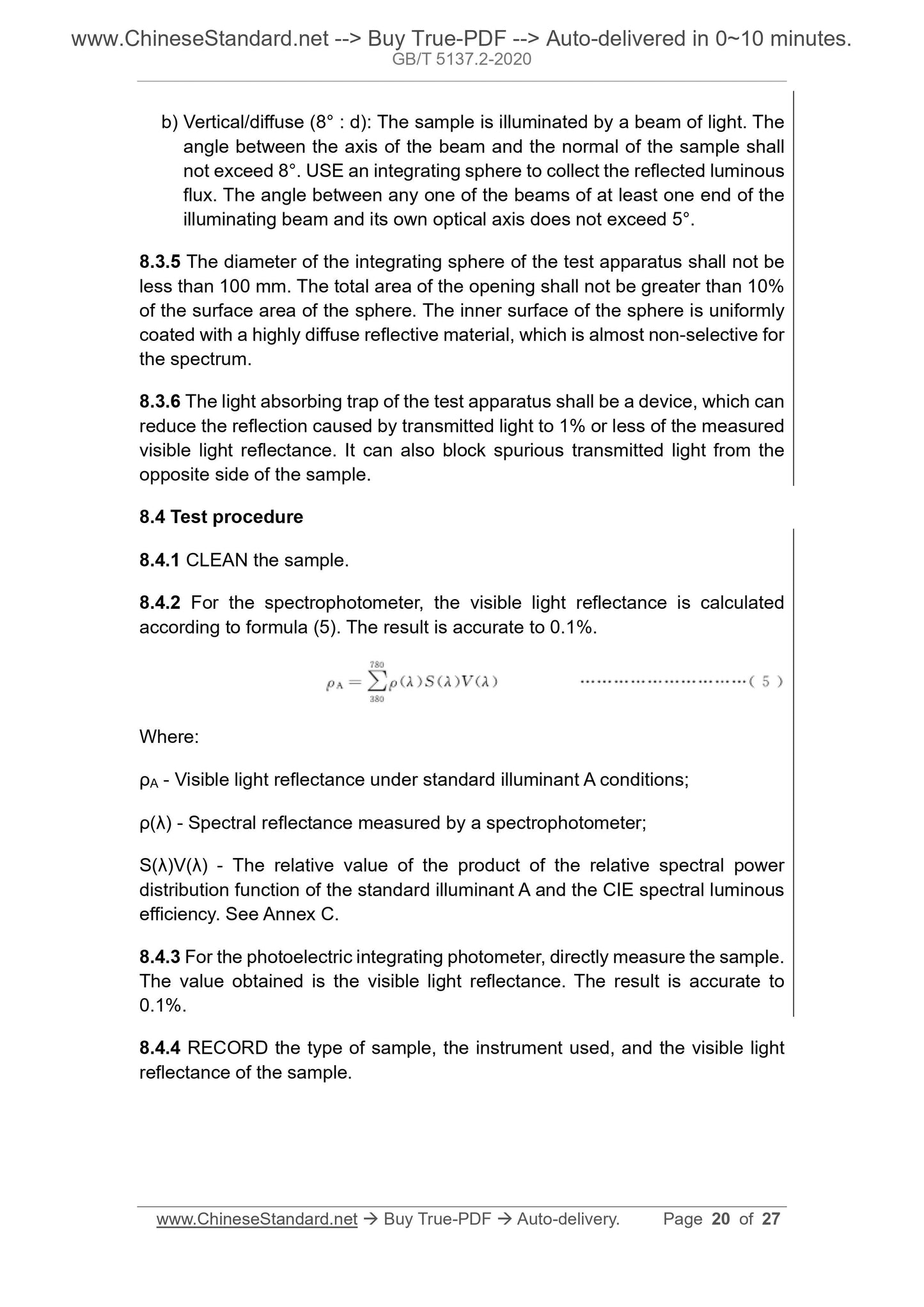
8 Visible light reflectance test
8.1 Test purpose
Determine the visible light reflectance of safety glazing material under standard
illuminant A condit...
Get QUOTATION in 1-minute: Click GB/T 5137.2-2020
Historical versions: GB/T 5137.2-2020
Preview True-PDF (Reload/Scroll if blank)
GB/T 5137.2-2020: Test methods of safety glazing materials used on road vehicles -- Part 2: Optical properties tests
GB/T 5137.2-2020
NATIONAL STANDARD OF THE
PEOPLE’S REPUBLIC OF CHINA
ICS 43.040.60
T 34
Replacing GB/T 5137.2-2002
Test methods of safety glazing materials used on road
vehicles - Part 2: Optical properties tests
(ISO 3538:1997, Road vehicles - Safety glazing materials -
Test methods for optical properties, MOD)
ISSUED ON: MARCH 31, 2020
IMPLEMENTED ON: FEBRUARY 01, 2021
Issued by: State Administration for Market Regulation;
Standardization Administration of the PRC.
Table of Contents
Foreword ... 3
1 Scope ... 6
2 Normative references ... 6
3 Terms and definitions ... 6
4 Test conditions ... 6
5 Visible light transmittance test ... 6
6 Secondary image separation test ... 8
7 Optical distortion test ... 14
8 Visible light reflectance test ... 19
Annex A (Informative) Structural changes of this Part compared with ISO
3538:1997 ... 21
Annex B (Informative) Technical differences between this Part and ISO
3538:1997 and their causes ... 24
Annex C (Informative) S(λ)V(λ) values ... 27
Test methods of safety glazing materials used on road
vehicles - Part 2: Optical properties tests
1 Scope
This Part of GB/T 5137 specifies the methods for visible light transmittance test,
secondary image separation test, optical distortion test, and visible light
reflectance test of safety glazing materials used on road vehicles.
This Part applies to the tests of safety glazing materials used on road vehicles.
2 Normative references
The following documents are indispensable for the application of this document.
For the dated references, only the editions with the dates indicated are
applicable to this document. For the undated references, the latest edition
(including all the amendments) are applicable to this document.
QC/T 1119 Road vehicles - Glazing materials - Terminology (QC/T 1119-
2019, ISO 3536:2016, MOD)
3 Terms and definitions
For the purposes of this document, the terms and definitions given in QC/T 1119
apply.
4 Test conditions
Unless otherwise specified, the tests shall be carried out under the following
ambient conditions:
a) Ambient temperature: 20 °C±5 °C;
b) Atmospheric pressure: 8.60×10⁴ Pa~1.06×10⁵ Pa;
c) Relative humidity: 40%~80%.
5 Visible light transmittance test
5.1 Test purpose
Determine whether the safety glazing material has a certain regular
transmittance.
5.2 Sample
It shall use the product or test piece. The test piece can be cut from the
corresponding test area on the product. Before the test, the sample shall be
clean and free of dirt and condensation.
5.3 Test apparatus
5.3.1 Light source: Tungsten lamp. Its filament is in a parallel hexahedron of 1.5
mm×1.5 mm×3 mm; or a defining diaphragm is added. The spectral distribution
of the light source shall conform to the relative spectral power distribution of
CIE standard illuminant A. The voltage applied to the two ends of the filament
shall make the color temperature 2856 K±50 K. The voltage shall be stable
within ±0.1%.
5.3.2 Optical system: The schematic diagram of its test principle is shown in
Figure 1. It consists of two lenses L1 and L2 with focal length f not less than 500
mm and corrected for chromatic aberration. The relative aperture of the lens
does not exceed f/20. The distance between the lens L1 and the light source
shall be adjustable, to obtain a substantially parallel beam. On the side away
from the light source at a distance of 100 mm±50 mm from the lens L1, install a
diaphragm A1. LIMIT the diameter of the beam to 7 mm±1 mm. The second
diaphragm A2 shall be placed in front of the lens L2 with the same performance
as L1. The image of the light source shall be located in the center of the receiver.
The third diaphragm A3, whose diameter is slightly larger than the cross-section
of the maximum size of the light source image. It shall be placed in front of the
receiver, to avoid the scattered light generated by the sample falling on the
receiver. The measuring point shall be at the center of the beam.
2 - Lens L1; 6 - Lens L2;
3 - Diaphragm A1; 7 - Diaphragm A3;
4 - Sample; 8 - Receiver.
Figure 1 -- Schematic diagram of test principle of optical system
5.3.3 Measuring device: The relative spectral sensitivity of the receiver shall be
consistent with the CIE 1931 spectral luminous efficiency. The sensitive surface
of the receiver shall be covered with a scattering medium; and shall be at least
twice the cross-section of the largest size of the light source image. If an
integrating sphere is used, the diameter of the sphere's entrance port shall be
at least twice the cross-section of the largest size of the light source image.
The linearity of the receiver and the supporting indicator shall not be greater
than ±2% of full scale or ±10% of the reading value. Choose a small value.
5.4 Test procedure
5.4.1 TURN on the power of the instrument. Before putting the sample into the
light path, adjust the display value of the receiver to 100. BLOCK the light path;
adjust the receiver display value to 0.
5.4.2 PUT the sample between the diaphragms A1 and A2. Adjust the orientation
of the sample, so that the incident angle of the beam and the glass surface is
90°±5°.
5.4.3 Determine the visible light transmittance of the sample; READ the receiver
display value n. The result retains 1 decimal place. The visible light
transmittance τr is equal to n/100.
6 Secondary image separation test
6.1 Test purpose
Determine the angular separation between the primary and secondary images.
6.2 Sample
USE the product as a sample.
6.3 Test methods
Two test methods can be used:
a) Target test;
3 - Center of field of view.
Figure 6 -- Example of observation by collimation telescope test
6.5.3 Test procedure
In order to easily see the existence of secondary image, set the instrument in a
dark room or dark place. USE the collimation telescope to measure the most
severe area of the sample under the real vehicle installation angle, to determine
the maximum value of secondary image separation. It is also possible to use
the target-type illuminant control instrument to check the safety glazing material
with a simple and fast scanning method, to determine in which areas the most
severe secondary image appears.
7 Optical distortion test
7.1 Test purpose
Determine the optical distortion of safety glazing material.
7.2 Sample
USE the product as a sample.
7.3 Test apparatus
The test apparatus shall consist of the following parts:
a) Slide projector: SELECT a suitable light source. The focal length shall not
be less than 90 mm. The relative aperture shall be about 1/2.5. The light
path is shown in Figure 7. A diaphragm with a diameter of 8 mm is placed
about 10 mm in front of the lens.
b) Slide: The projected image is a bright circular array on a dark background.
The quality and contrast of the slide shall meet the test requirements, in
order to control the measurement error within 5%. When the sample is not
placed in the light path, the slide shall get the image shown in Figure 8 on
the screen.
Where:
Δα - Optical distortion, in minutes of arc (');
Δd - Maximum deformation, in millimeters (mm);
R2 - The distance from the sample to the screen, in meters (m).
8 Visible light reflectance test
8.1 Test purpose
Determine the visible light reflectance of safety glazing material under standard
illuminant A condit...
Share