1
/
de
12
PayPal, credit cards. Download editable-PDF and invoice in 1 second!
GB/Z 27764-2011 English PDF (GBZ27764-2011)
GB/Z 27764-2011 English PDF (GBZ27764-2011)
Prix habituel
$460.00 USD
Prix habituel
Prix promotionnel
$460.00 USD
Prix unitaire
/
par
Frais d'expédition calculés à l'étape de paiement.
Impossible de charger la disponibilité du service de retrait
Delivery: 3 seconds. Download true-PDF + Invoice.
Get QUOTATION in 1-minute: Click GB/Z 27764-2011
Historical versions: GB/Z 27764-2011
Preview True-PDF (Reload/Scroll if blank)
GB/Z 27764-2011: Acoustics -- Determination of sound transmission loss in impedance tubes -- Transfer matrix method
GB/Z 27764-2011
GB
GUIDANCE TECHNICAL DOCUMENT FOR
STANDARDIZATION OF THE PEOPLE’S REPUBLIC OF CHINA
ICS 17.140.01
A 59
Acoustics - Determination of sound transmission loss in
impedance tubes - Transfer matrix method
ISSUED ON: DECEMBER 30, 2011
IMPLEMENTED ON: MAY 01, 2012
Issued by: State Administration for Market Regulation;
Standardization Administration of PRC.
Table of Contents
Foreword ... 3
1 Scope ... 4
2 Normative references ... 4
3 Terms and definitions ... 4
4 Principles ... 7
5 Test equipment ... 8
6 Preliminary test ... 15
7 Installation of test pieces ... 16
8 Test steps ... 17
9 Measurement uncertainty ... 21
10 Test report ... 21
Appendix A (Normative) Preliminary test ... 23
Appendix B (Normative) Measurement theory ... 27
Appendix C (Informative) Measurement instructions for flexible sheet materials ... 30
Appendix D (Informative) Sources of error and calculation of measurement uncertainty
... 32
References ... 41
Acoustics - Determination of sound transmission loss in
impedance tubes - Transfer matrix method
1 Scope
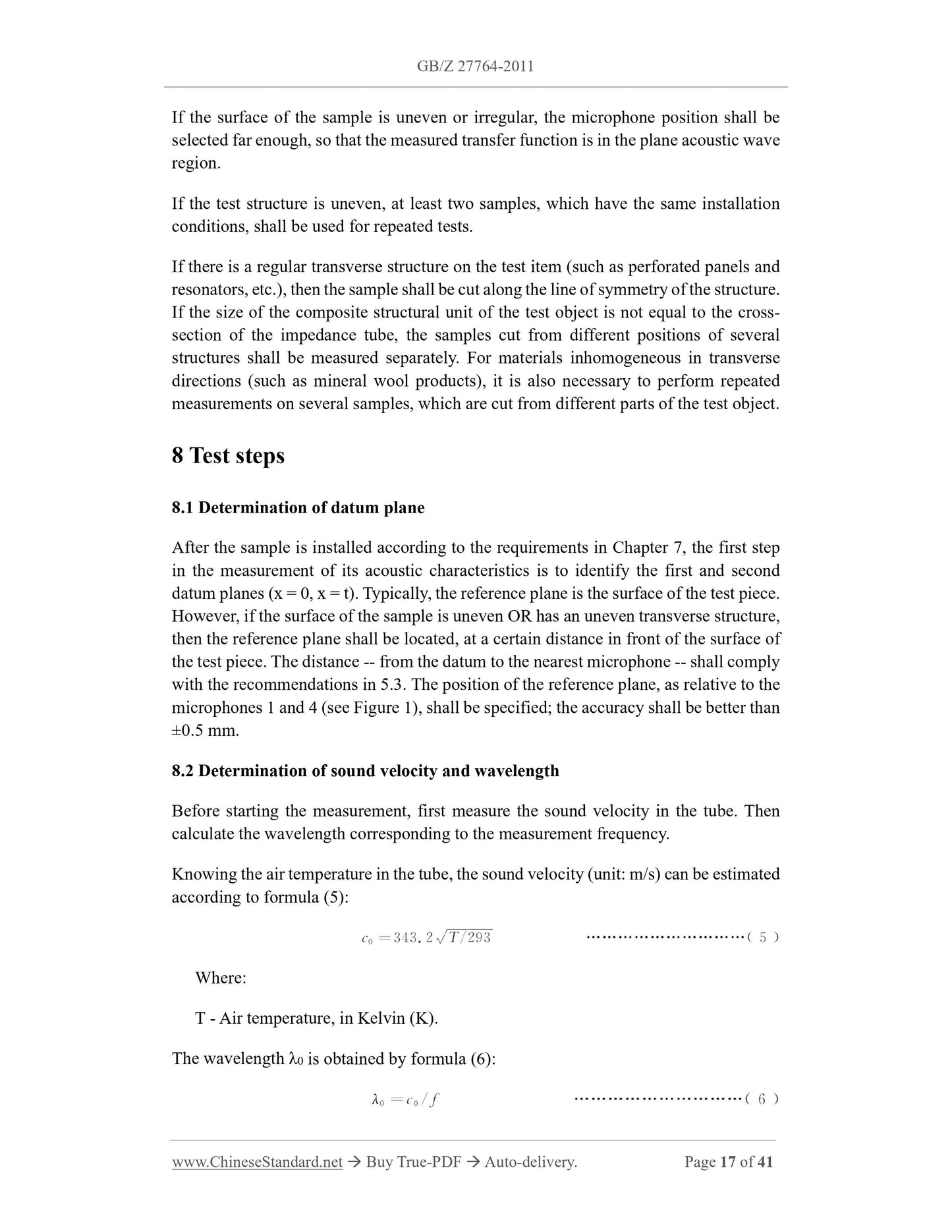
This guiding technical document stipulates the measurement of normal incidence sound
insulation (or normal incidence sound transmission loss) of acoustic materials or
acoustic structures, in impedance tubes, by using the transfer matrix method.
This guiding technical document is applicable to the measurement of the normal
incidence sound insulation of locally reactive acoustic materials, such as sponges,
cotton felts, soft thin plates, whose test frequency is in the quality control area (that is,
there is no sound propagation parallel to the material inside the material). It is applicable
to the comparison of sound insulation performance of acoustic materials, in the
development stage. Since the sound transmission loss of a material is closely related to
its physical properties (such as elastic modulus, density, structure factor, etc.), the
measurement methods specified in this guiding technical document can be applied to
relevant basic research and product development.
This guiding technical document is not applicable to the identification test of the sound
insulation performance of the product.
This guiding technical document uses an impedance tube, one or more microphones,
and a digital acquisition and analysis system.
2 Normative references
The following documents are essential to the application of this document. For the dated
documents, only the versions with the dates indicated are applicable to this document;
for the undated documents, only the latest version (including all the amendments) is
applicable to this standard.
GB/T 3947-1996 Acoustical terminology
GB/T 18696.2-2002 Acoustics - Determination of sound absorption coefficient and
impedance in impedance tubes - Part 2: Transfer function method
3 Terms and definitions
The following terms and definitions apply to this document.
3.1
Normal incidence [sound] pressure transmission coefficient
τp
The ratio -- of the sound pressure transmitted through a material or structure TO the
incident sound pressure, when the sound wave is incident on the normal direction.
Note: Rewrite GB/T 3947-1996, Terms and Definitions 12.37.
3.2
Normal incidence [sound] transmission loss
TL
The difference -- between the incident sound power level on one side of the material
and the transmitted sound power level on the other side -- when the sound wave is
incident on the normal direction. The sound transmission loss is equal to the
reciprocal of the square of the sound pressure transmission coefficient, taking the
logarithm to the base 10, in the unit of Bell [B]. However, it is usually measured in
decibels (dB).
Note: Rewrite GB/T 3947-1996, Terms and Definitions 12.26.
3.3
The first reference plane
The cross-section of the impedance tube, which is used to measure the sound
pressure transmission coefficient. If the surface of the test piece is flat, usually take
the front surface of the sample as the first reference plane.
Note: Rewrite GB/T 18696.2-2002, Terms and Definitions 3.3.
3.4
The second reference plane
The cross-section of the impedance tube, which is used to measure the sound
pressure transmission coefficient. If the surface of the test piece is flat and the
thickness of the sample is t, the second reference plane is usually taken at x = t.
Note: Rewrite GB/T 18696.2-2002, Terms and Definitions 3.3.
3.5
Wave number in the air
sequence noise or chirp. Measure the sound pressure, at two positions close to the
sample in the front tube, to obtain the sound pressure transfer function of the two
microphone signals. Similarly, measure the sound pressure, at two positions close to the
sample in the back tube, to obtain the sound pressure transfer function of the two
microphone signals. Calculate the normal incident transmission coefficient of the test
piece (see Appendix B), sound transmission loss, other related acoustic quantities, by
the transfer matrix method.
These quantities are all functions of frequency. Frequency resolution depends on the
sampling frequency and the measurement record length of the digital acquisition and
analysis system. The effective frequency range is related to the lateral dimension or
diameter of the impedance tube, as well as the spacing between the two microphones.
With different sizes or combinations of diameter and spacing, a wide range of
measuring frequencies can be obtained.
Measurements can be made in one of two ways:
a) Four-microphone method (measured by four microphones at a fixed position);
b) Single-microphone method (measured by one microphone at four positions in
sequence).
5 Test equipment
5.1 Structure of impedance tube
The impedance tube is divided into front tube, back tube, test piece holding tube. One
end of the front tube is connected to the sound source, the other end is connected to the
test piece holding tube. One end of the rear tube is connected to the test piece holding
tube, the other end is a closed end with certain sound absorption performance. There
are four microphone mounting holes, two for the front tube and two for the rear tube,
arranged along the tube wall.
The impedance tube shall be straight; its cross-sectional area shall be uniform (the
deviation of diameter or cross-sectional size is within ±0.2%); the wall of the tube shall
be smooth, rigid, dense enough, so that it will not be excited by the acoustic signal.
There is no resonance in the working frequency band of the impedance tube. For round
metal tubes, it is recommended that the wall thickness be taken as about 5% of the tube
diameter. For rectangular tubes, the four corners must have sufficient rigidity, to prevent
deformation of the side plates. It is recommended that the plate thickness be taken as
10% of the cross-sectional size of the impedance tube. The tube wall, which is made of
cement, can be painted with a well-mixed adhesive, to ensure airtightness. The same
measures shall be taken for tube walls, which are made of wood. Cement tube walls
and wooden tube walls shall also be covered with iron or lead, to increase strength and
damping.
if the requirements of formula (4) are met, the distance between the microphones shall
be greater than 5% of the corresponding wavelength of the test low frequency.
Increasing the distance between the microphones can improve the measurement
accuracy.
If it wants to expand the t...
Get QUOTATION in 1-minute: Click GB/Z 27764-2011
Historical versions: GB/Z 27764-2011
Preview True-PDF (Reload/Scroll if blank)
GB/Z 27764-2011: Acoustics -- Determination of sound transmission loss in impedance tubes -- Transfer matrix method
GB/Z 27764-2011
GB
GUIDANCE TECHNICAL DOCUMENT FOR
STANDARDIZATION OF THE PEOPLE’S REPUBLIC OF CHINA
ICS 17.140.01
A 59
Acoustics - Determination of sound transmission loss in
impedance tubes - Transfer matrix method
ISSUED ON: DECEMBER 30, 2011
IMPLEMENTED ON: MAY 01, 2012
Issued by: State Administration for Market Regulation;
Standardization Administration of PRC.
Table of Contents
Foreword ... 3
1 Scope ... 4
2 Normative references ... 4
3 Terms and definitions ... 4
4 Principles ... 7
5 Test equipment ... 8
6 Preliminary test ... 15
7 Installation of test pieces ... 16
8 Test steps ... 17
9 Measurement uncertainty ... 21
10 Test report ... 21
Appendix A (Normative) Preliminary test ... 23
Appendix B (Normative) Measurement theory ... 27
Appendix C (Informative) Measurement instructions for flexible sheet materials ... 30
Appendix D (Informative) Sources of error and calculation of measurement uncertainty
... 32
References ... 41
Acoustics - Determination of sound transmission loss in
impedance tubes - Transfer matrix method
1 Scope
This guiding technical document stipulates the measurement of normal incidence sound
insulation (or normal incidence sound transmission loss) of acoustic materials or
acoustic structures, in impedance tubes, by using the transfer matrix method.
This guiding technical document is applicable to the measurement of the normal
incidence sound insulation of locally reactive acoustic materials, such as sponges,
cotton felts, soft thin plates, whose test frequency is in the quality control area (that is,
there is no sound propagation parallel to the material inside the material). It is applicable
to the comparison of sound insulation performance of acoustic materials, in the
development stage. Since the sound transmission loss of a material is closely related to
its physical properties (such as elastic modulus, density, structure factor, etc.), the
measurement methods specified in this guiding technical document can be applied to
relevant basic research and product development.
This guiding technical document is not applicable to the identification test of the sound
insulation performance of the product.
This guiding technical document uses an impedance tube, one or more microphones,
and a digital acquisition and analysis system.
2 Normative references
The following documents are essential to the application of this document. For the dated
documents, only the versions with the dates indicated are applicable to this document;
for the undated documents, only the latest version (including all the amendments) is
applicable to this standard.
GB/T 3947-1996 Acoustical terminology
GB/T 18696.2-2002 Acoustics - Determination of sound absorption coefficient and
impedance in impedance tubes - Part 2: Transfer function method
3 Terms and definitions
The following terms and definitions apply to this document.
3.1
Normal incidence [sound] pressure transmission coefficient
τp
The ratio -- of the sound pressure transmitted through a material or structure TO the
incident sound pressure, when the sound wave is incident on the normal direction.
Note: Rewrite GB/T 3947-1996, Terms and Definitions 12.37.
3.2
Normal incidence [sound] transmission loss
TL
The difference -- between the incident sound power level on one side of the material
and the transmitted sound power level on the other side -- when the sound wave is
incident on the normal direction. The sound transmission loss is equal to the
reciprocal of the square of the sound pressure transmission coefficient, taking the
logarithm to the base 10, in the unit of Bell [B]. However, it is usually measured in
decibels (dB).
Note: Rewrite GB/T 3947-1996, Terms and Definitions 12.26.
3.3
The first reference plane
The cross-section of the impedance tube, which is used to measure the sound
pressure transmission coefficient. If the surface of the test piece is flat, usually take
the front surface of the sample as the first reference plane.
Note: Rewrite GB/T 18696.2-2002, Terms and Definitions 3.3.
3.4
The second reference plane
The cross-section of the impedance tube, which is used to measure the sound
pressure transmission coefficient. If the surface of the test piece is flat and the
thickness of the sample is t, the second reference plane is usually taken at x = t.
Note: Rewrite GB/T 18696.2-2002, Terms and Definitions 3.3.
3.5
Wave number in the air
sequence noise or chirp. Measure the sound pressure, at two positions close to the
sample in the front tube, to obtain the sound pressure transfer function of the two
microphone signals. Similarly, measure the sound pressure, at two positions close to the
sample in the back tube, to obtain the sound pressure transfer function of the two
microphone signals. Calculate the normal incident transmission coefficient of the test
piece (see Appendix B), sound transmission loss, other related acoustic quantities, by
the transfer matrix method.
These quantities are all functions of frequency. Frequency resolution depends on the
sampling frequency and the measurement record length of the digital acquisition and
analysis system. The effective frequency range is related to the lateral dimension or
diameter of the impedance tube, as well as the spacing between the two microphones.
With different sizes or combinations of diameter and spacing, a wide range of
measuring frequencies can be obtained.
Measurements can be made in one of two ways:
a) Four-microphone method (measured by four microphones at a fixed position);
b) Single-microphone method (measured by one microphone at four positions in
sequence).
5 Test equipment
5.1 Structure of impedance tube
The impedance tube is divided into front tube, back tube, test piece holding tube. One
end of the front tube is connected to the sound source, the other end is connected to the
test piece holding tube. One end of the rear tube is connected to the test piece holding
tube, the other end is a closed end with certain sound absorption performance. There
are four microphone mounting holes, two for the front tube and two for the rear tube,
arranged along the tube wall.
The impedance tube shall be straight; its cross-sectional area shall be uniform (the
deviation of diameter or cross-sectional size is within ±0.2%); the wall of the tube shall
be smooth, rigid, dense enough, so that it will not be excited by the acoustic signal.
There is no resonance in the working frequency band of the impedance tube. For round
metal tubes, it is recommended that the wall thickness be taken as about 5% of the tube
diameter. For rectangular tubes, the four corners must have sufficient rigidity, to prevent
deformation of the side plates. It is recommended that the plate thickness be taken as
10% of the cross-sectional size of the impedance tube. The tube wall, which is made of
cement, can be painted with a well-mixed adhesive, to ensure airtightness. The same
measures shall be taken for tube walls, which are made of wood. Cement tube walls
and wooden tube walls shall also be covered with iron or lead, to increase strength and
damping.
if the requirements of formula (4) are met, the distance between the microphones shall
be greater than 5% of the corresponding wavelength of the test low frequency.
Increasing the distance between the microphones can improve the measurement
accuracy.
If it wants to expand the t...
Share